steering oil GEELY MK 2008 Owner's Manual
[x] Cancel search | Manufacturer: GEELY, Model Year: 2008, Model line: MK, Model: GEELY MK 2008Pages: 416, PDF Size: 25.19 MB
Page 105 of 416

Propeller Shaft/DriveshaftFront Driveshaft4-28 Hint:
Please refer to the following table for dimension (A).LH mm
528.3±5.0
527.0±5.0RH mm
859.3±5.0
860.0±5.0 M/T manual transmission
A/T automatic transmission38. Install left constant velocity drive shaft assembly
(1) M/T
Coat the spline of the tripod joint assembly with gear oil.
(2) A/T
Coat the spline of the tripod joint assembly with ATF
(Automatic Transmission Fluid).
(3) Align the spline, use a brass bar and hammer to install the left
drive shaft assembly.
Notice:
Face the retainer open end downward.
Be careful not to damage the boot and oil seal.
Hint:
You can find out whether the tripod joint shaft contact the pinion shaft by rotating the shaft assembly, listening
to the sound and feeling.
39. Install right constant velocity drive shaft assembly
Hint:
The installation of the right side is the same as that of the left side.
Notice:
Install the retainer with its open end facing downward.
Be careful not to damage the boot and oil seal.
40. Install left steering knuckle assembly
Install the left constant velocity drive shaft assembly on the left steering knuckle assembly.
Notice:
Be careful not to damage the outboard joint boot.
With ABS:
Be careful not to damage the vehicle speed sensor rotor.
41. Install left steering gear with tie rod assembly
(1) Install the steering gear with tie rod assembly on the steering knuckle assembly with nuts.
Torque: 33N.m
(2) Install the new cotter pins.
Notice:
If the pin holes are not aligned, further tighten the nut by 60°.
42. Install left lower swing arm assembly
(1) Install the left lower swing arm assembly on the steering knuckle assembly with nuts.
Torque: 98N.m -
Page 106 of 416

Propeller Shaft/DriveshaftFront Driveshaft4-29 (2) Install the new cotter pins.
Notice:
If the pin holes are not aligned, further tighten the nut by 60°.
43. Install front stabilizer bar
(1) As shown in the illustration, install the stabilizer bar with two
No.1 collars and two gaskets and nuts.
Notice:
Make sure the gaskets and collars are correctly installed.
(2) Tighten the nut with a 10mm wrench.
Torque: 18N.m
44. Install left front vehicle speed sensor (with ABS)
(1) Install the left front vehicle speed sensor and brake hose on the
front shock absorber with bolts and clps.
Torque: 29N.m
(2) Install the vehicle speed sensor on the steering knuckle with
bolts.
Torque: 8.0N.m
Notice:
Be careful not to damage the wheel speed sensor.
Keep the vehicle speed sensor clean.
When installing the sensor,do not twist the sensor wire harness.
45. Install left steering knuckle wheel hub nut
(1) Install new left steering knuckle hub nuts
Torque: 216N.m
(2) Using a chisel and hammer, stake the hub locking nut.
46. Install engine bottom left shield
47. Install engine bottom right shield
48. Install engine bottom shield assembly
49. Install front wheel
Torque: 103 N.m
50. Add oil into manual transmission
51. Check and adjust the manual transmission fluid
52. Refill automatic transmission fluid
53. Check and adjust the automatic transmission fluid
54. Check and adjust front wheel alignment
55. Check ABS vehicle speed signal (with ABS) -
Page 110 of 416

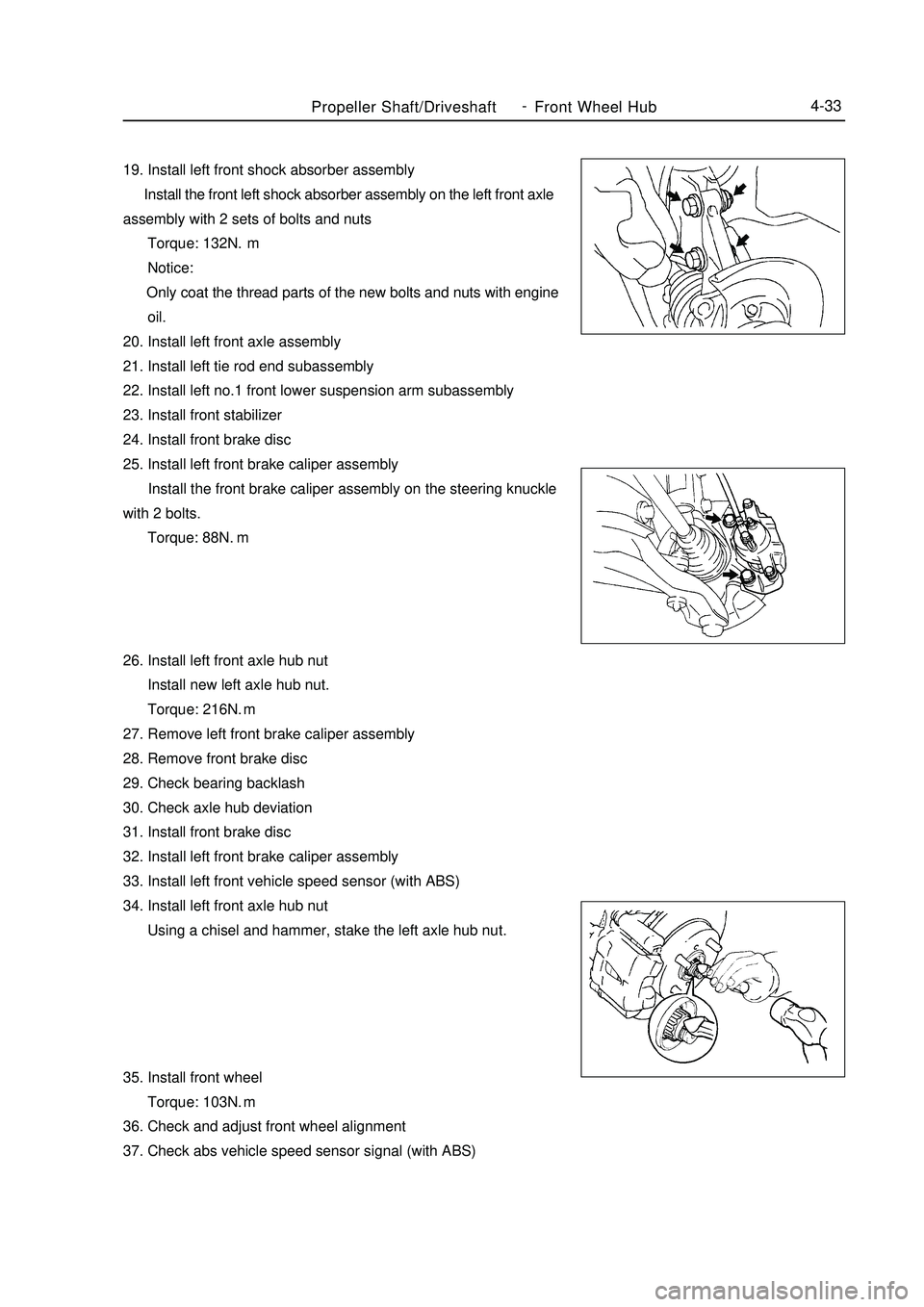
Propeller Shaft/DriveshaftFront Wheel Hub4-3319. Install left front shock absorber assembly
Install the front left shock absorber assembly on the left front axle
assembly with 2 sets of bolts and nuts
Torque: 132N.m
Notice:
Only coat the thread parts of the new bolts and nuts with engine
oil.
20. Install left front axle assembly
21. Install left tie rod end subassembly
22. Install left no.1 front lower suspension arm subassembly
23. Install front stabilizer
24. Install front brake disc
25. Install left front brake caliper assembly
Install the front brake caliper assembly on the steering knuckle
with 2 bolts.
Torque: 88N.
m
26. Install left front axle hub nut
Install new left axle hub nut.
Torque: 216N.m
27. Remove left front brake caliper assembly
28. Remove front brake disc
29. Check bearing backlash
30. Check axle hub deviation
31. Install front brake disc
32. Install left front brake caliper assembly
33. Install left front vehicle speed sensor (with ABS)
34. Install left front axle hub nut
Using a chisel and hammer, stake the left axle hub nut.
35. Install front wheel
Torque: 103N.m
36. Check and adjust front wheel alignment
37. Check abs vehicle speed sensor signal (with ABS) -
Page 115 of 416

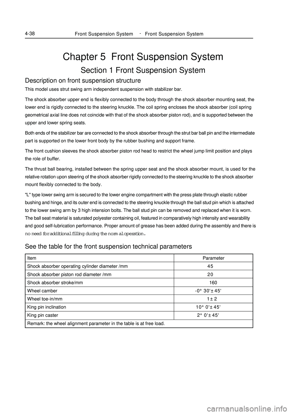
Chapter 5 Front Suspension SystemSection 1 Front Suspension SystemDescription on front suspension structureThis model uses strut swing arm independent suspension with stabilizer bar.
The shock absorber upper end is flexibly connected to the body through the shock absorber mounting seat, the
lower end is rigidly connected to the steering knuckle. The coil spring encloses the shock absorber (coil spring
geometrical axial line does not coincide with that of the shock absorber piston rod), and is supported between the
upper and lower spring seats.
Both ends of the stabilizer bar are connected to the shock absorber through the strut bar ball pin and the intermediate
part is supported on the lower front body by the rubber bushing and support frame.
The front cushion sleeves the shock absorber piston rod head to restrict the wheel jump limit position and plays
the role of buffer.
The thrust ball bearing, installed between the spring upper seat and the shock absorber mount, is used for the
relative rotation upon steering of the shock absorber rigidly connected to the steering knuckle to the shock absorber
mount flexibly connected to the body.
"L" type lower swing arm is secured to the lower engine compartment with the press plate through elastic rubber
bushing and hinge, and its outer end is connected to the steering knuckle through the ball stud pin which is attached
to the lower swing arm by 3 high intension bolts. The ball stud pin can be removed and replaced when it is worn.
The ball seat material is saturated polyester containing oil, featured in comparatively high intensity and wearability
and good self-lubrication performance. Proper amount of grease has been added during the assembly and there is
no need for additional filling during the normal operation.See the table for the front suspension technical parametersFront Suspension SystemFront Suspension System4-38Item
Shock absorber operating cylinder diameter /mm
Shock absorber piston rod diameter /mm
Shock absorber stroke/mm
Wheel camber
Wheel toe-in/mm
King pin inclination
King pin caster
Remark: the wheel alignment parameter in the table is at free load.Parameter
45
20
160
-0°30'±45'
1±2
10°0'±45'
2°0'±45' -
Page 121 of 416

Camber angle
Left-right wheel deviation
Caster angle
Manual steering
Power steering
Left-right wheel deviation
Kingpin inclination
Manual steering
Power steering
Left-right wheel deviation-0°30' ± 45' (-0.5° ± 0.75°)
45'(0.75°) or smaller
1°46' ± 45' (1.76° ± 0.75°)
45' (0.75°) or smaller
9°54' ± 45' (9.90° ± 0.75°)
45' (0.75°) or lessFront Suspension SystemFront Wheel Alignment4-44Manual steering Power steering
Inside wheel 9-137.2°±2°
Outside wheel32°±2° 32°±2°5. Check the steering angle of wheel
Fully steer the wheel and measure the angle
The angle of wheel:
If the kingpin caster angle and the kingpin inclination be out of spec, check the damage and abrasion of
suspension parts after the correct adjustment of camber angle. If there is deviation with spec for right and left wheel angle, check the rack length of left and right ends.
6. Check the camber, caster and steering axle inclination angle
7. Adjust the camber angle
Notice:
Check the toe-in after adjust the camber angle
(1)Remove the front wheel
(2)Remove the two nuts under the shock absorber
If you need to reuse the bolts and nuts, apply the engine oil on
the nut thread
(3)Clear the mounting surface of the knuckle and shock absorber.Front
Inside
Outside
meter
locator-9-1
Page 151 of 416

Power Steering System-
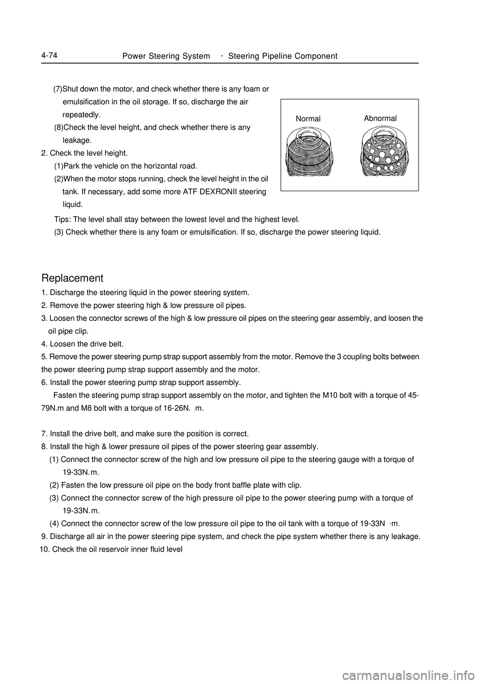
Steering Pipeline Component4-74 (7)Shut down the motor, and check whether there is any foam or
emulsification in the oil storage. If so, discharge the air
repeatedly.
(8)Check the level height, and check whether there is any
leakage.
2. Check the level height.
(1)Park the vehicle on the horizontal road.
(2)When the motor stops running, check the level height in the oil
tank. If necessary, add some more ATF DEXRONII steering
liquid.Replacement1. Discharge the steering liquid in the power steering system.
2. Remove the power steering high & low pressure oil pipes.
3. Loosen the connector screws of the high & low pressure oil pipes on the steering gear assembly, and loosen the
oil pipe clip.
4. Loosen the drive belt.
5. Remove the power steering pump strap support assembly from the motor. Remove the 3 coupling bolts between
the power steering pump strap support assembly and the motor.
6. Install the power steering pump strap support assembly.
Fasten the steering pump strap support assembly on the motor, and tighten the M10 bolt with a torque of 45-
79N.m and M8 bolt with a torque of 16-26N.m.
7. Install the drive belt, and make sure the position is correct.
8. Install the high & lower pressure oil pipes of the power steering gear assembly.
(1) Connect the connector screw of the high and low pressure oil pipe to the steering gauge with a torque of
19-33N.m.
(2) Fasten the low pressure oil pipe on the body front baffle plate with clip.
(3) Connect the connector screw of the high pressure oil pipe to the power steering pump with a torque of
19-33N.m.
(4) Connect the connector screw of the low pressure oil pipe to the oil tank with a torque of 19-33N.
m.
9. Discharge all air in the power steering pipe system, and check the pipe system whether there is any leakage.
10. Check the oil reservoir inner fluid level Tips: The level shall stay between the lowest level and the highest level.
(3) Check whether there is any foam or emulsification. If so, discharge the power steering liquid.NormalAbnormal
Page 153 of 416

Steering rack end sub-assembly
Steering rack end sub-assembly
Left ball extension shaft Left ball extension shaftComponent ViewPower Steering System-Power Steering Gear4-76Lock nut
Steering rack # 1 dust shield
Clip
Hoop
O-ring Steering hydraulic
oil pipe
O-ring
Hoop
Clip O-ring
Steering rack # 2 dust shield
Non-reusable parts
Power steering oil
Special toolLock nut
Specified torque
Page 413 of 416

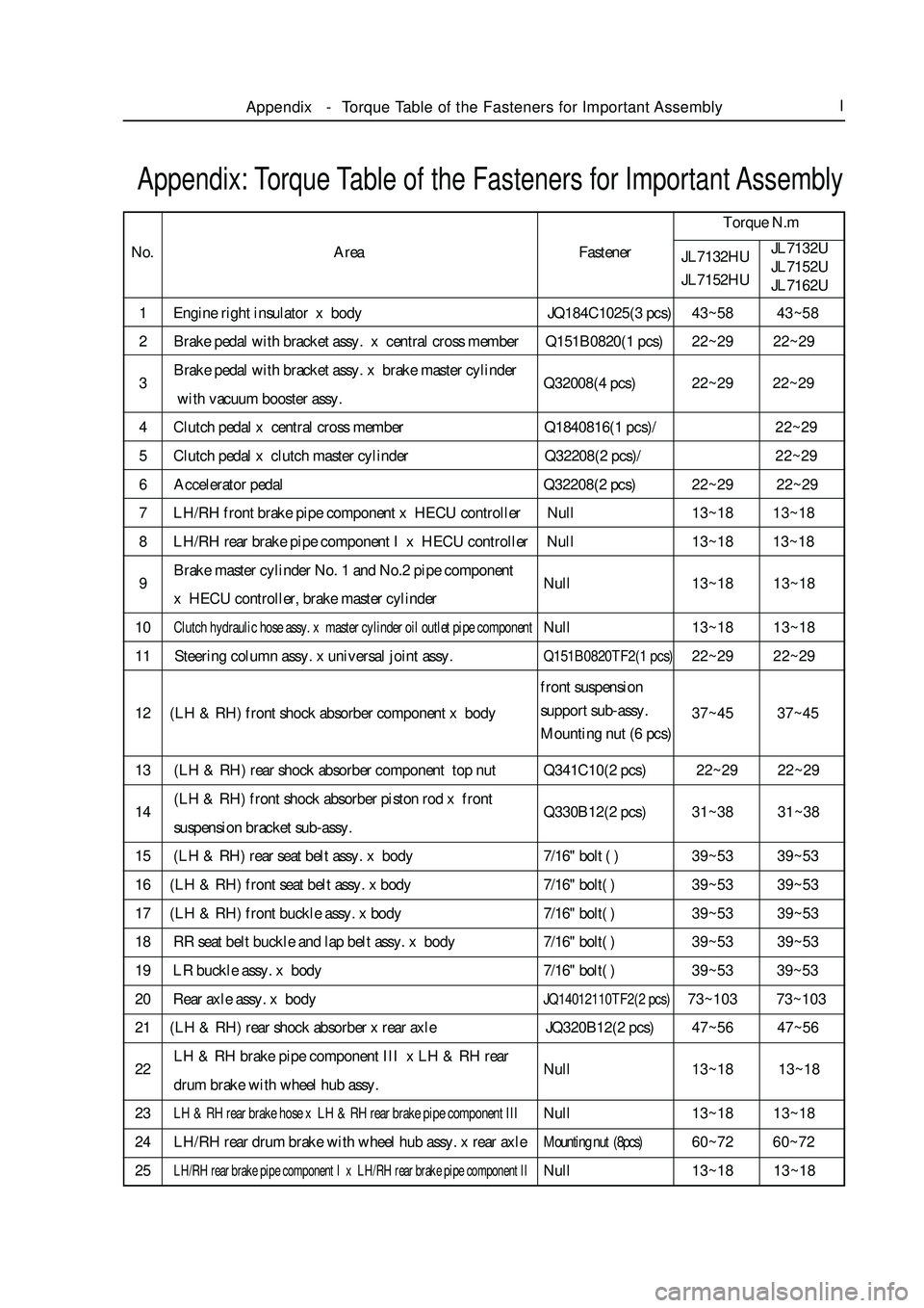
1 Engine right insulator x body JQ184C1025(3 pcs)43~58 43~58
2 Brake pedal with bracket assy. x central cross member Q151B0820(1 pcs)22~29 22~29
3Brake pedal with bracket assy. x brake master cylinder
Q32008(4 pcs)22~29 22~29
with vacuum booster assy.
4 Clutch pedal x central cross member Q1840816(1 pcs)/22~29
5 Clutch pedal x clutch master cylinder Q32208(2 pcs)/22~29
6 Accelerator pedal Q32208(2 pcs)22~29 22~29
7 LH/RH front brake pipe component x HECU controller Null13~18 13~18
8 LH/RH rear brake pipe component I x HECU controller Null13~18 13~18
9Brake master cylinder No. 1 and No.2 pipe component
Null13~18 13~18
x HECU controller, brake master cylinder
10Clutch hydraulic hose assy. x master cylinder oil outlet pipe componentNull13~18 13~18
11 Steering column assy. x universal joint assy.Q151B0820TF2(1 pcs)22~29 22~29
12 (LH & RH) front shock absorber component x body37~45 37~45
13 (LH & RH) rear shock absorber component top nut Q341C10(2 pcs) 22~29 22~29
14(LH & RH) front shock absorber piston rod x front
Q330B12(2 pcs)31~38 31~38
suspension bracket sub-assy.
15 (LH & RH) rear seat belt assy. x body7/16" bolt ( )39~53 39~53
16 (LH & RH) front seat belt assy. x body7/16" bolt( )39~53 39~53
17 (LH & RH) front buckle assy. x body7/16" bolt( )39~53 39~53
18 RR seat belt buckle and lap belt assy. x body7/16" bolt( )39~53 39~53
19 LR buckle assy. x body7/16" bolt( )39~53 39~53
20 Rear axle assy. x bodyJQ14012110TF2(2 pcs)73~103 73~103
21 (LH & RH) rear shock absorber x rear axle JQ320B12(2 pcs)47~56 47~56
22LH & RH brake pipe component III x LH & RH rear
Null13~18 13~18
drum brake with wheel hub assy.
23LH & RH rear brake hose x LH & RH rear brake pipe component IIINull13~18 13~18
24 LH/RH rear drum brake with wheel hub assy. x rear axleMounting nut (8pcs)60~72 60~72
25LH/RH rear brake pipe component I x LH/RH rear brake pipe component IINull13~18 13~18Appendix: Torque Table of the Fasteners for Important AssemblyTorque N.m
No.
JL7132HU
JL7152HUJL7132U
JL7152U
JL7162UAppendix-Torque Table of the Fasteners for Important AssemblyIArea Fastener
front suspension
support sub-assy.
Mounting nut (6 pcs)
Page 414 of 416

26LH/RH rear brake pipe component II x rear brake hose assy.Null13~18 13~18
27 front suspension cross member (front part) x bodyJQ1401280TF2(2 pcs)94~110 94~110
28 Front suspension cross member (rear part) x bodyJQ1401455TF2(2 pcs)110~130 110~130
29 Engine right mount x right insulator JQ319B10(1 pcs)49~60 49~60
30 Engine left mount x left insulator JQ184C1030(2 pcs)43~58 43~58
31 Engine left LH x bodyJQ184B12140(1 pcs)94~110 94~110
32 Engine x automatic transmissionJQ140BD1255TF2(2 pcs)/ 55~70
33 Engine x automatic transmissionJQ140BD1260TF2(1 pcs)/ 55~70
34 Engine x automatic transmissionJQ140C1040TF2(1 pcs)/ 43~58
35 Engine x automatic transmission JQ140C1020(3 pcs) /43~58
36 Engine x automatic transmissionJQ140BD1255TF2(2 pcs)55~70 /
37 Engine x automatic transmissionJQ140BD1045TF2(1 pcs)43~58 /
38 Engine x automatic transmissionJQ140C1040TF2(1 pcs)43~58 /
39 Engine x automatic transmission JQ140C0820(3 pcs)22~29 /
40 Starter x transmissionJQ146C1040TF2(2 pcs)30~60 30~60
41 Engine left bracket x transmission JQ184C1030(3 pcs)43~58 43~58
42 Engine rear bracket x engine JQ184C1025(2 pcs)43~58 43~58
43 Engine rear bracket x engine JQ184C1020(1 pcs)43~58 43~58
44 Compressor bracket x engine JQ146C1035(1 pcs)43~58 43~58
45 Compressor bracket x engine JQ146C1030(3 pcs)43~58 43~58
46Power steering pump with bracket assy. (without reservoir) x engineQ1420825(3 pcs)22~29 22~29
47Power steering pump with bracket assy. (without reservoir) x engineQ14201030(1 pcs)43~58 43~58
48 Oil pump adjustment bracket x engine JQ146C1030(2 pcs)43~58 43~58
49Oil pump adjustment bracket x power steering pump
JQ146C1030(1 pcs)43~58 43~58
with bracket assy. (without reservoir)
50Oil pump mounting bracket x power steering pump with
JQ142C1085(2 pcs)43~58 43~58
bracket assy. (without reservoir)
51Oil pump mounting bracket x power steering pump with
Q40110(1 pcs)43~58 43~58
bracket assy. (without reservoir)
52Oil pump mounting bracket x power steering pump with
Q361C10(1 pcs)43~58 43~58
bracket assy. (without reservoir)
53 Rear insulator x front suspension cross member JQ184C1060(1 pcs)43~65 43~65Appendix-Torque Table of the Fasteners for Important AssemblyIITorque N.m
No.
JL7132HU
JL7152HUJL7132U
JL7152U
JL7162U Area FastenerAppendix: Torque Table of the Fasteners for Important Assembly
Page 415 of 416

54 Rear insulator x front suspension cross member JQ319C10(2 pcs)43~65 43~65
55 Front stabilizer bar x front suspension cross member Q1400825(4 pcs)22~29 22~29
56Power steering gear with tie rod assy. x front suspension cross memberJQ184B1265(2 pcs)125~152 125~152
57High/low pressure oil pipe assy. x power steering gear with tie rod assy.Null25~32 25~32
58LH & RH lower suspension swing arm x front susJQ1401280TF2(2 pcs)125~152 125~152
pension cross member rear
59LH & RH lower suspension swing arm x front sus
JQ320B12(2pcs)125~152 125~152
pension cross member rear
60LH & RH lower suspension swing arm x front sJQ1401280TF2(2 pcs)83-103 83-103
uspension cross member front
61Front stabilizer bar x LH & RH lower suspension swing arm assy.JQ33808(2 pcs)22~29 22~29
62(LH & RH) front brake hose x (LH & RH) front disk13~18 13~18
brake with steering knuckle assy.
63 Engine rear insulator x rear bracket Q184C10105(1 pcs)61~74 61~74
64High pressure oil pipe assy. x power steering pump with bracket assy.Union bolt51~63 51~63
65(LH & RH) lower swing arm ball joint x (LH & RH) disk
JQ38312(2 pcs)83~103 83~103
brake with steering knuckle assy.
66LH & RH brake with steering knuckle assy. x power
Q383B10(2 pcs)30~40 30~40
steering gear assy. with tie rod assy.
67(LH & RH) front disk brake with steering knuckle assy.
JQ1841450TF2(4 pcs)125~152 125~152
x (LH & RH) front shock absorber
68(LH & RH) front disk brake with steering knuckle assy.
JQ320C14(4 pcs)125~152 125~152
x (LH & RH) front shock absorber
69 LH/RH constant velocity drive shaft assy. Set nut190~230 190~230
70(LH & RH) front brake hose x (LH & RH) front brake pipeNull13~18 13~18
71Front suspension reinforcement member x front
JQ1401020(4 pcs)43~58 43~58
suspension cross member, body
72 Oil tank component x bodyJQ146Db0835A(4 pcs)22~29 22~29
733-way catalytic converter assy. x engine exhaust manifoldJQ189C1058TF2E(4 pcs)40~60 40~60
74 Intermediate muffler x 3-way catalytic converter assy. JQ1461035(2 pcs)40~60 40~60
75 Intermediate muffler x 3-way catalytic converter assy. JQ32010(2 pcs)40~60 40~60
76 Primary muffler x intermediate muffler JQ1461035(2 pcs)40~60 40~60Appendix-
Torque Table of the Fasteners for Important AssemblyIIITorque N.m
No.
JL7132HU
JL7152HUJL7132U
JL7152U
JL7162U Area FastenerAppendix: Torque Table of the Fasteners for Important Assemblybrake hose union
bolt (2 pcs)