transmission GEELY MK 2008 Service Manual
[x] Cancel search | Manufacturer: GEELY, Model Year: 2008, Model line: MK, Model: GEELY MK 2008Pages: 416, PDF Size: 25.19 MB
Page 98 of 416

Overhaul1. Drain manual transmission oil (M/T transmission)
Torque: 39N.m
2. Drain automatic transmission oil (A/T transmission)
Torque: 25N.m
3. Remove front wheel
4. Remove engine bottom left shield (M/T transaxle)
5. Remove engine bottom right shield (M/T transaxle)
6. Remove engine bottom shield assembly (A/T transaxle)
7. Remove front wheel hub left bolt
(1) Using a hammer and a drive shaft nut chisel, unstake the
staked part of the left wheel hub nut.
(2) While applying the brake pedal, remove the left wheel hub
nut.
Notice: the staked part of the nut should be fully unstaked,
otherwise it may damage the thread of the drive shaft.
8. Remove left front vehicle speed sensor (with ABS)
(1) Remove the bolt and clip, remove vehicle speed sensor and
brake hose from left front shock absorber assembly.
(2) Remove the bolt, separate the left front vehicle speed sensor
from steering knuckle.
9. Remove front stabilizer bar
(1) Use a 10mm wrench to hold the bolt, remove the nut
(2) Remove two collars, No.1 and No.2 gaskets, remove front
stabilizer barPropeller Shaft/DriveshaftFront Driveshaft4-21 -
Page 105 of 416

Propeller Shaft/DriveshaftFront Driveshaft4-28 Hint:
Please refer to the following table for dimension (A).LH mm
528.3±5.0
527.0±5.0RH mm
859.3±5.0
860.0±5.0 M/T manual transmission
A/T automatic transmission38. Install left constant velocity drive shaft assembly
(1) M/T
Coat the spline of the tripod joint assembly with gear oil.
(2) A/T
Coat the spline of the tripod joint assembly with ATF
(Automatic Transmission Fluid).
(3) Align the spline, use a brass bar and hammer to install the left
drive shaft assembly.
Notice:
Face the retainer open end downward.
Be careful not to damage the boot and oil seal.
Hint:
You can find out whether the tripod joint shaft contact the pinion shaft by rotating the shaft assembly, listening
to the sound and feeling.
39. Install right constant velocity drive shaft assembly
Hint:
The installation of the right side is the same as that of the left side.
Notice:
Install the retainer with its open end facing downward.
Be careful not to damage the boot and oil seal.
40. Install left steering knuckle assembly
Install the left constant velocity drive shaft assembly on the left steering knuckle assembly.
Notice:
Be careful not to damage the outboard joint boot.
With ABS:
Be careful not to damage the vehicle speed sensor rotor.
41. Install left steering gear with tie rod assembly
(1) Install the steering gear with tie rod assembly on the steering knuckle assembly with nuts.
Torque: 33N.m
(2) Install the new cotter pins.
Notice:
If the pin holes are not aligned, further tighten the nut by 60°.
42. Install left lower swing arm assembly
(1) Install the left lower swing arm assembly on the steering knuckle assembly with nuts.
Torque: 98N.m -
Page 106 of 416

Propeller Shaft/DriveshaftFront Driveshaft4-29 (2) Install the new cotter pins.
Notice:
If the pin holes are not aligned, further tighten the nut by 60°.
43. Install front stabilizer bar
(1) As shown in the illustration, install the stabilizer bar with two
No.1 collars and two gaskets and nuts.
Notice:
Make sure the gaskets and collars are correctly installed.
(2) Tighten the nut with a 10mm wrench.
Torque: 18N.m
44. Install left front vehicle speed sensor (with ABS)
(1) Install the left front vehicle speed sensor and brake hose on the
front shock absorber with bolts and clps.
Torque: 29N.m
(2) Install the vehicle speed sensor on the steering knuckle with
bolts.
Torque: 8.0N.m
Notice:
Be careful not to damage the wheel speed sensor.
Keep the vehicle speed sensor clean.
When installing the sensor,do not twist the sensor wire harness.
45. Install left steering knuckle wheel hub nut
(1) Install new left steering knuckle hub nuts
Torque: 216N.m
(2) Using a chisel and hammer, stake the hub locking nut.
46. Install engine bottom left shield
47. Install engine bottom right shield
48. Install engine bottom shield assembly
49. Install front wheel
Torque: 103 N.m
50. Add oil into manual transmission
51. Check and adjust the manual transmission fluid
52. Refill automatic transmission fluid
53. Check and adjust the automatic transmission fluid
54. Check and adjust front wheel alignment
55. Check ABS vehicle speed signal (with ABS) -
Page 150 of 416

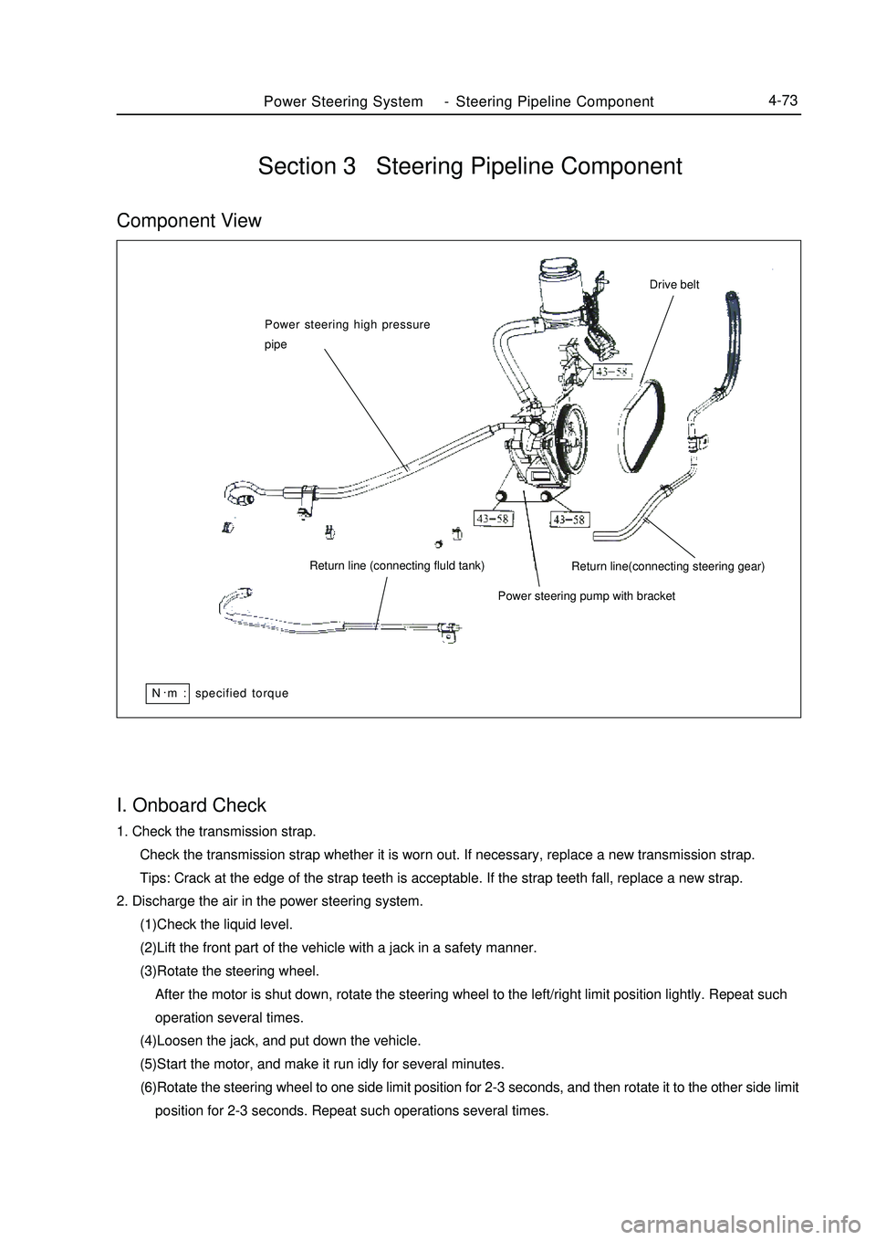
Power Steering System-Steering Pipeline Component4-73I. Onboard Check1. Check the transmission strap.
Check the transmission strap whether it is worn out. If necessary, replace a new transmission strap.
Tips: Crack at the edge of the strap teeth is acceptable. If the strap teeth fall, replace a new strap.
2. Discharge the air in the power steering system.
(1)Check the liquid level.
(2)Lift the front part of the vehicle with a jack in a safety manner.
(3)Rotate the steering wheel.
After the motor is shut down, rotate the steering wheel to the left/right limit position lightly. Repeat such
operation several times.
(4)Loosen the jack, and put down the vehicle.
(5)Start the motor, and make it run idly for several minutes.
(6)Rotate the steering wheel to one side limit position for 2-3 seconds, and then rotate it to the other side limit
position for 2-3 seconds. Repeat such operations several times.Section 3 Steering Pipeline ComponentComponent ViewPower steering high pressure
pipe
Return line (connecting fluld tank)
Power steering pump with bracketReturn line(connecting steering gear)Drive beltN.
m : specified torque
Page 162 of 416

Component ViewSection 4 Brake Master Cylinder AssemblyVacuum boosterBrake System -Brake Master Cylinder Assembly4-85Brake master cylinder
sub-assembly
Vacuum tube
Fluid level indicator lamp connector Manual Transmission
#1 clutch fluidr tank pipe No ABS
specified torqueN.
m :
Page 163 of 416

Component ViewBrake System -Brake Master Cylinder Assembly4-86With ABS:
Cover
Brake fluid reservoir
Strainer
Automatic Transmission
O-ring
Retaining ring
Pin
Straight pinPiston guide
block
Cup
Washer
#1 piston & Spring
#2 piston
Spring Hole connectorHole
connector
Master cylinder
Without ABS
Cover
Strainer
PinManual Transmission
O-ring
Retaining ring
Hole connector
Piston guide block
Cup
#1 piston & Spring
#2 piston & Spring
Washer
Piston limit bolt Master cylinder Hole connectorSpecified torque
Non-reusable parts
Lithium soap base glycol lube
Page 168 of 416

19151915131515
Fluid level indicator lamp connectorVacuum booster assembly
Gasket25Clip26 Clip Master cylinder
Manual Transmission
#1 clutch fluid tank oil pipe
HECU assemblyClipSection 5 Vacuum BoosterComponent ViewBrake System -Vacuum Booster4-91Battery
#2 relay box, engine chamber
Return spring
Pin
Push bar
U-connector Without ABSVacuum tube
Non-reusable parts
Lithium soap base glycol lubeSpecified torque
Page 170 of 416

Brake System -Vacuum Booster4-93Replacement1. Discharge the brake fluid.
Note:
Never spray the brake fluid on the paint surface, otherwise wash it immediately.
2. Unfix the clutch fluid tank pipe (manual transaxle).
3. Remove the brake master cylinder.
4. Remove the HECU assembly (with ABS).
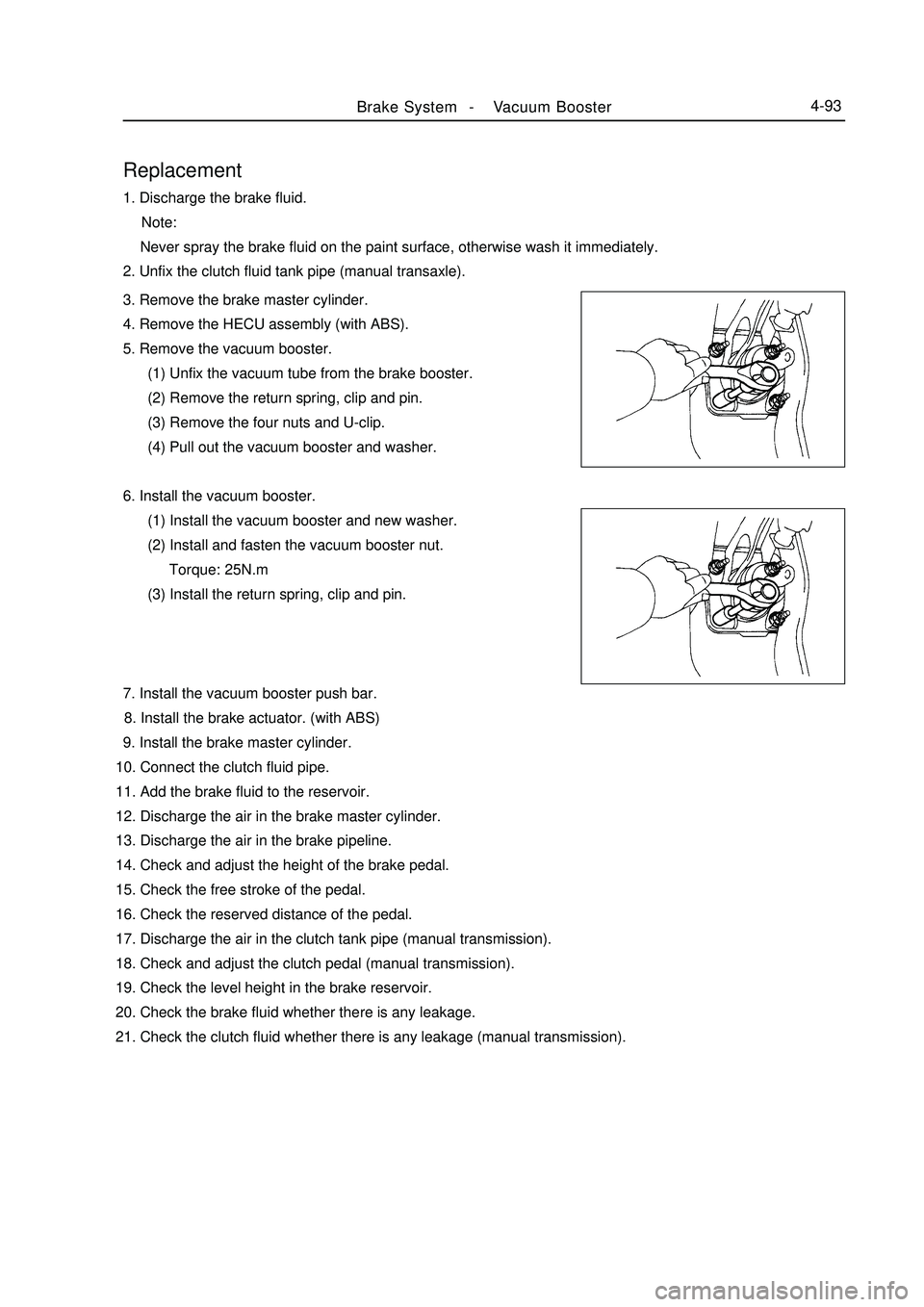
5. Remove the vacuum booster.
(1) Unfix the vacuum tube from the brake booster.
(2) Remove the return spring, clip and pin.
(3) Remove the four nuts and U-clip.
(4) Pull out the vacuum booster and washer.
6. Install the vacuum booster.
(1) Install the vacuum booster and new washer.
(2) Install and fasten the vacuum booster nut.
Torque: 25N.m
(3) Install the return spring, clip and pin.
7. Install the vacuum booster push bar.
8. Install the brake actuator. (with ABS)
9. Install the brake master cylinder.
10. Connect the clutch fluid pipe.
11. Add the brake fluid to the reservoir.
12. Discharge the air in the brake master cylinder.
13. Discharge the air in the brake pipeline.
14. Check and adjust the height of the brake pedal.
15. Check the free stroke of the pedal.
16. Check the reserved distance of the pedal.
17. Discharge the air in the clutch tank pipe (manual transmission).
18. Check and adjust the clutch pedal (manual transmission).
19. Check the level height in the brake reservoir.
20. Check the brake fluid whether there is any leakage.
21. Check the clutch fluid whether there is any leakage (manual transmission).
Page 198 of 416

c.Check voltage between terminals
Standard:Rotating wheel 7.5-9V
Below 0.5V0Voltage changes alternativelyCombination Instrument System -Malfunction Symptom Table and Troubleshooting5-11 Result and measures:
Normal, replace combination instrument assy.
Abnormal, repair or replace wiring harness or connector
2. Speedometer fails
Check
(1) Check combination instrument assy.
a. Remove combination instrument assy. , keep connection of connector.
b. Check on state
Check connection between terminals
Standard:Tester connection Conditions Standard condition
C 17- ground Turn ignition switch to ON position 7. 5-9V
Result and measures:
Abnormal, go to (2) Check combination instrument assy. speed input signal
Normal, go to (3) Check combination instrument assy.
(2) Check combination instrument assy. speed input signal
a. Check voltage
Prop up two front wheels
Push transmission lever to neutral position
Turn on ignition switch
turn front wheel slowly, measure the voltage between terminal C15 and terminal C16
Standard voltage is shown in the figure below:
Result and measures:
Normal, replace combination instrument assy.
Abnormal, check speed sensorTester connection Condition Standard condition
C 15-ground Normal ON
Page 199 of 416

Check voltage between terminals
Standard:7.5-9V
0Voltage changes alternatively5-12 b. Check speed sensor
Check on state
Check connection between terminals
Standard:Tester connection Conditions Standard condition
3- ground Turn ignition switch to ON position 7. 5-9VTester connection Condition Standard condition
2- ground Normal ON Result and measures:
Abnormal, repair or replace wiring harness or connector
Normal, check speed sensor output signal
c. Check speed sensor output signal
Check voltage
Prop up two front wheels
Push transmission lever to neutral position
Turn on ignition switch
Turn front wheel slowly, measure the voltage between terminal 1 and terminal 2
Standard voltage is shown in the figure below:
Rotating wheel Below 0.5V
Result and measures:
Normal, repair or replace wiring harness or connector
Abnormal, replace speed sensor
(3) Check combination instrument assy.
a. Remove combination instrument assy. , disconnect connector.
b. Check on status
Check connection between terminals
Standard:
Tester connection Condition Standard condition
C 13- ground Normal ONCombination Instrument System -Malfunction Symptom Table and Troubleshooting