cooling GEELY MK 2008 Workshop Manual
[x] Cancel search | Manufacturer: GEELY, Model Year: 2008, Model line: MK, Model: GEELY MK 2008Pages: 416, PDF Size: 25.19 MB
Page 5 of 416
Table of Contents II Section 4 Fuel Emission Control System ....................................................................... 3-18
Section 5 Carbon Canister Replacement ....................................................................... 3-19
Chapter 4 Exhaust System................................................................................................. 3-21
Chapter 5 Cooling System................................................................................................. 3-22
Section 1 System Inspection .......................................................................................... 3-22
Section 2 Radiator Replacement ................................................................................... 3-24
Chapter 6 Manual Transaxle Assembly............................................................................. 3-25
Section 1 Frequent Problem Diagnosis .......................................................................... 3-25
Section 2 Vehicle Speed Sensor Replacement ............................................................. 3-26
Section 3 Manual Transaxle Replacement ..................................................................... 3-27
Section 4 Transmission/Transaxle Case Oil Seal Replacement .................................... 3-28
Chapter 7 Automatic Transaxle Assembly........................................................................ 3-29
Section 1 Frequent Problems Diagnosis ........................................................................ 3-29
Section 2 Hydraulic Torque Converter and Transaxle .................................................... 3-30
Section 3 Differential Front Oil Seal (ATM) .................................................................... 3-33
Section 4 Neutral Switch Assembly ................................................................................ 3-35Part IV ChassisChapter 1 Transmission Control........................................................................................ 4-1
Section 1 Introduction of Transmission Control ............................................................. 4-1
Section 2 Cable Type Transmission Control .................................................................. 4-3
Section 3 Manual Transmission Shift Mechanism .......................................................... 4-5
Section 4 Automatic Transmission Shift Mechanism ...................................................... 4-7
Chapter 2 Accelerator Pedal Device................................................................................. 4-11
Section 1 Introduction of Accelerator Pedal ................................................................... 4-11
Chapter 3 Clutch Control System...................................................................................... 4-12
Section 1 Introduction of Clutch Centrol ......................................................................... 4-12
Section 2 Clutch Pedal ...................................................................................................4-13
Chapter 4 Propeller Shaft/Driveshaft................................................................................ 4-17
Section 1 Propeller Shaft, Driveshaft and Transaxle ..................................................... 4-17
Page 29 of 416
2-85. Actions to ensure vehicle working condition and safe driving.
(1) To make sure of driving safety, execute the following inspections before driving.
a. Inspect fuel level, and add fuel when necessary.
b. Inspect illuminating lights, turning signal lights, braking signal lights to see if they work.
c.Check the position of rearview mirrors.
d.Check if breaking system functions well.
e.Check if glass of all the lights, windshield is clean.
(2) Regular inspection Perform the following regular inspections to ensure the vehicle work condition and
driving safety.
a. Check engine oil level. Park the vehicle on flat road; check the oil level with engine oil level indicator
at least 10 minutes after the engine is stopped. The oil level should be between the two marks. If it is
lower than "L" mark, add some oil; if it is higher than "F" mark, there is excessive oil, so release it.
Or investigate the cause of high oil level.
The volume between the lowest oil level ("L") and highest oil level ("F") is 1.4L.
b. Check engine coolant level. Check the level when the engine is cool. The coolant level should be between
LOW and FULL. If it is lower than "LOW", add coolant. If the coolant is much lower than Min (every
coolant fill is more than 1L) or the vehicle requires frequent fills,investigate if there is any problem with
the cooling system.
To keep the function of coolant, replace coolant every two years at the beginning of cold winter.
c. Check brake and clutch fluid level (sharing a reservoir). Brake fluid level should between the Max and
Min marks. And it is better to keep it close to the Max mark. Add fluid in time when there is not enough
fluid.
d. Check power steering fluid tank. The level should be between Max and Min marks. Refill when there
is not enough steering fluid to avoid pump stuck. It is strictly prohibited to run the vehicle without
steering fluid in any circumstances.
e. Check the charging status of battery and if the connection of battery wires is good.
f. Check tire status and pressure
g. Check the status of wipers.
(3) Observe warning lights and indicators on instrument panel.
a. There are various warning lights and indicators on the instrument panel of MK-1 sedans to indicate and
warn abnormal operations of engine, braking, and charging systems.
b. Pay attention to these lights when driving.When the warning lights or indicators are on,stop the vehicle,
check the vehicle and resolve the causes to make sure the vehicle works well or drives safely.
6. Correct ways to use new cars
Reliability and stability of components in new cars and recently repaired cars still need to be confirmed, and
relative parts are not broken-in, so they must be used carefully to ensure driving safety, to avoid abnormal damage,
and to extend the useful life of the car.
(1) Before driving inspection The following inspections must be performed on the new car to ensure car safety
and reliable operation:
a. Check if instrument panel, warning lights, and indicator, front and rear wiper and washer, and switches
work.
b. Check if the fastening of driveline, steering, suspension, wheels and other connection parts is good.Usage and Maintenance of MK Series - Usage of MK Series
Page 30 of 416
2-9 c. Check levels of braking fluid, engine coolant, engine oil, transmission oil, power steering fluid, and
washing fluid to see if there is any leaking.
d. Inspect if brake pedal, clutch pedal, accelerator pedal, transmission shifter, steering wheel, choke are
loose or stuck. The free travel of clutch pedal is 5~15mm, the free travel of brake pedal is 1~6mm and
the free play of steering wheel is less than 30mm(measurement point at margin of steering wheel). if it
is out of this normal range, the clutch needs to be tuned.
e. Inspect if the connection of battery, lamps and signal lights are normal, and if the wire routing and
position are correct and not loose.
f. Inspect if the tire pressure is correct.
(2) On-road inspection If the inspection result of the above items is good, start the engine and test the car on
road, and perform the following inspections.
a. Acceleration pedal, see if the operation is smooth and if it is loose.
b. Clutch, see if there is any stuck or abnormal noise, and slip when driving.
c. Transmission,check if shifting is smooth,or rough and wrong shifting.Inspect if the display of A/T
shift lever is normal.
d. Steering, check if steering is light and smooth, and if the steering wheel turns back after steering.
e. Brake pedal, apply brake pedal to check if the braking functions well when vehicle speed is at
40km/h and if the vehicle runs off track.
f. Park brake, when parking brake handler is pulled, there should be 6~9 clicking sounds. Pull park brake
when vehicle is running at the speed of 20km/h and transmission is at neutral gear to see if it brakes.
g. Vehicle speed meter, observe the vehicle speed meter while driving. When speed changes, check if the
indicator is moving steadily or shakes.
h. Heating and air-conditioning.Try every control button to see if both heating and cooling system work
well.
i. Abnormal noise, listen carefully to see if there is any abnormal noise from engine, drive line system or
any other parts of the vehicle at a steady speed and during accelerating, and decelerating.
(3) Inspection after test ride check if there is anything abnormal in the vehicle while driving and conduct the
following inspections after the vehicle is parked.
a. Check electrical fan When engine coolant temperature is beyond 92.5°C, the radiator fan should be
running; When A/C is on and the pressure of refrigerant is more than 1.5 cooling ton, air conditioning
cooling fan should be running.
b. Check headlamp, method: park the car 5m away from the inspection surface (inspection board, curtain,
or wall) to the front bumper, and check if the beam from headlamp is good. The upper level if headlamp
should be 540mm above the ground, and the distance between headlamps on the two sides is 900mm.
c. Inspect engine idle speed,idle speed of hot engine is 800r/min±50r/min,when A/C compressor works,
the idle speed should be 900r/min±50r/min. If idle speed is abnormal, adjust the idle speed adjust
ment screw to adjust it.
(4) Usage of new cars in breaking-in period Follow the instructions below in the first 1500~2500km breaking
mileage to avoid wear and abnormal damage in breaking-in period, and to improve vehicle performance, fuel
economy and to extend vehicle useful life.
a. Drive steadily during breaking-in; do not accelerate harshly to avoid running engine at high speed.
Engine should not exceed 4500r/min in any gears. Especially at the early stage of breaking-in, vehicleUsage and Maintenance of MK Series - Usage of MK Series
Page 34 of 416
2-13For servicing items whose deadlines have expired, they should be maintained at the same intervals as before. The
intervals are recorded in maintenance schedule.
Rubber hoses
Used in cooling and heating system, braking and fuel-feeding systems should be inspected by qualified Geely
technicians according to Geely maintenance schedule.
There are all very important maintenance items. Hoses must be replaced immediately should there be any aging
or damage. Please pay attention, rubber hoses age as time goes by, and they may have problems of inflation, wear,
or crack.
Special Tips
If the vehicle is driven under one or more of the following circumstances, the maintenance items should be
carried out more frequently. See attached maintenance schedule.
A Road condition
1. drive on rough, muddy or skiddy roads
2. drive on dusty roads.
B driving condition
1. Repeat driving within 8km a few times, or when the outdoor temperature is below 0 degree centigrade.
2. Idle the car drive at a low speed for a long time, such as police car, taxi, or door to door delivery vehicles.
3. Continuously drive the car at high speed for more than 2 hours (80% of the max speed).IV. Regular inspections1. weekly schedule
inspect engine oil level and cleanness
inspect engine coolant level
inspect brake fluid level
inspect windshield wash fluid level
inspect power steering fluid level
2. monthly inspections
inspect water pump belt
inspect electrolyte level in battery
inspect tire air pressure and wear
inspect steering wheel
inspect brake
inspect acceleration pedal
3. inspection when driving (low speed)
inspect speed meter and water temperature
check steering wheel power and if vehicle runs off-track
check if the front wheels skid or swing
inspect if brake functions or if the vehicle runs off-track when brake is functioning
4. other inspection items
Eliminate problems immediately when there is anything abnormalUsage and Maintenance of MK Series - Maintenance Category and Content of MK Sedan
Page 44 of 416
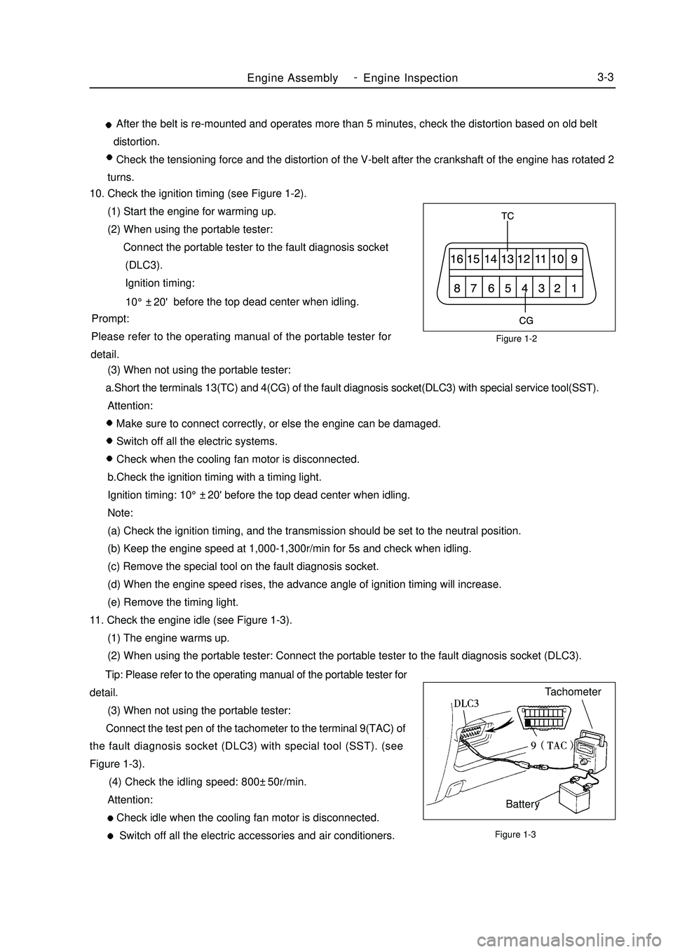
Figure 1-2
Figure 1-3Engine AssemblyEngine Inspection3-3 After the belt is re-mounted and operates more than 5 minutes, check the distortion based on old belt
distortion.
Check the tensioning force and the distortion of the V-belt after the crankshaft of the engine has rotated 2
turns.
10. Check the ignition timing (see Figure 1-2).
(1) Start the engine for warming up.
(2) When using the portable tester:
Connect the portable tester to the fault diagnosis socket
(DLC3).
Ignition timing:
before the top dead center when idling.
Prompt:
Please refer to the operating manual of the portable tester for
detail.
(3) When not using the portable tester:
a.Short the terminals 13(TC) and 4(CG) of the fault diagnosis socket(DLC3) with special service tool(SST).
Attention:
Make sure to connect correctly, or else the engine can be damaged.
Switch off all the electric systems.
Check when the cooling fan motor is disconnected.
b.Check the ignition timing with a timing light.
Ignition timing: 10°±20' before the top dead center when idling.
Note:
(a) Check the ignition timing, and the transmission should be set to the neutral position.
(b) Keep the engine speed at 1,000-1,300r/min for 5s and check when idling.
(c) Remove the special tool on the fault diagnosis socket.
(d) When the engine speed rises, the advance angle of ignition timing will increase.
(e) Remove the timing light.
11. Check the engine idle (see Figure 1-3).
(1) The engine warms up.
(2) When using the portable tester: Connect the portable tester to the fault diagnosis socket (DLC3).
Tip: Please refer to the operating manual of the portable tester for
detail.
(3) When not using the portable tester:
Connect the test pen of the tachometer to the terminal 9(TAC) of
the fault diagnosis socket (DLC3) with special tool (SST). (see
Figure 1-3).
(4) Check the idling speed: 800±50r/min.
Attention:
Check idle when the cooling fan motor is disconnected.
Switch off all the electric accessories and air conditioners.Tachometer
Battery10°±20' -
Page 63 of 416
2. Check the engine coolant quantity in the compensating tank.
The coolant level should be between LOW and FULL.
3. Check the coolant quality.
(1) Remove the radiator cover.
Do not remove the radiator cover when the engine and the radiator are still hot in order to avoid scalding
since the liquid vapor may inject.
(2) Check whether there are excessive deposit and rust or sundries around the radiator cover. The coolant is
not allowed to contact with oil.
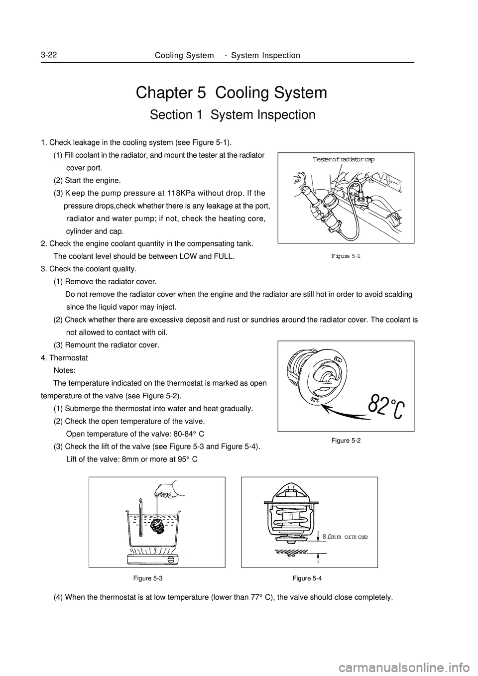
(3) Remount the radiator cover.Chapter 5 Cooling SystemSection 1 System Inspection1. Check leakage in the cooling system (see Figure 5-1).
(1) Fill coolant in the radiator, and mount the tester at the radiator
cover port.
(2) Start the engine.
(3) Keep the pump pressure at 118KPa without drop. If the
pressure drops,check whether there is any leakage at the port,
radiator and water pump; if not, check the heating core,
cylinder and cap.Figure 5-1
Figure 5-2
Figure 5-3 Figure 5-4 (4) When the thermostat is at low temperature (lower than 77°C), the valve should close completely.Cooling SystemSystem Inspection3-224. Thermostat
Notes:
The temperature indicated on the thermostat is marked as open
temperature of the valve (see Figure 5-2).
(1) Submerge the thermostat into water and heat gradually.
(2) Check the open temperature of the valve.
Open temperature of the valve: 80-84°C
(3) Check the lift of the valve (see Figure 5-3 and Figure 5-4).
Lift of the valve: 8mm or more at 95°CTester of radiator cap
8.0mm or more -
Page 64 of 416

Figure 5-6
Figure 5-7Above 93°CFigure 5-5Cooling SystemSystem Inspection3-235. Fan
(1) At low temperature (lower than 83°C), check the operation of
the cooling fan.
a. The ignition switch is set to ON.
b. The cooling fan should stop.
c. Disconnect the connector of the water temperature sensor.
(see Figure 5-5)
d.Touch the ground with a wire.
e.Check if the cooling fan rotates.
f. Re-connect the connector of the water temperature sensor.
(2) At high temperature (more than 93°C), check the operation of
the fan (see Figure 5-6).
a. Start the engine, and enable the coolant temperature higher
than 93°C.
b.Check whether the cooling fan rotates.
If not, replace the water temperature switch.
(3) Check the cooling fan (see Figure 5-7).
a. Disconnect the joint of the cooling fan.
b. Connect the battery and the ammeter with the connector.
c. The cooling fan should rotate stably and check the current
readings.
Standard current: 5.7-7.7A.
d. Connect the connector of the cooling fan.disconnectBattery Amper meter -
Page 65 of 416
Section 2 Radiator Replacement1. Replace the radiator.
(1) Open the radiator cover.
(2) Open the water drain valve and discharge the coolant.
(3) Disconnect the water inlet pipe of the radiator.
(4) Disconnect the water outlet pipe of the radiator.
(5) Disconnect the input pipe of the oil cooler of the automatic transmission (automatic transmission).
(6) Disconnect the output pipe of the oil cooler of the automatic transmission (automatic transmission).
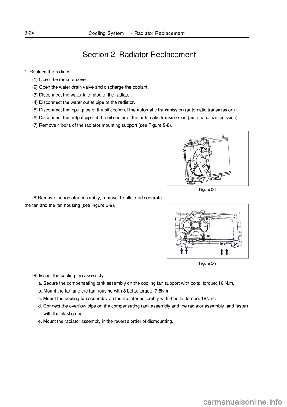
(7) Remove 4 bolts of the radiator mounting support (see Figure 5-8).Figure 5-8
Figure 5-9Cooling SystemRadiator Replacement3-24 (8)Remove the radiator assembly, remove 4 bolts, and separate
the fan and the fan housing (see Figure 5-9).
(9) Mount the cooling fan assembly.
a. Secure the compensating tank assembly on the cooling fan support with bolts; torque: 16 N.m.
b. Mount the fan and the fan housing with 3 bolts; torque: 7.5N.m.
c. Mount the cooling fan assembly on the radiator assembly with 3 bolts; torque: 16N.m.
d. Connect the overflow pipe on the compensating tank assembly and the radiator assembly, and fasten
with the elastic ring.
e. Mount the radiator assembly in the reverse order of dismounting. -
Page 71 of 416
The valve body fails.
12. The vehicle shifts before or after some gear points in the running status.
The vehicle switch or parking switch fails.
13. The vehicle has poor acceleration in running.
(1)The clutch or brake fails.
(2)The engine system fails.
14. The vehicle vibrates when it runs at a constant speed or accelerating speed.
(1)The hydraulic torque clutch pressure or hydraulic torque meter fails.
(2)The engine system or valve fails.
15. The acceleration switch system fails.
(1)The acceleration switch or ignition switch fails.
(2)The connector or automatic transmission control unit fails.I. Automatic transmissions Removal1. Put the select lever in "N" position
2. Remove 3 bolts of the flexibility plate (engine side)
3. Remove starter and 2 cooling hoses.
4. Disconnect neutral switch connector and odometer sensor.
5. Loosen the drain screw under the housing to bleed ATF and tighten the drain screw with sealing glue when
assembling. Tightening torque is 29~35N.m
6. Loosen the locking bolt for select lever cable.
7. Remove Drive Shaft LH&RH, using plastic stopper in the oil sealing of differential.
8. Detach suspension bolts.
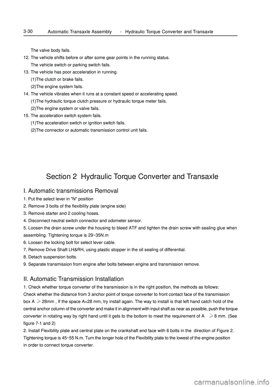
9. Separate transmission from engine after bolts between engine and transmission remove.II. Automatic Transmission Installation1. Check whether torque converter of the transmission is in the right position, the methods as follows:
Check whether the distance from 3 anchor point of torque converter to front contact face of the transmission
box A 28mm , If the space A<28 mm, try install again. The way to install is that left hand catch hold of the
central anchor column of the converter and make it in alignment with input shaft as near as possible, push the torque
converter in rotating way by right hand until it gets to the bottom to meet the requirement of A 28 mm. (See
figure 7-1 and 2)
2. Install Flexibility plate and central plate on the crankshaft end face with 6 bolts in the direction of Figure 2.
Tightening torque is 45~55 N.m. Turn the longer hole of the Flexibility plate to the lowest of the engine position
in order to connect torque converter.Section 2 Hydraulic Torque Converter and TransaxleAutomatic Transaxle Assembly Hydraulic Torque Converter and Transaxle3-30 -
Page 72 of 416
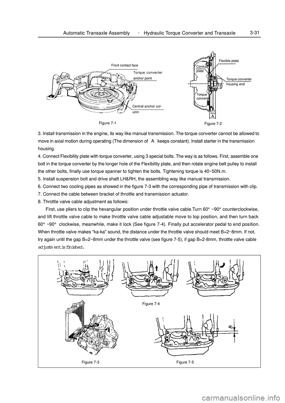
Figure 7-3Automatic Transaxle Assembly Hydraulic Torque Converter and Transaxle3-31Figure 7-5 Figure 7-4Figure 7-1
Figure 7-23. Install transmission in the engine, its way like manual transmission. The torque converter cannot be allowed to
move in axial motion during operating (The dimension of A keeps constant). Install starter in the transmission
housing.
4. Connect Flexibility plate with torque converter, using 3 special bolts. The way is as follows. First, assemble one
bolt in the torque converter by the longer hole of the Flexibility plate, and then rotate engine belt pulley to install
the other bolts, finally use torque spanner to tighten the bolts. Tightening torque is 40~50N.m.
5. Install suspension bolt and drive shaft LH&RH, the assembling way like manual transmission.
6. Connect two cooling pipes as showed in the figure 7-3 with the corresponding pipe of transmission with clip.
7. Connect the cable between bracket of throttle and transmission actuator.
8. Throttle valve cable adjustment as follows:
First, use pliers to clip the hexangular position under throttle valve cable.Turn 60°~90°counterclockwise,
and lift throttle valve cable to make throttle valve cable adjustable move to top position, and then turn back
60°~90° clockwise, meanwhile, make it lock (See figure 7-4). Finally put accelerator pedal to end position.
When throttle valve makes "ka-ka" sound, the distance under the throttle valve should meet B=2~8mm. If not,
try again until the gap B=2~8mm under the throttle valve (see figure 7-5), if gap B=2-8mm, throttle valve cable
adjustment is finished.Central
plateFlexible plate
Torque converter
housing end
Torque
converterFront contact face
Torque converter
anchor point
Central anchor col-
umn -