length GEELY MK 2008 Workshop Manual
[x] Cancel search | Manufacturer: GEELY, Model Year: 2008, Model line: MK, Model: GEELY MK 2008Pages: 416, PDF Size: 25.19 MB
Page 22 of 416

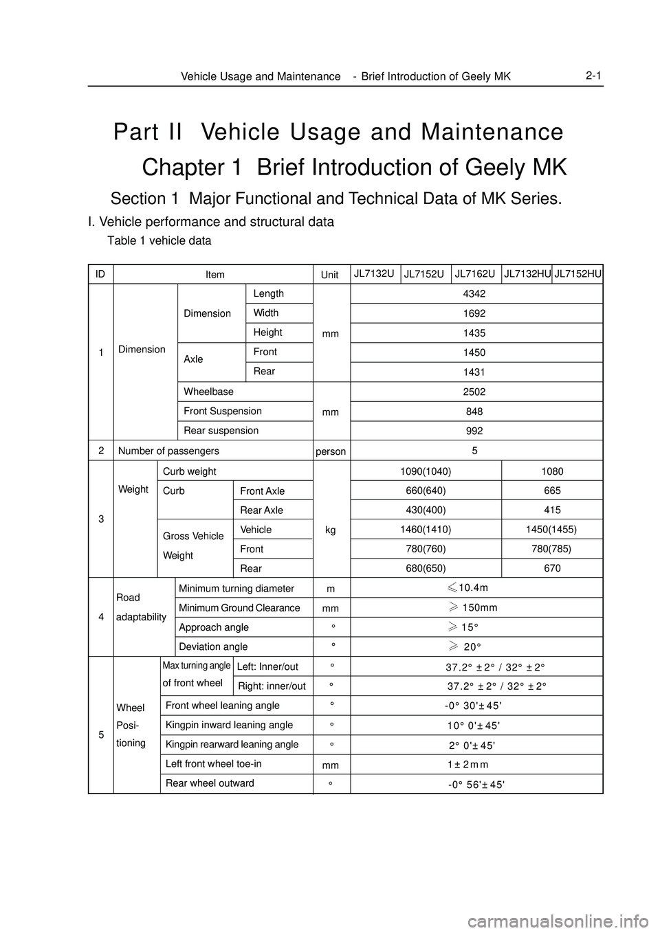
Part II Vehicle Usage and MaintenanceChapter 1 Brief Introduction of Geely MKSection 1 Major Functional and Technical Data of MK Series.I. Vehicle performance and structural data Table 1 vehicle dataVehicle Usage and Maintenance - Brief Introduction of Geely MK2-1JL7162U
JL7152U JL7132UUnit
mm
mm
person
kg
m
mm
°
mm Item ID
1
2
3
4
5DimensionDimension
Axle4342
1692
1435
1450
1431
2502
848
992
5
150mm
15°
20°
-0°30'±45'
1±2mmLength
Width
Height
Front
Rear
Wheelbase
Front Suspension
Rear suspension
Number of passengersWeightCurb weight
Front Axle
Rear Axle
Vehicle
Front
Rear CurbGross Vehicle
Weight
Road
adaptabilityMinimum turning diameter
Minimum Ground Clearance
Approach angle
Deviation angleWheel
Posi-
tioningLeft: Inner/out
Right: inner/outMax turning angleof front wheel
Front wheel leaning angle
Kingpin inward leaning angle
Kingpin rearward leaning angle
Left front wheel toe-in
Rear wheel outwardJL7132HU JL7152HU1090(1040)
660(640)
430(400)
1460(1410)
780(760)
680(650)1080
665
415
1450(1455)
780(785)
670 10.4m
°
°
°
°
°
°°37.2°±2°/ 32°±2°
37.2°±2°/ 32°±2°
2°0'±45' 10°0'±45'
-0°56'±45'
Page 62 of 416

Chapter IV Exhaust SystemComponent View
Replace1. Remove the tail exhaust pipe assembly.
Remove 2 bolts and the tail exhaust pipe assembly.
2. Remove the middle exhaust pipe assembly.
Replace the exhaust system.
Remove 2 bolts and the middle exhaust pipe assembly.
3. Remove the front exhaust pipe assembly.
Remove 2 bolts and the front exhaust pipe assembly.
4. Mount the front exhaust pipe assembly.
Measure the free length of the spring with a slide caliper.
Free length: 42mmFigure 4-1
Figure 4-2Exhaust SystemExhaust System3-21Center Muffer
Front MufferRear MufferThree-way Catalytic ConverterRear Rubber
BracketFront Rubber Bracket Mount the front exhaust pipe on the exhaust manifold with new washer.
Notes:
Do not use the removed washer any more.
5. Mount the front exhaust pipe assembly.
Torque: 43N.m
6. Mount the middle exhaust pipe assembly.
Mount the middle exhaust pipe on the front exhaust pipe with new washer.
Torque: 44N.m
7. Mount the tail exhaust pipe assembly.
Mount the tail exhaust pipe on the middle exhaust pipe with new washer. (see Figure 4-2).
Torque: 43N.m
8. Check exhaust leakage.washer Tail pipe side Suitable for 1.5L/1.6L(Tight coupling)
Suitable for 1.3L/1.5L(Non-tight coupling) -
Page 120 of 416

Section 3 Front Wheel AlignmentAdjustment:1. Check tire
2. Measure the vehicle height
Vehicle height:Tire sizeFront1 (mm)Rear2 (mm)
175 / 65R14 82H191 265
185 / 60R15 84H192 265Front Suspension System-Front Wheel Alignment4-43 1.front measure point
Measure the distance between the ground and the front underside
suspension mounting bolt center
2.rear measure point
Measure the distance between the ground and the rear axle beam mounting bolt center
Notice:
Before the wheel alignment,adjust the body to the specified height.If the body height is out of spec,adjustment
shall be done by pressing or raising vehicle body.
3. Check the Toe-in
Toe-in:
If the toe-in is out of spec, adjust the ends of rack.
4. Adjust the Toe-in
(1) Remove the clamp of the rack boot
(2) Loose the jam nut of tie rod
(3) Adjust the Toe-in by rotating the same turns of both ends of
rack.
Tips: Adjust the toe-in to the intermediate value of spec.
(4)Make sure the same length for both ends
The length difference of left and right: 1.5mm or smaller
(5)Tighten the jam nut of the tie rod
Torque: 47N.m
(6)Seat the boot and crimp the clamp
Tips: rack boot must not be twistedFront
Rear
Front
Page 121 of 416

Camber angle
Left-right wheel deviation
Caster angle
Manual steering
Power steering
Left-right wheel deviation
Kingpin inclination
Manual steering
Power steering
Left-right wheel deviation-0°30' ± 45' (-0.5° ± 0.75°)
45'(0.75°) or smaller
1°46' ± 45' (1.76° ± 0.75°)
45' (0.75°) or smaller
9°54' ± 45' (9.90° ± 0.75°)
45' (0.75°) or lessFront Suspension SystemFront Wheel Alignment4-44Manual steering Power steering
Inside wheel 9-137.2°±2°
Outside wheel32°±2° 32°±2°5. Check the steering angle of wheel
Fully steer the wheel and measure the angle
The angle of wheel:
If the kingpin caster angle and the kingpin inclination be out of spec, check the damage and abrasion of
suspension parts after the correct adjustment of camber angle. If there is deviation with spec for right and left wheel angle, check the rack length of left and right ends.
6. Check the camber, caster and steering axle inclination angle
7. Adjust the camber angle
Notice:
Check the toe-in after adjust the camber angle
(1)Remove the front wheel
(2)Remove the two nuts under the shock absorber
If you need to reuse the bolts and nuts, apply the engine oil on
the nut thread
(3)Clear the mounting surface of the knuckle and shock absorber.Front
Inside
Outside
meter
locator-9-1
Page 167 of 416

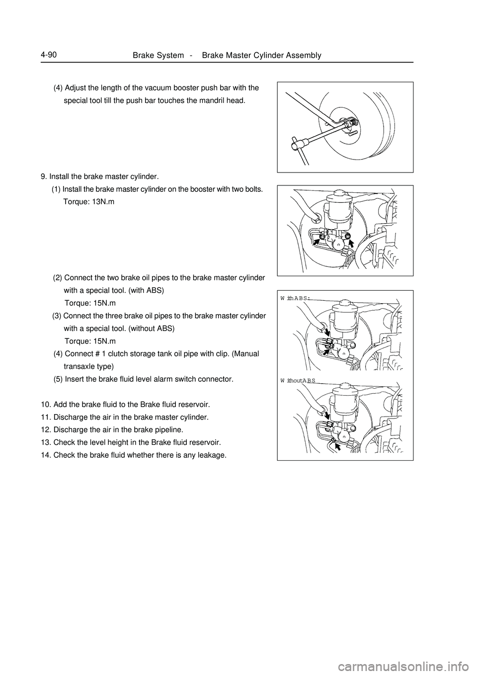
Brake System -Brake Master Cylinder Assembly4-90 (4) Adjust the length of the vacuum booster push bar with the
special tool till the push bar touches the mandril head.
9. Install the brake master cylinder.
(1) Install the brake master cylinder on the booster with two bolts.
Torque: 13N.m
(2) Connect the two brake oil pipes to the brake master cylinder
with a special tool. (with ABS)
Torque: 15N.m
(3) Connect the three brake oil pipes to the brake master cylinder
with a special tool. (without ABS)
Torque: 15N.m
(4) Connect # 1 clutch storage tank oil pipe with clip. (Manual
transaxle type)
(5) Insert the brake fluid level alarm switch connector.
10. Add the brake fluid to the Brake fluid reservoir.
11. Discharge the air in the brake master cylinder.
12. Discharge the air in the brake pipeline.
13. Check the level height in the Brake fluid reservoir.
14. Check the brake fluid whether there is any leakage.With ABS:
Without ABS
Page 177 of 416

Repair Repair the right side as the steps in the left side.
1. Check the thickness of the brake shoe lining.
Remove the hole plug, and check the thickness of the brake shoe
lining through the hole.
If the thickness is less than the minimum thickness, replace a new
brake shoe.
Minimum Thickness: 1.0mm
2. Remove the rear wheel.
3. Discharge the brake fluid.
Note:
Never spray the brake fluid on the paint surface, otherwise wash
it immediately.
4. Remove the rear brake drum.
(1) Loosen the parking brake rod, and remove the brake drum.
Tips: If the brake drum can't be removed easily, carry out the
following steps.
(2) Remove the hole plug, and insert a screwdriver through the
backboard to separate the brake automatic adjustment rod
and the adjustor.
(3) Rotate the adjustment wheel to reduce the length of the
adjustor with another screwdriver.
5. Check the inner diameter of the brake drum.
Measure the inner diameter of the brake drum with a brake drum
gauge or equivalent.
Standard Inner Diameter: 200.0mm
Maximum Inner Diameter: 201.0mm
6. Separate the left positioning post of the parking brake shoe.
Remove the extension spring from the front/rear brake shoe with
a special tool, and separate the left positioning post of the parking
brake shoe.
Note:
Be careful not to damage to the dust shield of the brake cylinder.
7. Remove the front brake shoe.
(1) Remove the end cap, set spring and pin with a special tool.
(2) Unfix the return spring, and remove the front brake shoe.
(3) Remove the left positioning post of the parking brake shoe.Brake System -Rear Brake Drum4-100Rotate
Page 396 of 416

1. Material of Punch Piece
In order to improve the body's rigidity, high-strength steel plates are used at many key parts on the body. For
the parts under forces, reinforced measures are carried out. (Fig. 5-36)Fig. 5-36 High-strength Steel Panel
1. Engine compartment hood outside panel
2. Left/right fender
3. Left/right mid-door post inside panel
4. Luggage cover outside panel
5. Left/right door outside panel12
3
45Body Repair -Features and Composition of Automobile Body7-24Fig. 5-35 Outline & DimensionsSection 4 Features and Composition of Automobile BodyI. Body Feature The body is an integral structure. Its main structure also is a frame, which can carry all loads. The vehicle is
designed with three compartments and five doors. With the same overall length, the space is utilized fully, which
is helpful to arrangement of passengers. (Fig. 5-35)
14351431
1934.5 1450
4343 848 2502 992