oil type GEELY MK 2008 Workshop Manual
[x] Cancel search | Manufacturer: GEELY, Model Year: 2008, Model line: MK, Model: GEELY MK 2008Pages: 416, PDF Size: 25.19 MB
Page 5 of 416
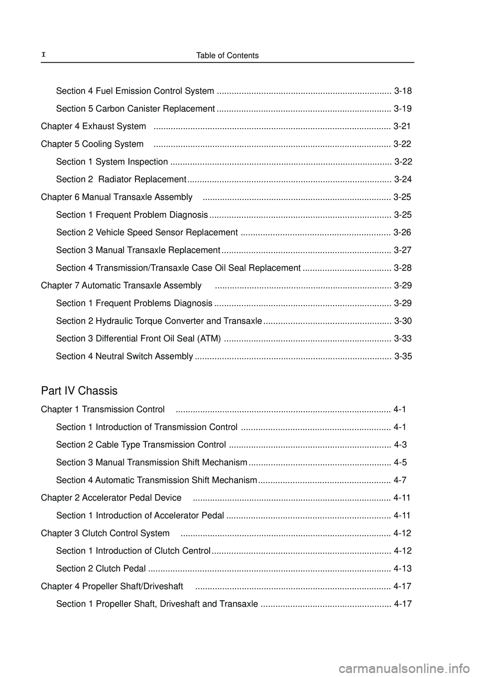
Table of Contents II Section 4 Fuel Emission Control System ....................................................................... 3-18
Section 5 Carbon Canister Replacement ....................................................................... 3-19
Chapter 4 Exhaust System................................................................................................. 3-21
Chapter 5 Cooling System................................................................................................. 3-22
Section 1 System Inspection .......................................................................................... 3-22
Section 2 Radiator Replacement ................................................................................... 3-24
Chapter 6 Manual Transaxle Assembly............................................................................. 3-25
Section 1 Frequent Problem Diagnosis .......................................................................... 3-25
Section 2 Vehicle Speed Sensor Replacement ............................................................. 3-26
Section 3 Manual Transaxle Replacement ..................................................................... 3-27
Section 4 Transmission/Transaxle Case Oil Seal Replacement .................................... 3-28
Chapter 7 Automatic Transaxle Assembly........................................................................ 3-29
Section 1 Frequent Problems Diagnosis ........................................................................ 3-29
Section 2 Hydraulic Torque Converter and Transaxle .................................................... 3-30
Section 3 Differential Front Oil Seal (ATM) .................................................................... 3-33
Section 4 Neutral Switch Assembly ................................................................................ 3-35Part IV ChassisChapter 1 Transmission Control........................................................................................ 4-1
Section 1 Introduction of Transmission Control ............................................................. 4-1
Section 2 Cable Type Transmission Control .................................................................. 4-3
Section 3 Manual Transmission Shift Mechanism .......................................................... 4-5
Section 4 Automatic Transmission Shift Mechanism ...................................................... 4-7
Chapter 2 Accelerator Pedal Device................................................................................. 4-11
Section 1 Introduction of Accelerator Pedal ................................................................... 4-11
Chapter 3 Clutch Control System...................................................................................... 4-12
Section 1 Introduction of Clutch Centrol ......................................................................... 4-12
Section 2 Clutch Pedal ...................................................................................................4-13
Chapter 4 Propeller Shaft/Driveshaft................................................................................ 4-17
Section 1 Propeller Shaft, Driveshaft and Transaxle ..................................................... 4-17
Page 25 of 416
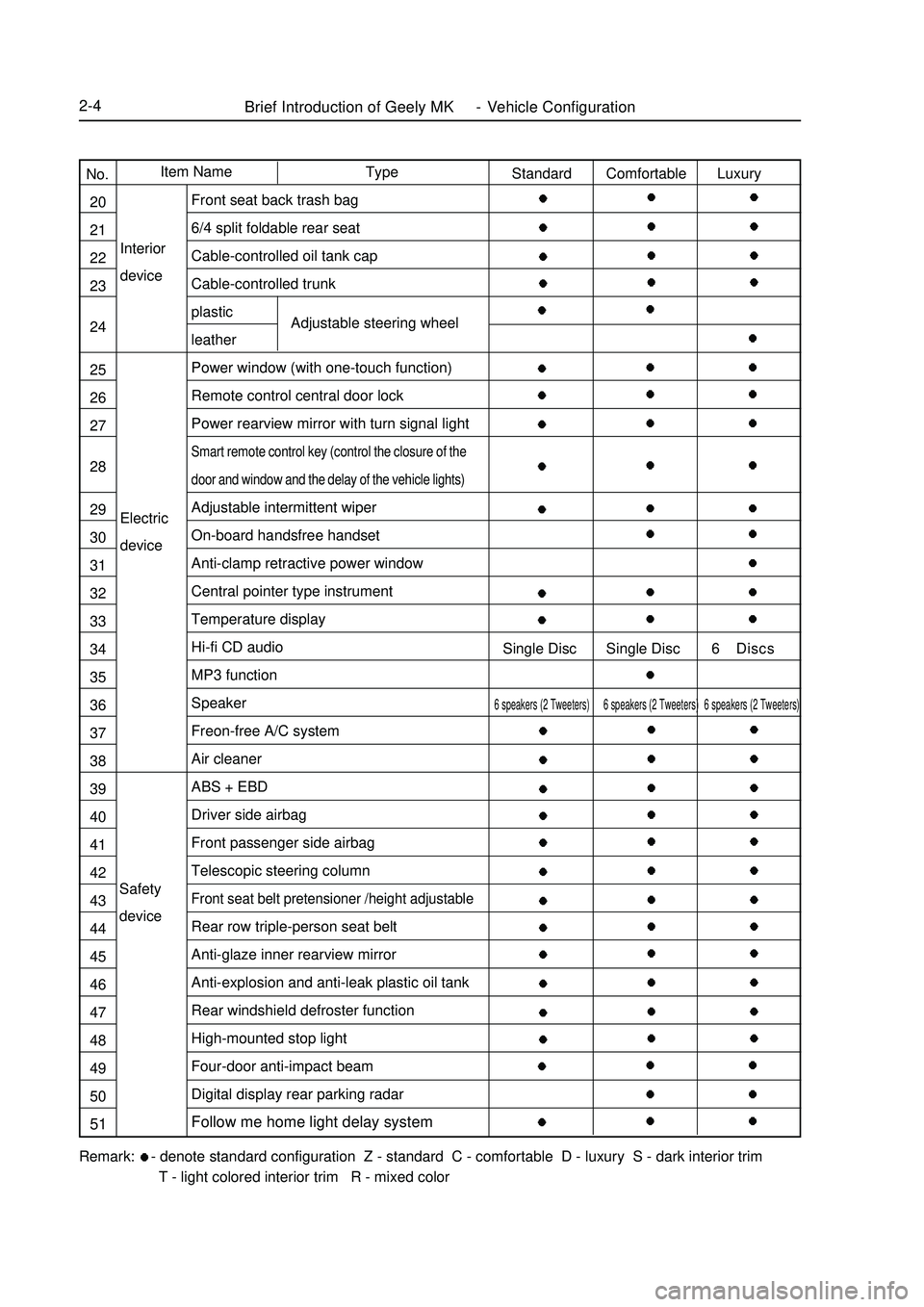
Brief Introduction of Geely MK - Vehicle Configuration2-4Electric
deviceInterior
deviceAdjustable steering wheelRemark: - denote standard configuration Z - standard C - comfortable D - luxury S - dark interior trim
T - light colored interior trim R - mixed colorType Item Name
No.
20
21
22
23
24
25
26
27
28
29
30
31
32
33
34
35
36
37
38
39
40
41
42
43
44
45
46
47
48
49
50
51Standard Comfortable Luxury
Single Disc Single Disc 6 Discs6 speakers (2 Tweeters) 6 speakers (2 Tweeters) 6 speakers (2 Tweeters)Front seat back trash bag
6/4 split foldable rear seat
Cable-controlled oil tank cap
Cable-controlled trunk
plastic
leather
Power window (with one-touch function)
Remote control central door lock
Power rearview mirror with turn signal lightSmart remote control key (control the closure of the
door and window and the delay of the vehicle lights)Adjustable intermittent wiper
On-board handsfree handset
Anti-clamp retractive power window
Central pointer type instrument
Temperature display
Hi-fi CD audio
MP3 function
Speaker
Freon-free A/C system
Air cleaner
ABS + EBD
Driver side airbag
Front passenger side airbag
Telescopic steering columnFront seat belt pretensioner /height adjustableRear row triple-person seat belt
Anti-glaze inner rearview mirror
Anti-explosion and anti-leak plastic oil tank
Rear windshield defroster function
High-mounted stop light
Four-door anti-impact beam
Digital display rear parking radar
Follow me home light delay systemSafety
device
Page 115 of 416
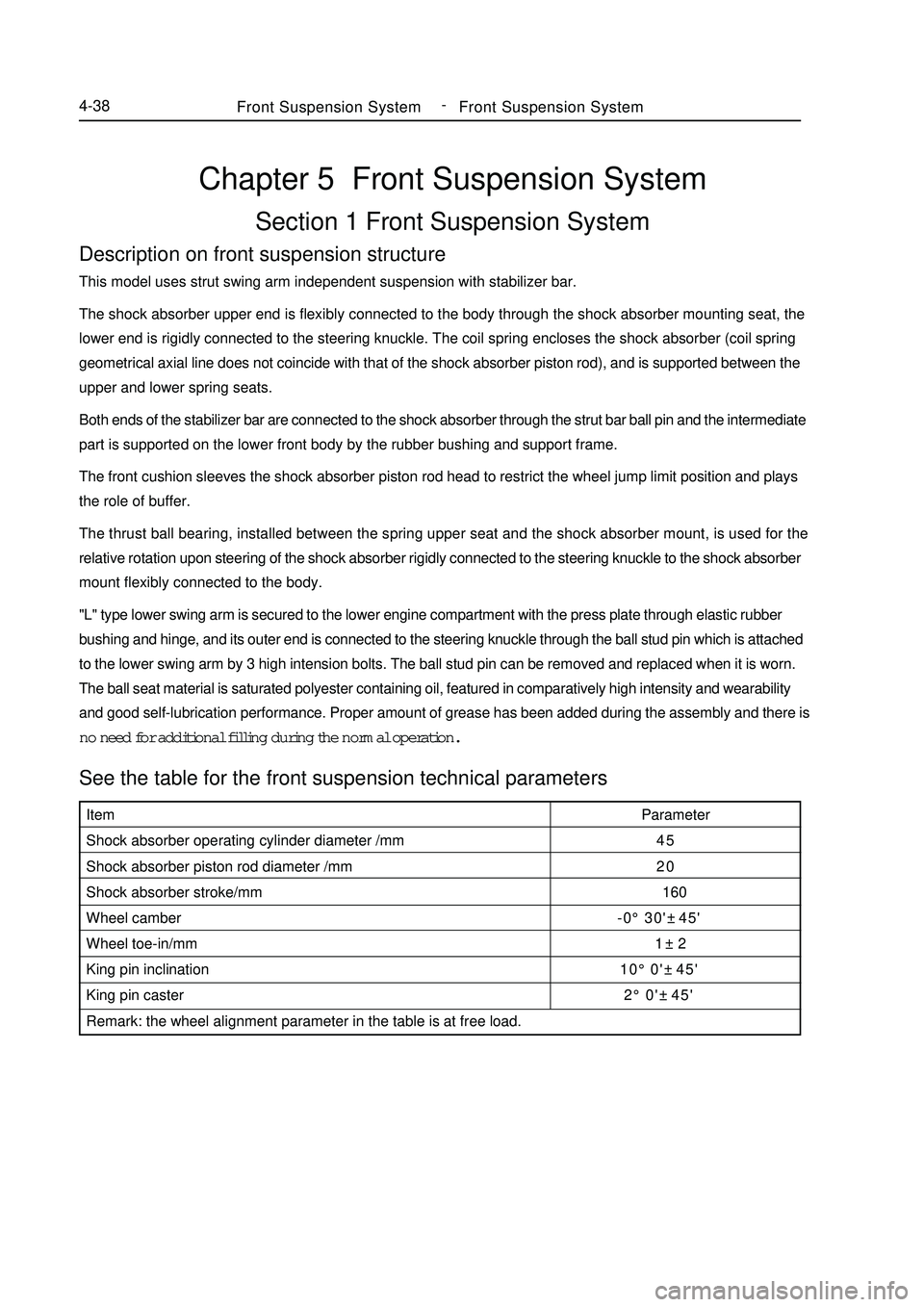
Chapter 5 Front Suspension SystemSection 1 Front Suspension SystemDescription on front suspension structureThis model uses strut swing arm independent suspension with stabilizer bar.
The shock absorber upper end is flexibly connected to the body through the shock absorber mounting seat, the
lower end is rigidly connected to the steering knuckle. The coil spring encloses the shock absorber (coil spring
geometrical axial line does not coincide with that of the shock absorber piston rod), and is supported between the
upper and lower spring seats.
Both ends of the stabilizer bar are connected to the shock absorber through the strut bar ball pin and the intermediate
part is supported on the lower front body by the rubber bushing and support frame.
The front cushion sleeves the shock absorber piston rod head to restrict the wheel jump limit position and plays
the role of buffer.
The thrust ball bearing, installed between the spring upper seat and the shock absorber mount, is used for the
relative rotation upon steering of the shock absorber rigidly connected to the steering knuckle to the shock absorber
mount flexibly connected to the body.
"L" type lower swing arm is secured to the lower engine compartment with the press plate through elastic rubber
bushing and hinge, and its outer end is connected to the steering knuckle through the ball stud pin which is attached
to the lower swing arm by 3 high intension bolts. The ball stud pin can be removed and replaced when it is worn.
The ball seat material is saturated polyester containing oil, featured in comparatively high intensity and wearability
and good self-lubrication performance. Proper amount of grease has been added during the assembly and there is
no need for additional filling during the normal operation.See the table for the front suspension technical parametersFront Suspension SystemFront Suspension System4-38Item
Shock absorber operating cylinder diameter /mm
Shock absorber piston rod diameter /mm
Shock absorber stroke/mm
Wheel camber
Wheel toe-in/mm
King pin inclination
King pin caster
Remark: the wheel alignment parameter in the table is at free load.Parameter
45
20
160
-0°30'±45'
1±2
10°0'±45'
2°0'±45' -
Page 167 of 416
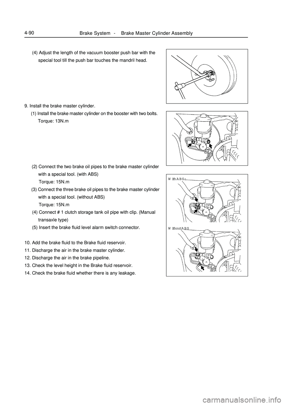
Brake System -Brake Master Cylinder Assembly4-90 (4) Adjust the length of the vacuum booster push bar with the
special tool till the push bar touches the mandril head.
9. Install the brake master cylinder.
(1) Install the brake master cylinder on the booster with two bolts.
Torque: 13N.m
(2) Connect the two brake oil pipes to the brake master cylinder
with a special tool. (with ABS)
Torque: 15N.m
(3) Connect the three brake oil pipes to the brake master cylinder
with a special tool. (without ABS)
Torque: 15N.m
(4) Connect # 1 clutch storage tank oil pipe with clip. (Manual
transaxle type)
(5) Insert the brake fluid level alarm switch connector.
10. Add the brake fluid to the Brake fluid reservoir.
11. Discharge the air in the brake master cylinder.
12. Discharge the air in the brake pipeline.
13. Check the level height in the Brake fluid reservoir.
14. Check the brake fluid whether there is any leakage.With ABS:
Without ABS
Page 259 of 416
Item
Temperature regulation method
CompressorNominal refrigerating capacity / w
Displacement / (ml /r)
Model
Power consumed by magnetic clutch /W
Lubricating oil / ml
BlowerMaximum air quantity / (m3/h)
Air regulation
Motor power / W
Dimension /mm
Heat exchange quantity / W
Fan motor current / A
Fan motor revolution / (r/min)
Dimension /mm
Refrigerating capacity /W
Thermostatic expansion valve Condenser
Evaporator
Driving belt
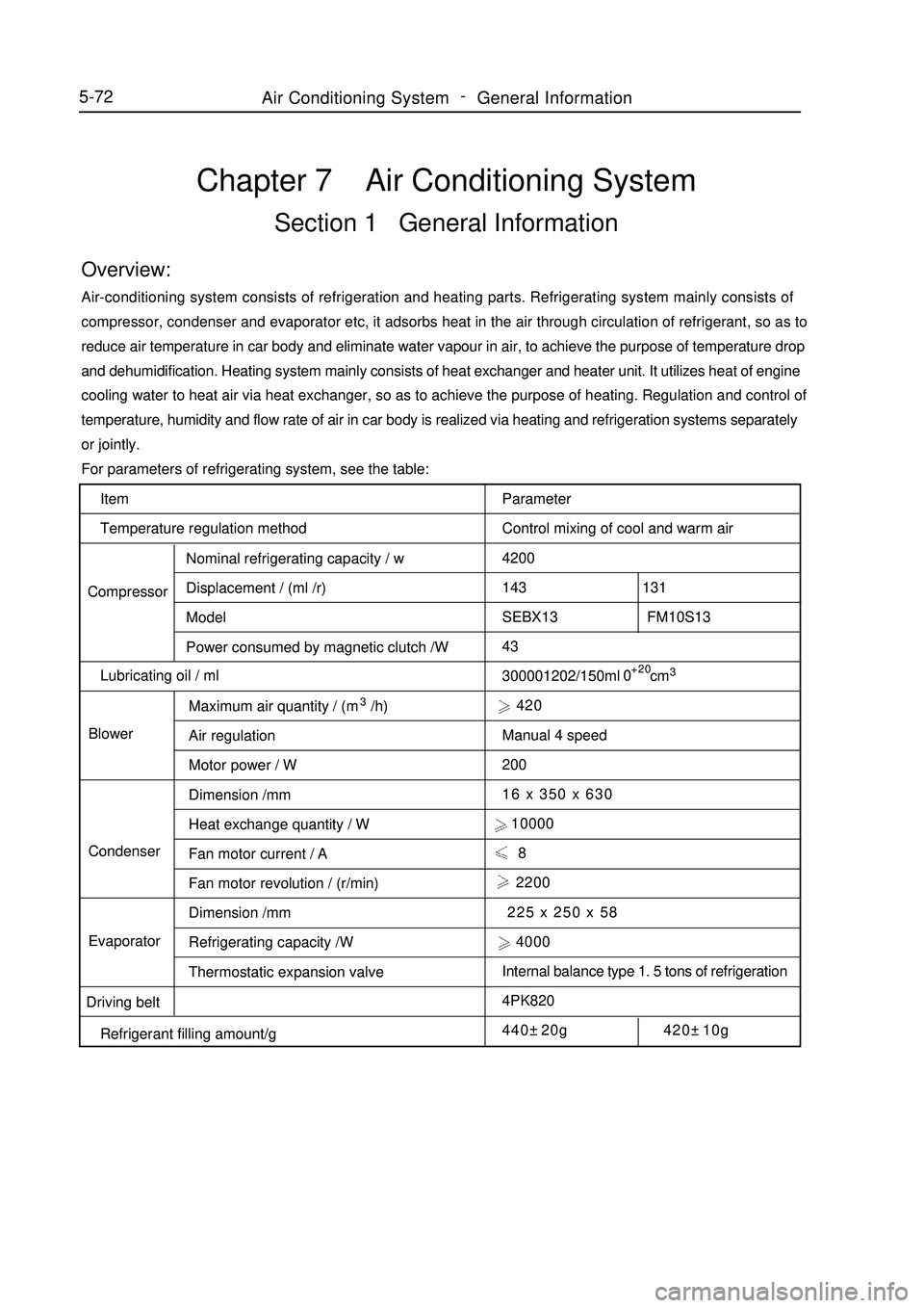
Refrigerant filling amount/gChapter 7 Air Conditioning SystemSection 1 General InformationOverview:Air-conditioning system consists of refrigeration and heating parts. Refrigerating system mainly consists of
compressor, condenser and evaporator etc, it adsorbs heat in the air through circulation of refrigerant, so as to
reduce air temperature in car body and eliminate water vapour in air, to achieve the purpose of temperature drop
and dehumidification. Heating system mainly consists of heat exchanger and heater unit. It utilizes heat of engine
cooling water to heat air via heat exchanger, so as to achieve the purpose of heating. Regulation and control of
temperature, humidity and flow rate of air in car body is realized via heating and refrigeration systems separately
or jointly.
For parameters of refrigerating system, see the table:
Parameter
Control mixing of cool and warm air
4200
143 131
SEBX13 FM10S13
43
300001202/150ml cm3 420
Manual 4 speed
200
16 x 350 x 630
10000
8
2200
225 x 250 x 58
4000
Internal balance type 1. 5 tons of refrigeration
4PK820
440±20g 420±10g+20
05-72Air Conditioning System -
General Information
Page 307 of 416
Fault symptom
Flameout, poor idle speedChapter 9 Engine EFI SystemI. Outline This system includes sensor that detects engine functioning. Engine ECU utilizes sensors installed at differ-
ent parts of engine to measure various working parameters of engine, accurately control oil injection quantity
according to control procedure set in engine electronic control unit, so engine could work in optimum mode
under various operating conditions, i. e. optimal power output, the most economical oil consumption, optimal
exhaust emissions. Engine ECU is capable of start up control, idle speed closed-loop control, air fuel ratio
closed-loop control, canister control, transient operation control, angle of ignition control, knocking control, air
conditioning control, coasting fuel cutoff and overspeed fuel cutoff control, ternary catalyst heating and protec-
tion control, system self-diagnosis etc.II. Inspection of control element1. Manifold intake pressure temperature sensor
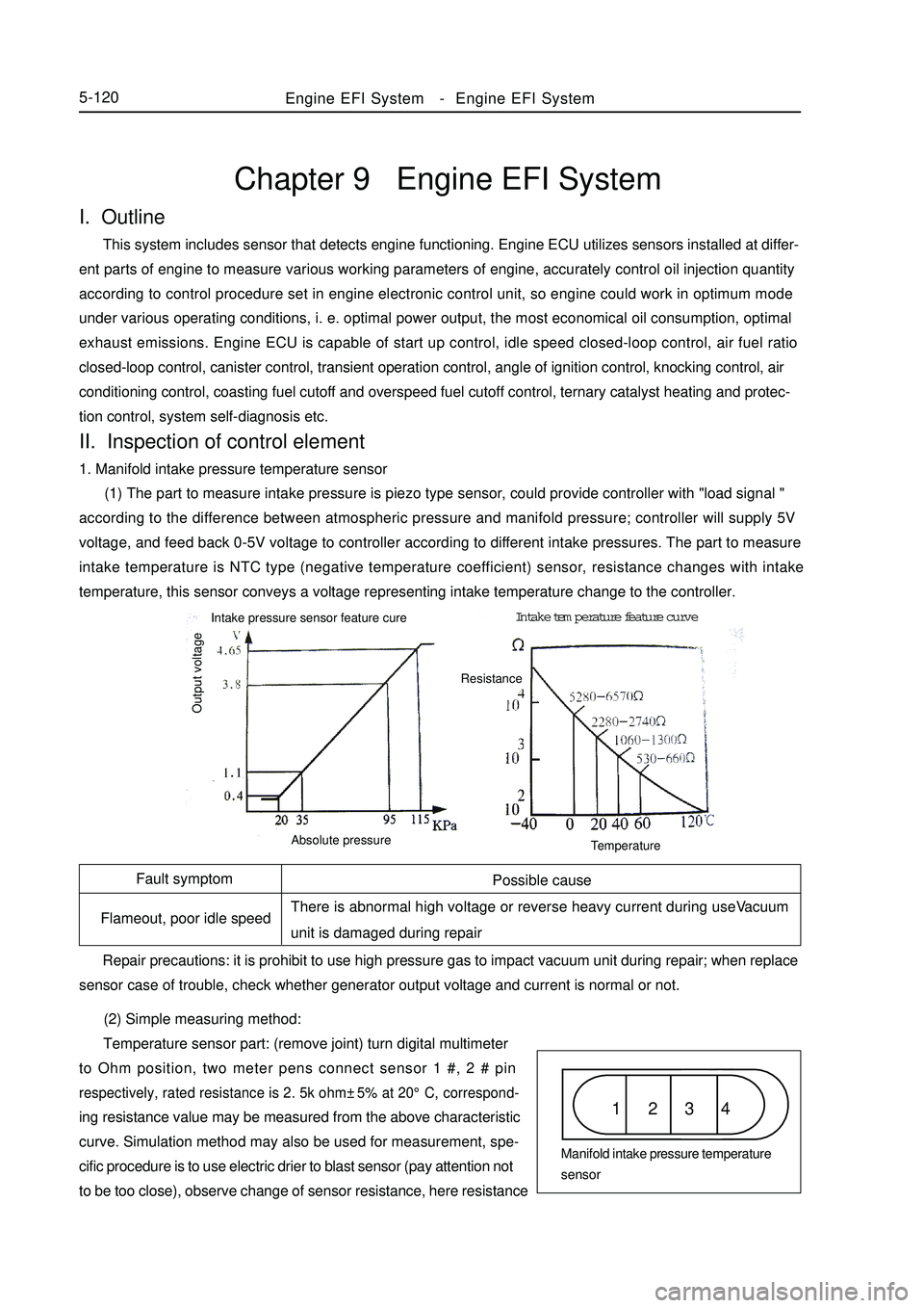
(1) The part to measure intake pressure is piezo type sensor, could provide controller with "load signal "
according to the difference between atmospheric pressure and manifold pressure; controller will supply 5V
voltage, and feed back 0-5V voltage to controller according to different intake pressures. The part to measure
intake temperature is NTC type (negative temperature coefficient) sensor, resistance changes with intake
temperature, this sensor conveys a voltage representing intake temperature change to the controller.
(2) Simple measuring method:
Temperature sensor part: (remove joint) turn digital multimeter
to Ohm position, two meter pens connect sensor 1 #, 2 # pinrespectively, rated resistance is 2. 5k ohm±5% at 20°C, correspond-ing resistance value may be measured from the above characteristic
curve. Simulation method may also be used for measurement, spe-
cific procedure is to use electric drier to blast sensor (pay attention not
to be too close), observe change of sensor resistance, here resistanceEngine EFI System-Engine EFI System5-120Possible cause
There is abnormal high voltage or reverse heavy current during useVacuum
unit is damaged during repair
Repair precautions: it is prohibit to use high pressure gas to impact vacuum unit during repair; when replace
sensor case of trouble, check whether generator output voltage and current is normal or not.1 2 3 4Manifold intake pressure temperature
sensor Intake pressure sensor feature cureIntake temperature feature curve
Output voltageAbsolute pressureTemperatureResistance
Page 308 of 416
Fault symptom Possible cause
Poor speedup etc Man made fault1 2 3Throttle position sensorFault symptom Possible cause
Difficult to start Man made fault Repair precautions: pay attention to mounting position.
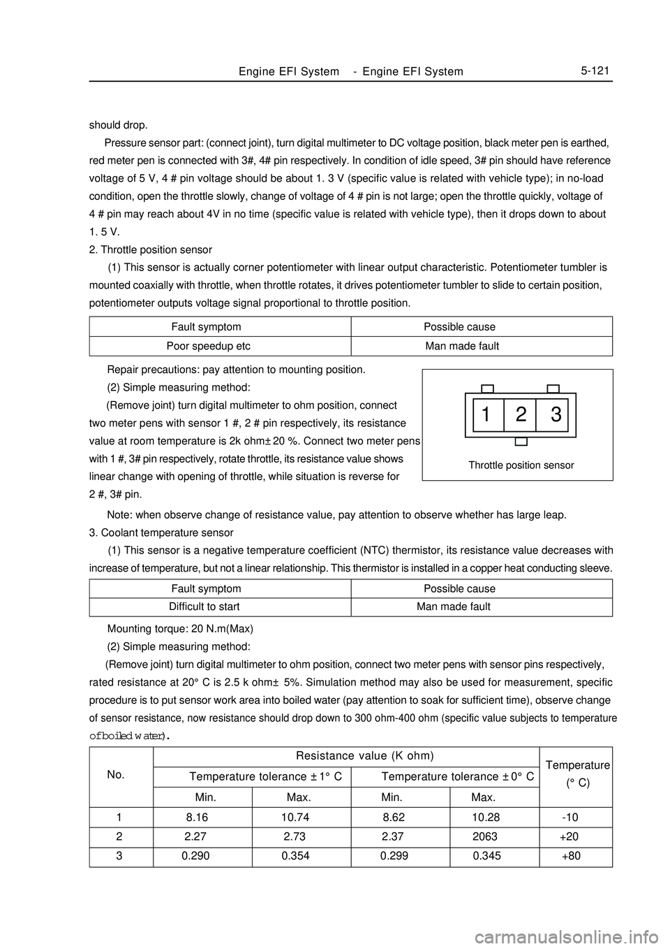
(2) Simple measuring method:
(Remove joint) turn digital multimeter to ohm position, connect
two meter pens with sensor 1 #, 2 # pin respectively, its resistance
value at room temperature is 2k ohm±20 %. Connect two meter pens
with 1 #, 3# pin respectively, rotate throttle, its resistance value shows
linear change with opening of throttle, while situation is reverse for
2 #, 3# pin.
Note: when observe change of resistance value, pay attention to observe whether has large leap.
3. Coolant temperature sensor
(1) This sensor is a negative temperature coefficient (NTC) thermistor, its resistance value decreases with
increase of temperature, but not a linear relationship. This thermistor is installed in a copper heat conducting sleeve.Engine EFI System-Engine EFI System5-121should drop.
Pressure sensor part: (connect joint), turn digital multimeter to DC voltage position, black meter pen is earthed,
red meter pen is connected with 3#, 4# pin respectively. In condition of idle speed, 3# pin should have reference
voltage of 5 V, 4 # pin voltage should be about 1. 3 V (specific value is related with vehicle type); in no-load
condition, open the throttle slowly, change of voltage of 4 # pin is not large; open the throttle quickly, voltage of
4 # pin may reach about 4V in no time (specific value is related with vehicle type), then it drops down to about
1. 5 V.
2. Throttle position sensor
(1) This sensor is actually corner potentiometer with linear output characteristic. Potentiometer tumbler is
mounted coaxially with throttle, when throttle rotates, it drives potentiometer tumbler to slide to certain position,
potentiometer outputs voltage signal proportional to throttle position. Mounting torque: 20 N.m(Max)
(2) Simple measuring method:
(Remove joint) turn digital multimeter to ohm position, connect two meter pens with sensor pins respectively,rated resistance at 20°C is 2.5 k ohm± 5%. Simulation method may also be used for measurement, specificprocedure is to put sensor work area into boiled water (pay attention to soak for sufficient time), observe changeof sensor resistance, now resistance should drop down to 300 ohm-400 ohm (specific value subjects to temperatureof boiled water).
Resistance value (K ohm)
No.Temperature
(°C) Temperature tolerance ±1°C Temperature tolerance ±0°C
Min. Max. Min. Max.
1 8.16 10.74 8.62 10.28 -10
2 2.27 2.73 2.37 2063 +20
3 0.290 0.354 0.299 0.345 +80
Page 309 of 416
4. Knocking sensor
(1) Knocking sensor is a vibration acceleration sensor. Mounted on engine cylinder body. Sensing element of
the sensor is a piezocrystal. Vibration of engine cylinder body is transferred to piezocrystal via mass block in the
sensor. Since pressure generated by vibration of mass block is applied to piezocrystal, it generates voltage on two
polar planes and turns vibration signal into voltage signal for output.5-122Symptom
Poor accelerationPossible cause
Various liquids, such as engine oil, cooling fluid, brake fluid, water etc
contact the sensor for a long time, which cause corrosion to the sensor. Mounting torque: 20 ± 5 N.M
Repair precautions: sensor must be fitted closely to cylinder body with its metal surface, any type of washer
is not permitted for installation. For wiring of sensor signal cables, note that do not let resonance occur to signal
cables, otherwise they might be broken. Energizing of high voltage between sensor 1 # and 2 # pins must be
avoided, otherwise piezoelectric element might be damaged.
(2) Simple measuring method:
(Remove joint) turn digital multimeter to ohm position, connect two meter pens with sensor 1 #, 2 # pin
respectively, its resistance value at room temperature should exceed 1M ohm. Turn digital multimeter to millivolt
position, use a hand hammer to tap near knocking sensor, now voltage signal output should be available.
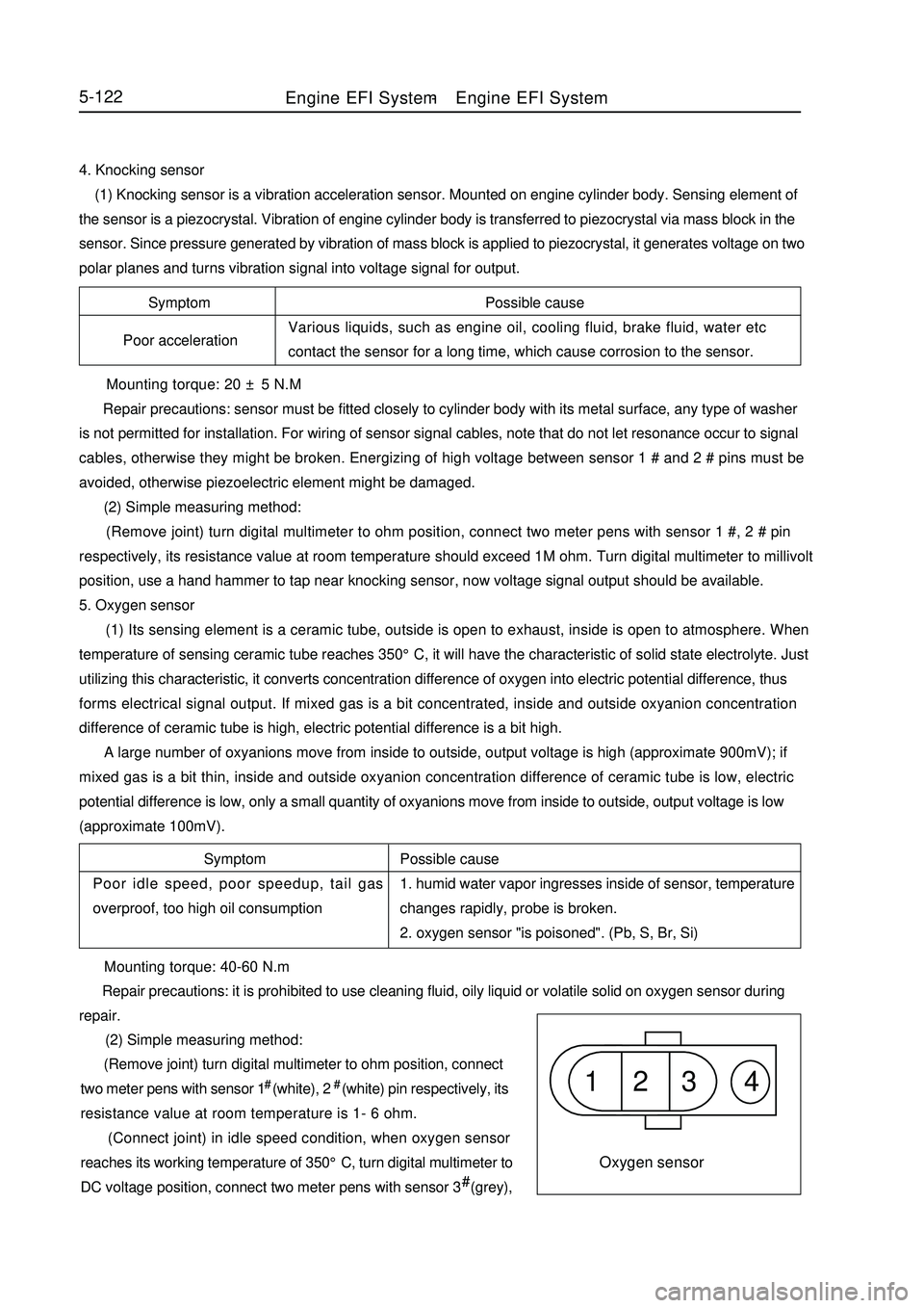
5. Oxygen sensor
(1) Its sensing element is a ceramic tube, outside is open to exhaust, inside is open to atmosphere. When
temperature of sensing ceramic tube reaches 350°C, it will have the characteristic of solid state electrolyte. Just
utilizing this characteristic, it converts concentration difference of oxygen into electric potential difference, thus
forms electrical signal output. If mixed gas is a bit concentrated, inside and outside oxyanion concentration
difference of ceramic tube is high, electric potential difference is a bit high.
A large number of oxyanions move from inside to outside, output voltage is high (approximate 900mV); if
mixed gas is a bit thin, inside and outside oxyanion concentration difference of ceramic tube is low, electric
potential difference is low, only a small quantity of oxyanions move from inside to outside, output voltage is low
(approximate 100mV).
Possible cause
1. humid water vapor ingresses inside of sensor, temperature
changes rapidly, probe is broken.
2. oxygen sensor "is poisoned". (Pb, S, Br, Si) Symptom
Poor idle speed, poor speedup, tail gas
overproof, too high oil consumption1 2 3 4Oxygen sensor Mounting torque: 40-60 N.m
Repair precautions: it is prohibited to use cleaning fluid, oily liquid or volatile solid on oxygen sensor during
repair.
(2) Simple measuring method:
(Remove joint) turn digital multimeter to ohm position, connect
two meter pens with sensor 1# (white), 2# (white) pin respectively, its
resistance value at room temperature is 1- 6 ohm.
(Connect joint) in idle speed condition, when oxygen sensor
reaches its working temperature of 350°C, turn digital multimeter to
DC voltage position, connect two meter pens with sensor 3# (grey),Engine EFI System-Engine EFI System
Page 383 of 416
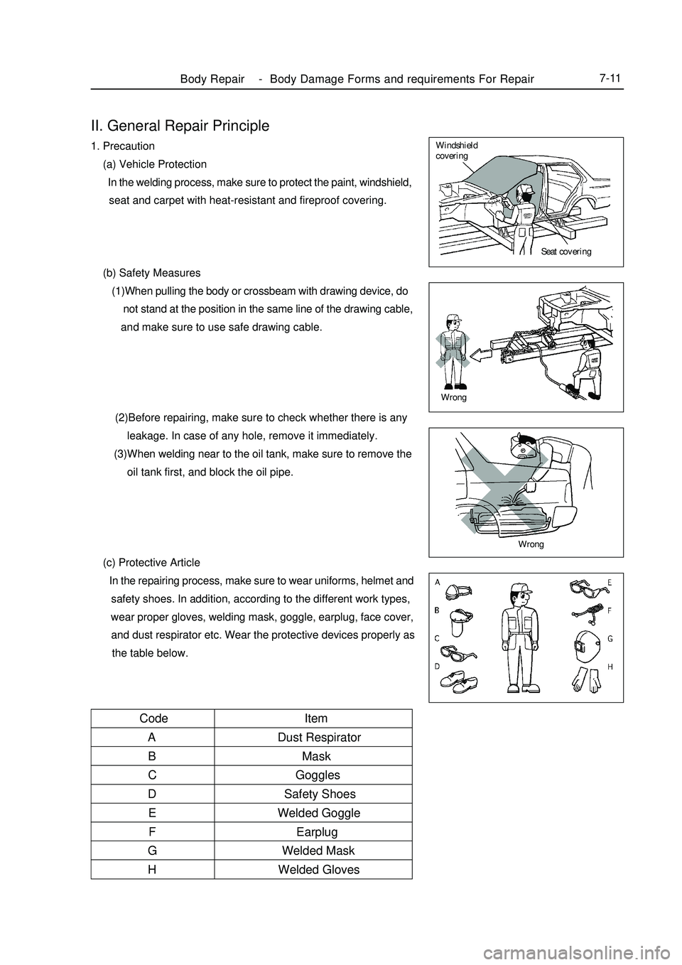
II. General Repair Principle1. Precaution
(a) Vehicle Protection
In the welding process, make sure to protect the paint, windshield,
seat and carpet with heat-resistant and fireproof covering.
(b) Safety Measures
(1)When pulling the body or crossbeam with drawing device, do
not stand at the position in the same line of the drawing cable,
and make sure to use safe drawing cable.
(2)Before repairing, make sure to check whether there is any
leakage. In case of any hole, remove it immediately.
(3)When welding near to the oil tank, make sure to remove the
oil tank first, and block the oil pipe.
(c) Protective Article
In the repairing process, make sure to wear uniforms, helmet and
safety shoes. In addition, according to the different work types,
wear proper gloves, welding mask, goggle, earplug, face cover,
and dust respirator etc. Wear the protective devices properly as
the table below.Body Repair -Body Damage Forms and requirements For Repair7-11Seat covering Windshield
coveringWrongWrongItem
Dust Respirator
Mask
Goggles
Safety Shoes
Welded Goggle
Earplug
Welded Mask
Welded Gloves Code
A
B
C
D
E
F
G
H