odometer GEELY MK 2008 Workshop Manual
[x] Cancel search | Manufacturer: GEELY, Model Year: 2008, Model line: MK, Model: GEELY MK 2008Pages: 416, PDF Size: 25.19 MB
Page 27 of 416
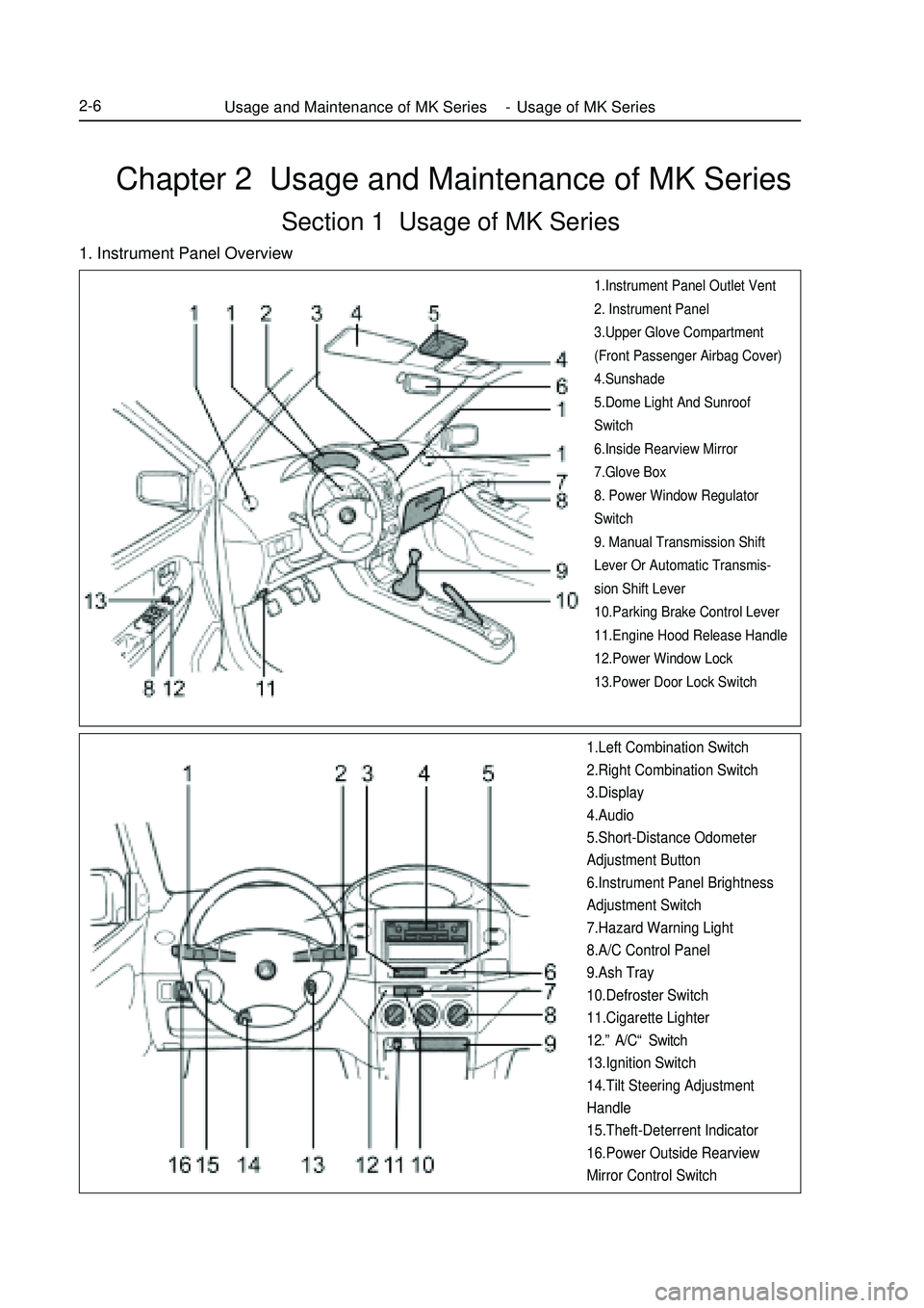
Chapter 2 Usage and Maintenance of MK SeriesSection 1 Usage of MK Series1. Instrument Panel Overview1.Instrument Panel Outlet Vent
2. Instrument Panel
3.Upper Glove Compartment
(Front Passenger Airbag Cover)
4.Sunshade
5.Dome Light And Sunroof
Switch
6.Inside Rearview Mirror
7.Glove Box
8. Power Window Regulator
Switch
9. Manual Transmission Shift
Lever Or Automatic Transmis-
sion Shift Lever
10.Parking Brake Control Lever
11.Engine Hood Release Handle
12.Power Window Lock
13.Power Door Lock Switch1.Left Combination Switch
2.Right Combination Switch
3.Display
4.Audio
5.Short-Distance Odometer
Adjustment Button
6.Instrument Panel Brightness
Adjustment Switch
7.Hazard Warning Light
8.A/C Control Panel
9.Ash Tray
10.Defroster Switch
11.Cigarette Lighter
12.”A/C“ Switch
13.Ignition Switch
14.Tilt Steering Adjustment
Handle
15.Theft-Deterrent Indicator
16.Power Outside Rearview
Mirror Control SwitchUsage and Maintenance of MK Series - Usage of MK Series2-6
Page 66 of 416
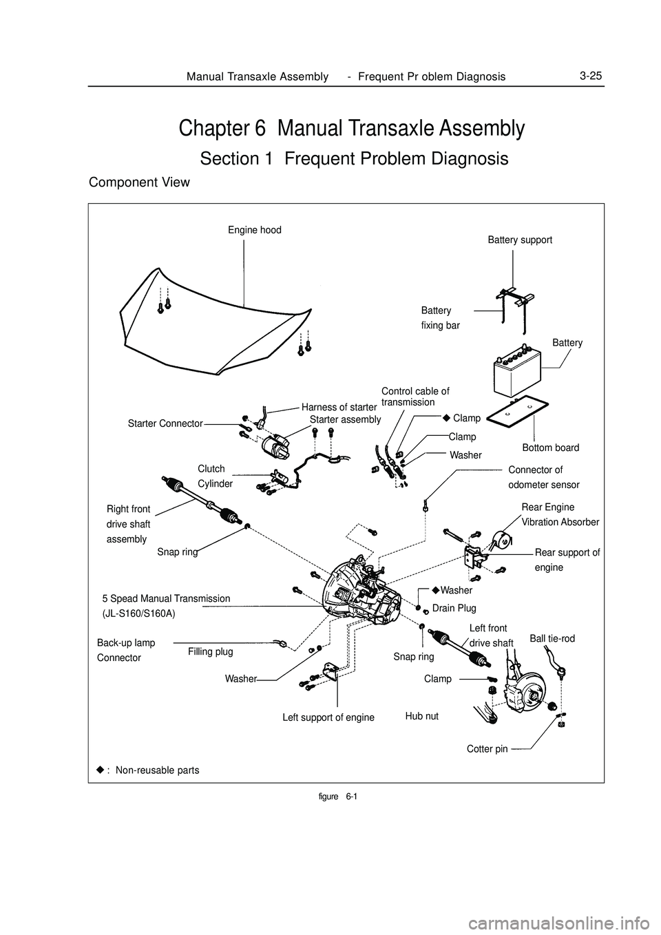
Chapter 6 Manual Transaxle AssemblySection 1 Frequent Problem DiagnosisComponent Viewfigure6-1Manual Transaxle Assembly Frequent Pr oblem Diagnosis3-25Battery support
Battery
fixing bar
Bottom board
Rear Engine
Vibration Absorber Starter assembly Engine hood
Control cable of
transmissionBattery
Harness of starter
Clamp
Clamp
Washer
Connector of
odometer sensor Clutch
Cylinder Starter Connector
Rear support of
engine
5 Spead Manual Transmission
(JL-S160/S160A)
Left front
drive shaftBall tie-rod
Cotter pin Hub nut Snap ring
Clamp
Left support of engineWasher
Washer Back-up lamp
ConnectorFilling plugDrain Plug Right front
drive shaft
assembly
Snap ring: Non-reusable parts -
Page 68 of 416
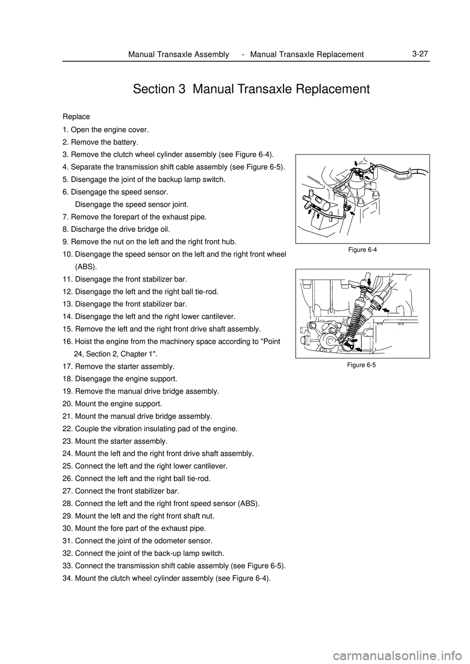
Figure 6-5Manual Transaxle Assembly Manual Transaxle Replacement3-27Section 3 Manual Transaxle ReplacementReplace1. Open the engine cover.
2. Remove the battery.
3. Remove the clutch wheel cylinder assembly (see Figure 6-4).
4. Separate the transmission shift cable assembly (see Figure 6-5).
5. Disengage the joint of the backup lamp switch.
6. Disengage the speed sensor.
Disengage the speed sensor joint.
7. Remove the forepart of the exhaust pipe.
8. Discharge the drive bridge oil.
9. Remove the nut on the left and the right front hub.
10. Disengage the speed sensor on the left and the right front wheel
(ABS).
11. Disengage the front stabilizer bar.
12. Disengage the left and the right ball tie-rod.
13. Disengage the front stabilizer bar.
14. Disengage the left and the right lower cantilever.
15. Remove the left and the right front drive shaft assembly.
16. Hoist the engine from the machinery space according to "Point
24, Section 2, Chapter 1".
17. Remove the starter assembly.
18. Disengage the engine support.
19. Remove the manual drive bridge assembly.
20. Mount the engine support.
21. Mount the manual drive bridge assembly.
22. Couple the vibration insulating pad of the engine.
23. Mount the starter assembly.
24. Mount the left and the right front drive shaft assembly.
25. Connect the left and the right lower cantilever.
26. Connect the left and the right ball tie-rod.
27. Connect the front stabilizer bar.
28. Connect the left and the right front speed sensor (ABS).
29. Mount the left and the right front shaft nut.
30. Mount the fore part of the exhaust pipe.
31. Connect the joint of the odometer sensor.
32. Connect the joint of the back-up lamp switch.
33. Connect the transmission shift cable assembly (see Figure 6-5).
34. Mount the clutch wheel cylinder assembly (see Figure 6-4).Figure 6-4 -
Page 71 of 416
The valve body fails.
12. The vehicle shifts before or after some gear points in the running status.
The vehicle switch or parking switch fails.
13. The vehicle has poor acceleration in running.
(1)The clutch or brake fails.
(2)The engine system fails.
14. The vehicle vibrates when it runs at a constant speed or accelerating speed.
(1)The hydraulic torque clutch pressure or hydraulic torque meter fails.
(2)The engine system or valve fails.
15. The acceleration switch system fails.
(1)The acceleration switch or ignition switch fails.
(2)The connector or automatic transmission control unit fails.I. Automatic transmissions Removal1. Put the select lever in "N" position
2. Remove 3 bolts of the flexibility plate (engine side)
3. Remove starter and 2 cooling hoses.
4. Disconnect neutral switch connector and odometer sensor.
5. Loosen the drain screw under the housing to bleed ATF and tighten the drain screw with sealing glue when
assembling. Tightening torque is 29~35N.m
6. Loosen the locking bolt for select lever cable.
7. Remove Drive Shaft LH&RH, using plastic stopper in the oil sealing of differential.
8. Detach suspension bolts.
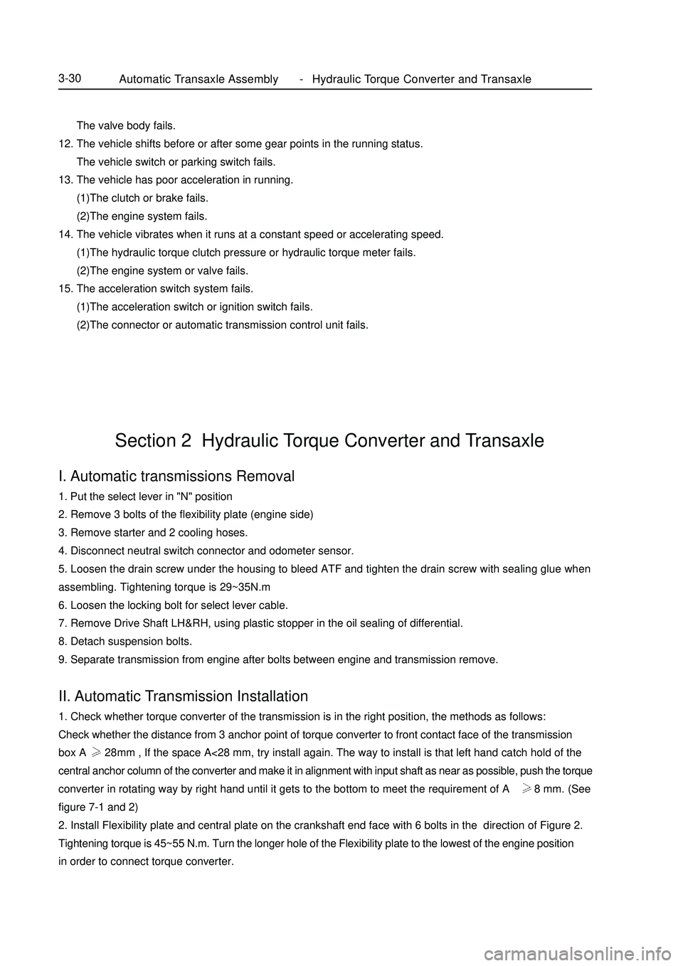
9. Separate transmission from engine after bolts between engine and transmission remove.II. Automatic Transmission Installation1. Check whether torque converter of the transmission is in the right position, the methods as follows:
Check whether the distance from 3 anchor point of torque converter to front contact face of the transmission
box A 28mm , If the space A<28 mm, try install again. The way to install is that left hand catch hold of the
central anchor column of the converter and make it in alignment with input shaft as near as possible, push the torque
converter in rotating way by right hand until it gets to the bottom to meet the requirement of A 28 mm. (See
figure 7-1 and 2)
2. Install Flexibility plate and central plate on the crankshaft end face with 6 bolts in the direction of Figure 2.
Tightening torque is 45~55 N.m. Turn the longer hole of the Flexibility plate to the lowest of the engine position
in order to connect torque converter.Section 2 Hydraulic Torque Converter and TransaxleAutomatic Transaxle Assembly Hydraulic Torque Converter and Transaxle3-30 -
Page 73 of 416
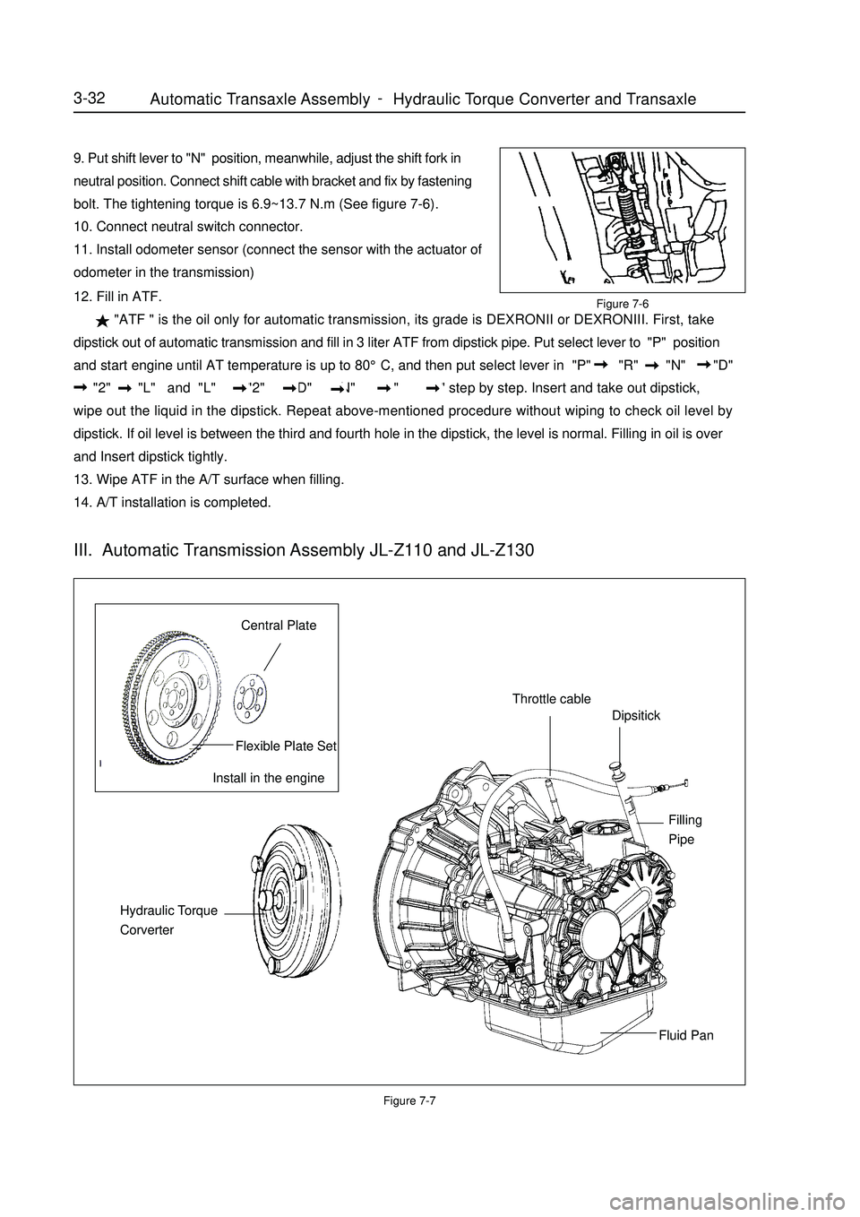
9. Put shift lever to "N" position, meanwhile, adjust the shift fork in
neutral position. Connect shift cable with bracket and fix by fastening
bolt. The tightening torque is 6.9~13.7 N.m (See figure 7-6).
10. Connect neutral switch connector.
11. Install odometer sensor (connect the sensor with the actuator of
odometer in the transmission)Figure 7-712. Fill in ATF.
"ATF " is the oil only for automatic transmission, its grade is DEXRONII or DEXRONIII. First, take
dipstick out of automatic transmission and fill in 3 liter ATF from dipstick pipe. Put select lever to "P" position
and start engine until AT temperature is up to 80°C, and then put select lever in "P" "R" "N" "D"
"2" "L" and "L" "2" "D" "N" "R" "P" step by step. Insert and take out dipstick,
wipe out the liquid in the dipstick. Repeat above-mentioned procedure without wiping to check oil level by
dipstick. If oil level is between the third and fourth hole in the dipstick, the level is normal. Filling in oil is over
and Insert dipstick tightly.
13. Wipe ATF in the A/T surface when filling.
14. A/T installation is completed.3-32Install in the engineCentral PlateFlexible Plate SetThrottle cableDipsitickFilling
PipeFluid Pan Hydraulic Torque
CorverterIII. Automatic Transmission Assembly JL-Z110 and JL-Z130Figure 7-6Automatic Transaxle Assembly Hydraulic Torque Converter and Transaxle -
Page 197 of 416
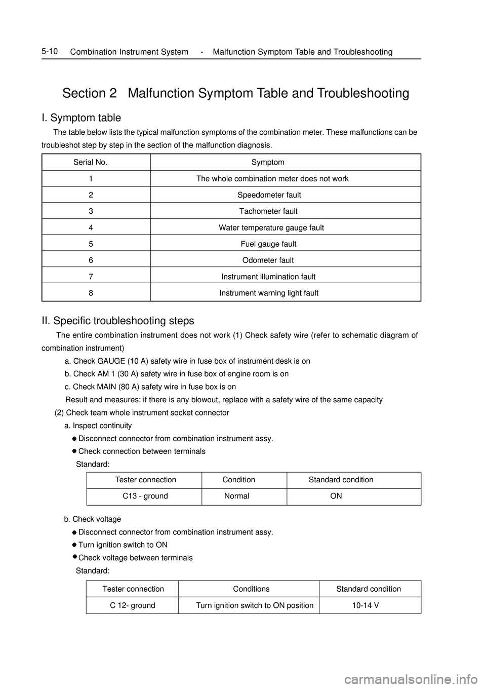
Serial No. Symptom
1 The whole combination meter does not work
2 Speedometer fault
3 Tachometer fault
4 Water temperature gauge fault
5 Fuel gauge fault
6 Odometer fault
7 Instrument illumination fault
8 Instrument warning light fault
Tester connection Condition Standard condition
C13 - ground Normal ONSection 2 Malfunction Symptom Table and TroubleshootingI. Symptom table The table below lists the typical malfunction symptoms of the combination meter. These malfunctions can be
troubleshot step by step in the section of the malfunction diagnosis.Tester connection Conditions Standard condition
C 12- ground Turn ignition switch to ON position 10-14 VCombination Instrument System -Malfunction Symptom Table and Troubleshooting5-10II. Specific troubleshooting steps The entire combination instrument does not work (1) Check safety wire (refer to schematic diagram of
combination instrument)
a. Check GAUGE (10 A) safety wire in fuse box of instrument desk is on
b. Check AM 1 (30 A) safety wire in fuse box of engine room is on
c. Check MAIN (80 A) safety wire in fuse box is on
Result and measures: if there is any blowout, replace with a safety wire of the same capacity
(2) Check team whole instrument socket connector
a. Inspect continuity
Disconnect connector from combination instrument assy.
Check connection between terminals
Standard:
b. Check voltage
Disconnect connector from combination instrument assy.
Turn ignition switch to ON
Check voltage between terminals
Standard:
Page 202 of 416
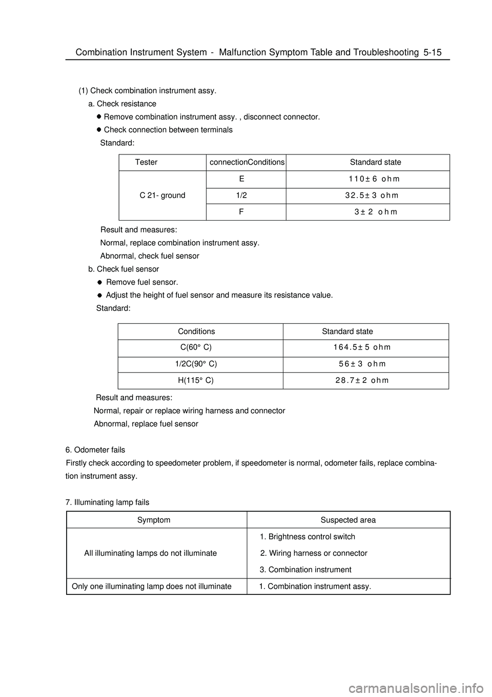
Tester connectionConditions Standard state
E 110±6 ohm
C 21- ground 1/232.5±3 ohm
F 3±2 ohmConditions Standard state5-15 (1) Check combination instrument assy.
a. Check resistance
Remove combination instrument assy. , disconnect connector.
Check connection between terminals
Standard:
Result and measures:
Normal, replace combination instrument assy.
Abnormal, check fuel sensor
b. Check fuel sensor
Remove fuel sensor.
Adjust the height of fuel sensor and measure its resistance value.
Standard:
Result and measures:
Normal, repair or replace wiring harness and connector
Abnormal, replace fuel sensor
6. Odometer fails
Firstly check according to speedometer problem, if speedometer is normal, odometer fails, replace combina-
tion instrument assy.
7. Illuminating lamp fails
Symptom
All illuminating lamps do not illuminate
Only one illuminating lamp does not illuminateSuspected area
1. Brightness control switch
2. Wiring harness or connector
3. Combination instrument
1. Combination instrument assy.Combination Instrument System -Malfunction Symptom Table and Troubleshooting C(60°C)164.5±5 ohm
1/2C(90°C)56±3 ohm
H(115°C)28.7±2 ohm
Page 205 of 416
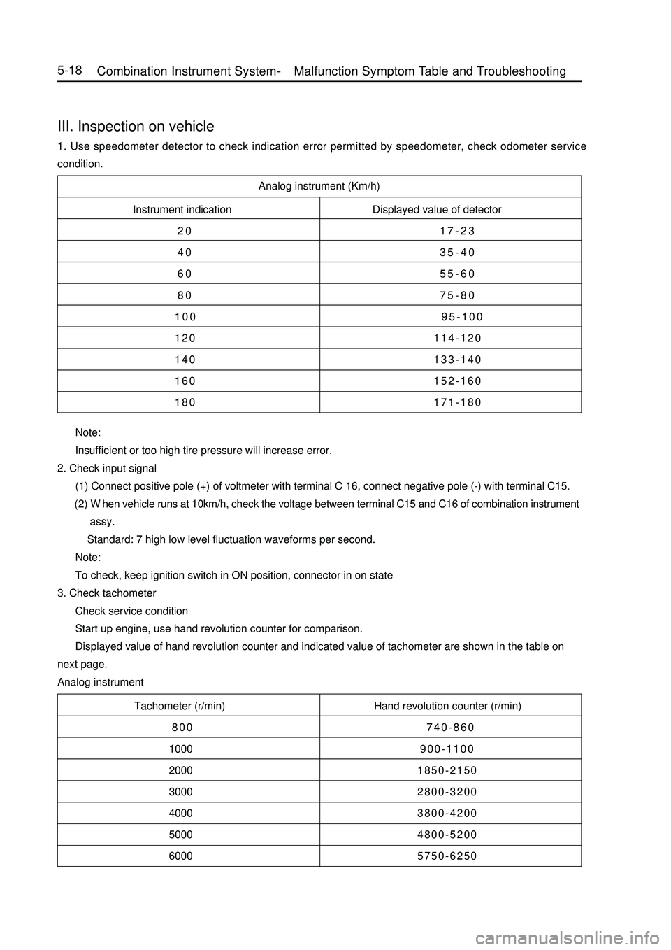
Analog instrument (Km/h)
Instrument indication Displayed value of detector
20 17-23
40 35-40
60 55-60
80 75-80
100 95-100
120 114-120
140 133-140
160 152-160
180 171-180
Tachometer (r/min) Hand revolution counter (r/min)
800 740-860
1000900-1100
20001850-2150
30002800-3200
40003800-4200
50004800-5200
60005750-6250 Note:
Insufficient or too high tire pressure will increase error.
2. Check input signal
(1) Connect positive pole (+) of voltmeter with terminal C 16, connect negative pole (-) with terminal C15.
(2) When vehicle runs at 10km/h, check the voltage between terminal C15 and C16 of combination instrument
assy.
Standard: 7 high low level fluctuation waveforms per second.
Note:
To check, keep ignition switch in ON position, connector in on state
3. Check tachometer
Check service condition
Start up engine, use hand revolution counter for comparison.
Displayed value of hand revolution counter and indicated value of tachometer are shown in the table on
next page.
Analog instrumentIII. Inspection on vehicle1. Use speedometer detector to check indication error permitted by speedometer, check odometer service
condition.5-18Combination Instrument System -Malfunction Symptom Table and Troubleshooting