trunk GEELY MK 2008 Workshop Manual
[x] Cancel search | Manufacturer: GEELY, Model Year: 2008, Model line: MK, Model: GEELY MK 2008Pages: 416, PDF Size: 25.19 MB
Page 25 of 416

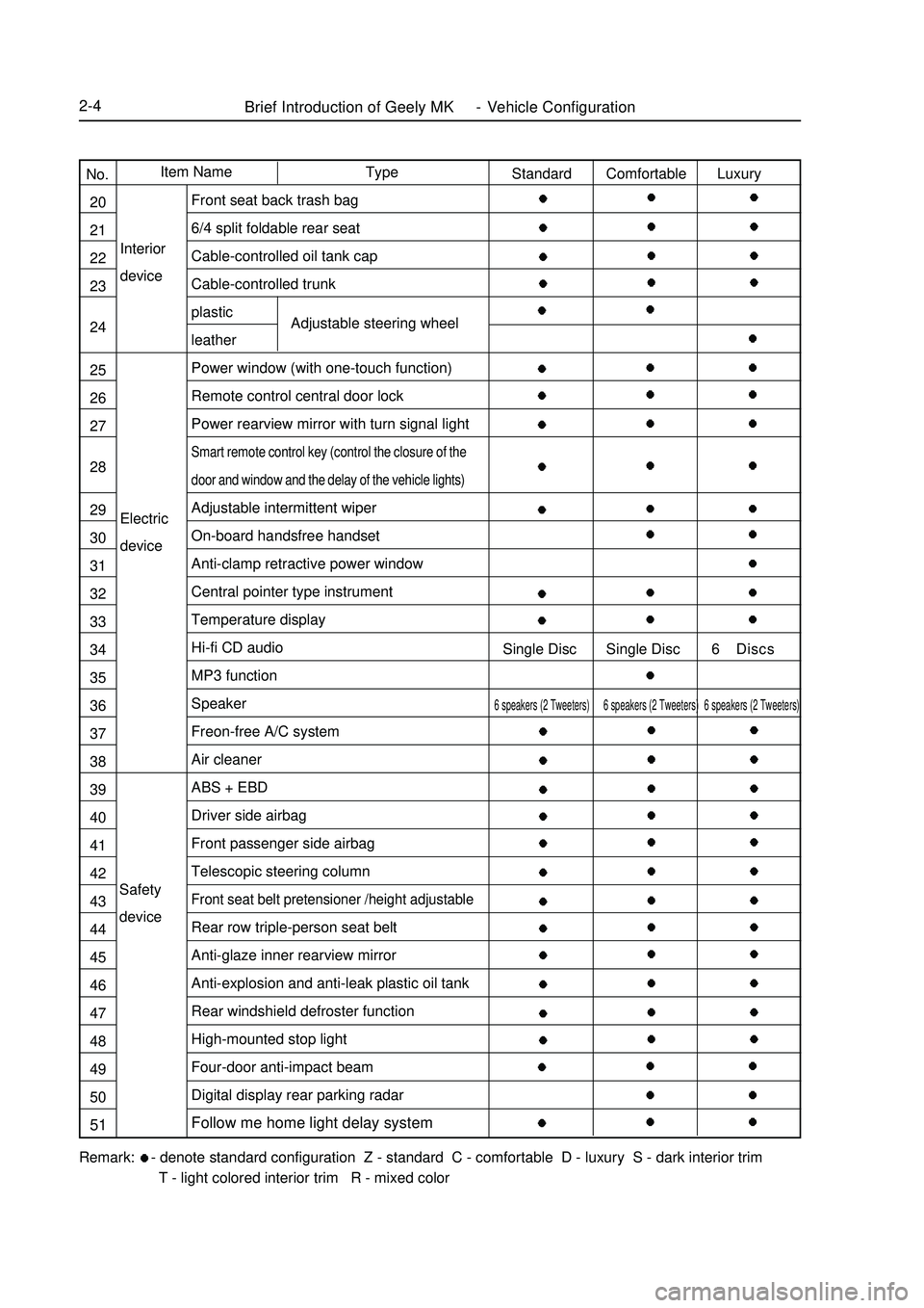
Brief Introduction of Geely MK - Vehicle Configuration2-4Electric
deviceInterior
deviceAdjustable steering wheelRemark: - denote standard configuration Z - standard C - comfortable D - luxury S - dark interior trim
T - light colored interior trim R - mixed colorType Item Name
No.
20
21
22
23
24
25
26
27
28
29
30
31
32
33
34
35
36
37
38
39
40
41
42
43
44
45
46
47
48
49
50
51Standard Comfortable Luxury
Single Disc Single Disc 6 Discs6 speakers (2 Tweeters) 6 speakers (2 Tweeters) 6 speakers (2 Tweeters)Front seat back trash bag
6/4 split foldable rear seat
Cable-controlled oil tank cap
Cable-controlled trunk
plastic
leather
Power window (with one-touch function)
Remote control central door lock
Power rearview mirror with turn signal lightSmart remote control key (control the closure of the
door and window and the delay of the vehicle lights)Adjustable intermittent wiper
On-board handsfree handset
Anti-clamp retractive power window
Central pointer type instrument
Temperature display
Hi-fi CD audio
MP3 function
Speaker
Freon-free A/C system
Air cleaner
ABS + EBD
Driver side airbag
Front passenger side airbag
Telescopic steering columnFront seat belt pretensioner /height adjustableRear row triple-person seat belt
Anti-glaze inner rearview mirror
Anti-explosion and anti-leak plastic oil tank
Rear windshield defroster function
High-mounted stop light
Four-door anti-impact beam
Digital display rear parking radar
Follow me home light delay systemSafety
device
Page 28 of 416

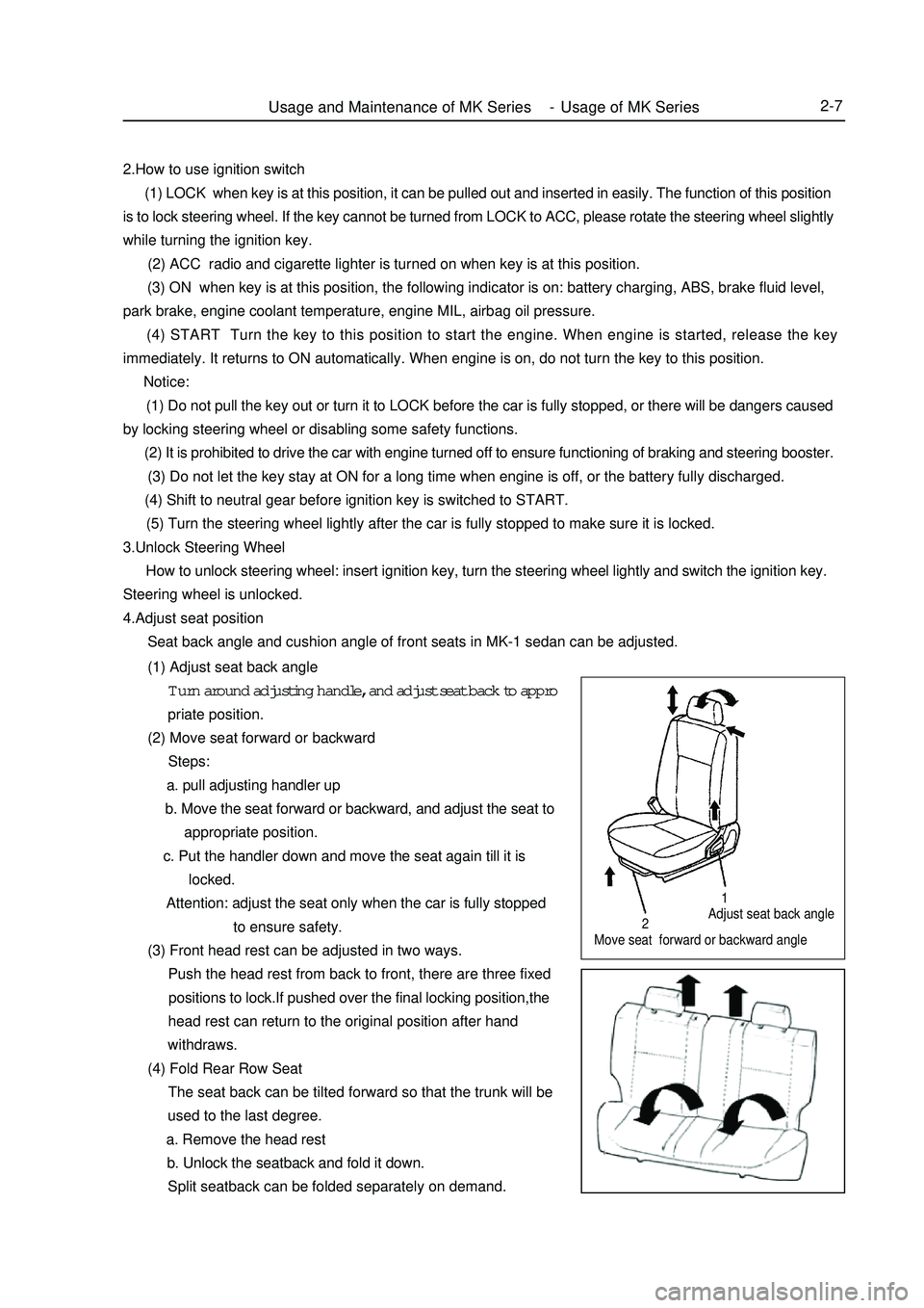
Adjust seat back angle
Move seat forward or backward angleUsage and Maintenance of MK Series - Usage of MK Series2-7212.How to use ignition switch
(1) LOCK when key is at this position, it can be pulled out and inserted in easily. The function of this position
is to lock steering wheel. If the key cannot be turned from LOCK to ACC, please rotate the steering wheel slightly
while turning the ignition key.
(2) ACC radio and cigarette lighter is turned on when key is at this position.
(3) ON when key is at this position, the following indicator is on: battery charging, ABS, brake fluid level,
park brake, engine coolant temperature, engine MIL, airbag oil pressure.
(4) START Turn the key to this position to start the engine. When engine is started, release the key
immediately. It returns to ON automatically. When engine is on, do not turn the key to this position.
Notice:
(1) Do not pull the key out or turn it to LOCK before the car is fully stopped, or there will be dangers caused
by locking steering wheel or disabling some safety functions.
(2) It is prohibited to drive the car with engine turned off to ensure functioning of braking and steering booster.
(3) Do not let the key stay at ON for a long time when engine is off, or the battery fully discharged.
(4) Shift to neutral gear before ignition key is switched to START.
(5) Turn the steering wheel lightly after the car is fully stopped to make sure it is locked.
3.Unlock Steering Wheel
How to unlock steering wheel: insert ignition key, turn the steering wheel lightly and switch the ignition key.
Steering wheel is unlocked.
4.Adjust seat position
Seat back angle and cushion angle of front seats in MK-1 sedan can be adjusted.
(1) Adjust seat back angle
Turn around adjusting handle, and adjust seat back to appro
priate position.
(2) Move seat forward or backward
Steps:
a. pull adjusting handler up
b. Move the seat forward or backward, and adjust the seat to
appropriate position.
c. Put the handler down and move the seat again till it is
locked.
Attention: adjust the seat only when the car is fully stopped
to ensure safety.
(3) Front head rest can be adjusted in two ways.
Push the head rest from back to front, there are three fixed
positions to lock.If pushed over the final locking position,the
head rest can return to the original position after hand
withdraws.
(4) Fold Rear Row Seat
The seat back can be tilted forward so that the trunk will be
used to the last degree.
a. Remove the head rest
b. Unlock the seatback and fold it down.
Split seatback can be folded separately on demand.
Page 37 of 416

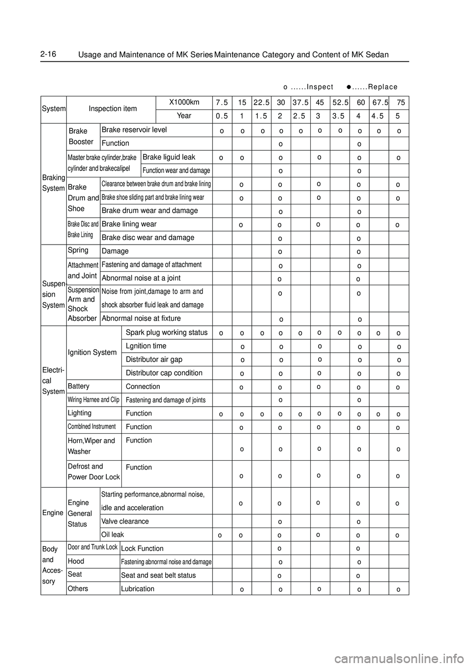
2-16......Inspect ......Replace7.5 15 22.5 30 37.5 45 52.5 60 67.5 75
0.5 1 1.5 2 2.5 3 3.5 4 4.5 5System Inspection itemX1000km
YearBraking
SystemBrake reservoir level
FunctionClearance between brake drum and brake liningBrake shoe sliding part and brake lining wearBrake drum wear and damage
Brake lining wear
Brake disc wear and damage
DamageFastening and damage of attachmentAbnormal noise at a jointNoise from joint,damage to arm and
shock absorber fluid leak and damageAbnormal noise at fixtureBrake
BoosterMaster brake cylinder,brakecylinder and brakecalipelBrake liguid leakFunction wear and damageBrake
Drum and
ShoeBrake Disc and
Brake LiningSuspen-sionSystemSpringAttachmentand JointSuspensionArm and
Shock
Absorber
Electri-
cal
SystemEngine
Body
and
Acces-
soryIgnition System
BatteryWiring Harnee and ClipLightingComblned InstrumentHorn,Wiper and
Washer
Defrost and
Power Door Lock
Engine
General
StatusDoor and Trunk LockHood
Seat
OthersStarting performance,abnormal noise,idle and acceleration
Valve clearance
Oil leakSpark plug working status
Lgnition time
Distributor air gap
Distributor cap condition
ConnectionFastening and damage of jointsFunction
Function
Function
FunctionLock FunctionFastening abnormal noise and damageSeat and seat belt status
LubricationUsage and Maintenance of MK Series - Maintenance Category and Content of MK Sedano
oo
o o o
o
o o ooo o
o o
ooo o
o o
o o
oo o
o o
oo o
o o
oo oo o
o o
o o
o o
o o
o o
o o
oo o o
o o ooo o
o o
oo o
o o
oo o
o o
oo o
o o
oo o
o o
oo o o
o o ooo o
o o
oo o
o o
oo o
o o
oo o
o o
oo o
o o
o o
ooo o
o o
oo oo oo oo o
Page 213 of 416

Chapter 4 Light SystemSection 1 Light System IntroductionI. Composition Light system comprises external illumination and signal system and internal illumination system.
The function of the external illumination and signal system is to illuminate the road ahead and send signals
to other vehicles.
The internal illumination system provides internal illumination for driver and passengers.II. Precaution for service1. Precaution when repairing electrical equipments
Disconnect the battery ground cable.
2. Precaution when replacing a headlamp bulb
(1) Before replacing a halogen bulb, turn the headlamp OFF to make it cool.
(2) When installing a new halogen bulb, do not touch the glass part of the bulb with bare hands.
(3) If there is oil stain on the surface of halogen bulb (headlamp and front fog lamp) when the lamps are
turned ON, its service life will be shortened.
(4) Halogen bulbs (headlamp and front fog lamp) have pressurized gas inside and require special handling.
They can explode if dropped to ground. The glass fragments will splash up.
(5) When replacing, make sure to use the bulbs with the same power, same model.
(6) After the bulb is installed, make the lamp holder tight.III. Bulb specificationsRemark: All bulbs are made by Philips Corp..Light System-
Light System Introduction5-26Name Specifications
Headlamp (High beam and Low beam) H1 12V 55W
Turn signal lamp PY21W 12V 21W
Position lamp W5W 12V 5W
Front fog lamp H3 12V 55W
Rear combination lamp (Turn signal lamp) PY21W 12V 21W
Rear combination lamp (Brake / Position lamp) P21/5W 12V 21/5W
Rear combination lamp (Rear fog lamp) P21W 12V 21W
Rear combination lamp (Back-up lamp) P21W 12V 21W
Interior lamp (dome lamp) R5W 12V 5W
Rear row reading lamp C5W 12V 5W
Side turn signal lamp W5W 12V 5W
High mounted stop lamp (incl. rear trunk lamp) W5W 12V 5W
License plate lamp W5W 12V 5W
Door courtesy lamp W5W 12V 5W
Page 217 of 416

Fault symptom
License light does not illuminate (taillight is
normal)Possible parts
1. Bulb
2. Wire harnessFault symptom
Trunk lamp does not illuminate (room lamp is
normal)Possible parts
1. Bulb
2. Trunk lamp switch
3. Wire harness Symptom
Back-up lamps on both sides do not light up
Back-up lamps on both sides remains always ON
Back-up lamp dose not light (One side)Suspected Area
1. Back-up lamp fuse
2. Back-up lamp switch assembly
3. Harness
1. Back-up lamp switch assembly
2. Harness
1. Bulb
2. Harness
Symptom
Interior lamp dose not light (All)
Room lamp dose not light up Rear row reading
lamp assembly is normal
One door is ajar, room lamp dose not light up on
DOOR, (It is normal on ON)
Central LH/RH room lamps do not light up
Rear row reading lamp is abnormal (Room lamp
assembly is normal)Suspected Area
1. ROOM Fuse
2. Harness
1. Bulb
2. Room lamp assembly
3. Harness
1. Door courtesy lamp switch
2. Central controller
3. Harness
1. Bulb
2. Switch
1. Bulb
2. Rear row reading lamp assembly
3. Harness 6. Back-up lamp system
7. Interior light system8. License light
9. Trunk lampLight System -Light System Malfunction Inspection5-30
Page 220 of 416

4. Danger alarm lamp switch assembly
Check whether danger alarm lamp switch is connected.
Check whether two terminals are connected when switch works.
If it doest not meet stipulation, replace the switch.
5. Door lamp switch (on fastener)
Check whether door lamp switch is connected
When switch works, check whether connection is established
between terminal and bodywork earthing.
If it doest not meet stipulation, replace the switch.
6. Trunk lamp switch assembly
Check whether trunk lamp switch is connected
When switch works, check whether connection is established between terminal and bodywork earthing.
If it doest not meet stipulation, replace the switch.
7. Front reading light assembly (with power sunroof)
Check whether terminals of indoor roof lamp assembly are
connectedSwitch motion Testing terminal Status
ON 1-2 ON
OFF 1-2 OFFSwitch motion Testing terminal Status
ON (door is closed) 1- GND ON
OFF (door is not closed) 1- GND OFF
Switch motion Testing terminal Status
ON 1- GND ON
OFF 1- GND OFFSwitch motion Testing terminal Status
ON 1-2 ON
OFF 1-2 OFF If it does not meet stipulation, replace roof lamp or switch.
8. Rear reading light assembly
Check whether back row reading light assembly is connected
When switch works, check whether two terminals are connectedSwitch motion Testing terminal Status
ON 1- 2 ON
OFF 1- 2 OFF If it doest not meet stipulation, replace the switch.211Light System -Light System Malfunction Inspection5-33
Page 223 of 416

Section 6 High-mounted Stop light ReplacementDisconnect the connector.
Remove the High mounted stop lamp in direction 1 and 2. (as shown
above in the illustration)I. Removal1. Remove trunk weather strip and trim.
2. Remove 3 installation nuts (as shown in the figure).
3. Remove rear combination light electrical connector.
4. Pull out rear combination light assembly towards vehicle backside.II. Installation1. Mount rear combination light, mount 3 installation nuts.
2. Mount electrical connector.
3. Mount trunk trim.
4. Mount weatherstrip.III. Replacement of rear combination light bulb1. Take off seal ring
2. Turn lamp holder anticlockwise, take off lamp holder
3. Take off bulb, replace bulbSection 5 Rear Combination Lamp ReplacementRear
shelf
High-mount stoplightlamp
holderLight System -Rear Combination Lamp Replacement/High-mounted Stop light Replacement5-36
Page 240 of 416

Audio System -Audio System Replacement5-53V. Rear loudspeaker assembly1. Remove rear loudspeaker shelf
2. Remove rear loudspeaker assembly
a. Disconnect connector
b. Remove three tapping screws and loudspeaker assemblyVI. Remove antenna conductor (Retractable antenna)1. Remove vehicle ceiling internal decorations
2. Remove A column decorative board
3. Disconnect connector
4. Remove instrument desk
5. Remove wire clip and antenna conductorVII. Multi-disc Exchanger1. Remove left trunk internal decorations
2. Disconnect connector
3. Remove four bolts and exvhanger
Page 350 of 416

Interior & Exterior Trim and Accessory -Rear Window Glass (with Defrosting Heater Wire)6-211. Remove the assembly of rear seatback; (Refer to "Removal and Installation of Seat")
2. Remove the interior decorative components of vehicle top; (Refer to "Removal and Installation of Interior
Decorative Components of Vehicle Top" )
3.Remove the upper decorative plate at the right-rear enclosure;
(Refer to "Removal and Installation of Interior Decorative Com-
ponents at side enclosure" )
4.Remove the assembly of high-level brake light;
(Refer to "Removal and Installation of Interior Decorative Com-
ponents at side enclosure" )
5. Remove the assembly of trunk shelf;
(Refer to "Removal and Installation of Interior Decorative Com-
ponents at side enclosure" )
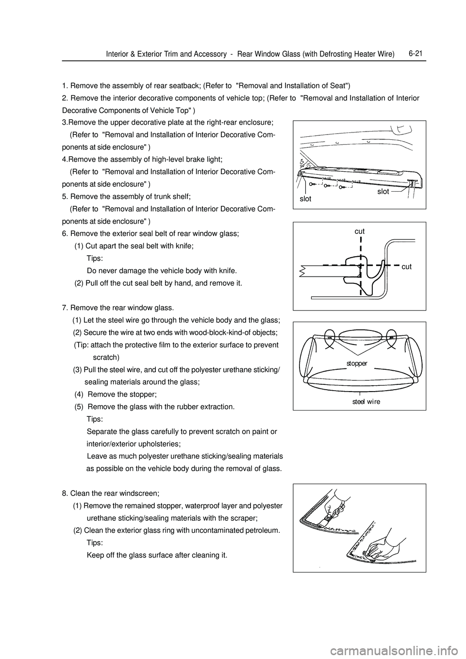
6. Remove the exterior seal belt of rear window glass;
(1) Cut apart the seal belt with knife;
Tips:
Do never damage the vehicle body with knife.
(2) Pull off the cut seal belt by hand, and remove it.
7. Remove the rear window glass.
(1) Let the steel wire go through the vehicle body and the glass;
(2) Secure the wire at two ends with wood-block-kind-of objects;
(Tip: attach the protective film to the exterior surface to prevent
scratch)
(3) Pull the steel wire, and cut off the polyester urethane sticking/
sealing materials around the glass;
(4) Remove the stopper;
(5) Remove the glass with the rubber extraction.
Tips:
Separate the glass carefully to prevent scratch on paint or
interior/exterior upholsteries;
Leave as much polyester urethane sticking/sealing materials
as possible on the vehicle body during the removal of glass.
8. Clean the rear windscreen;
(1) Remove the remained stopper, waterproof layer and polyester
urethane sticking/sealing materials with the scraper;
(2) Clean the exterior glass ring with uncontaminated petroleum.
Tips:
Keep off the glass surface after cleaning it.slotslot
cut
cut
stopper
steel wire
Page 364 of 416

Chapter 13 Rear BumperI. Component ViewRight trunk trim board
Rear shelf lower trim panel
Spare tire board
Rear bumper support installation nut
Torque nut: 6 N¡¤mRear bumper Left mud guard Left trunk trim boardInterior & Exterior Trim and Accessory -Rear Bumper6-35II. Disassembly and assembly of the rear bumper Notes:
Installation is basically the reverse of removal and different operation(s) in the process of installation, if any,
will be pointed out specifically.
1. Remove the spare tire cover assembly.
2. Remove the lower trim board of the rear separator.
3. Remove the ornamental blanket at the left side of the luggage compartment.
a. Remove six snaps.