turn signal GEELY MK 2008 Workshop Manual
[x] Cancel search | Manufacturer: GEELY, Model Year: 2008, Model line: MK, Model: GEELY MK 2008Pages: 416, PDF Size: 25.19 MB
Page 25 of 416
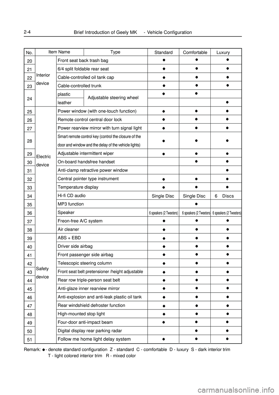
Brief Introduction of Geely MK - Vehicle Configuration2-4Electric
deviceInterior
deviceAdjustable steering wheelRemark: - denote standard configuration Z - standard C - comfortable D - luxury S - dark interior trim
T - light colored interior trim R - mixed colorType Item Name
No.
20
21
22
23
24
25
26
27
28
29
30
31
32
33
34
35
36
37
38
39
40
41
42
43
44
45
46
47
48
49
50
51Standard Comfortable Luxury
Single Disc Single Disc 6 Discs6 speakers (2 Tweeters) 6 speakers (2 Tweeters) 6 speakers (2 Tweeters)Front seat back trash bag
6/4 split foldable rear seat
Cable-controlled oil tank cap
Cable-controlled trunk
plastic
leather
Power window (with one-touch function)
Remote control central door lock
Power rearview mirror with turn signal lightSmart remote control key (control the closure of the
door and window and the delay of the vehicle lights)Adjustable intermittent wiper
On-board handsfree handset
Anti-clamp retractive power window
Central pointer type instrument
Temperature display
Hi-fi CD audio
MP3 function
Speaker
Freon-free A/C system
Air cleaner
ABS + EBD
Driver side airbag
Front passenger side airbag
Telescopic steering columnFront seat belt pretensioner /height adjustableRear row triple-person seat belt
Anti-glaze inner rearview mirror
Anti-explosion and anti-leak plastic oil tank
Rear windshield defroster function
High-mounted stop light
Four-door anti-impact beam
Digital display rear parking radar
Follow me home light delay systemSafety
device
Page 29 of 416
2-85. Actions to ensure vehicle working condition and safe driving.
(1) To make sure of driving safety, execute the following inspections before driving.
a. Inspect fuel level, and add fuel when necessary.
b. Inspect illuminating lights, turning signal lights, braking signal lights to see if they work.
c.Check the position of rearview mirrors.
d.Check if breaking system functions well.
e.Check if glass of all the lights, windshield is clean.
(2) Regular inspection Perform the following regular inspections to ensure the vehicle work condition and
driving safety.
a. Check engine oil level. Park the vehicle on flat road; check the oil level with engine oil level indicator
at least 10 minutes after the engine is stopped. The oil level should be between the two marks. If it is
lower than "L" mark, add some oil; if it is higher than "F" mark, there is excessive oil, so release it.
Or investigate the cause of high oil level.
The volume between the lowest oil level ("L") and highest oil level ("F") is 1.4L.
b. Check engine coolant level. Check the level when the engine is cool. The coolant level should be between
LOW and FULL. If it is lower than "LOW", add coolant. If the coolant is much lower than Min (every
coolant fill is more than 1L) or the vehicle requires frequent fills,investigate if there is any problem with
the cooling system.
To keep the function of coolant, replace coolant every two years at the beginning of cold winter.
c. Check brake and clutch fluid level (sharing a reservoir). Brake fluid level should between the Max and
Min marks. And it is better to keep it close to the Max mark. Add fluid in time when there is not enough
fluid.
d. Check power steering fluid tank. The level should be between Max and Min marks. Refill when there
is not enough steering fluid to avoid pump stuck. It is strictly prohibited to run the vehicle without
steering fluid in any circumstances.
e. Check the charging status of battery and if the connection of battery wires is good.
f. Check tire status and pressure
g. Check the status of wipers.
(3) Observe warning lights and indicators on instrument panel.
a. There are various warning lights and indicators on the instrument panel of MK-1 sedans to indicate and
warn abnormal operations of engine, braking, and charging systems.
b. Pay attention to these lights when driving.When the warning lights or indicators are on,stop the vehicle,
check the vehicle and resolve the causes to make sure the vehicle works well or drives safely.
6. Correct ways to use new cars
Reliability and stability of components in new cars and recently repaired cars still need to be confirmed, and
relative parts are not broken-in, so they must be used carefully to ensure driving safety, to avoid abnormal damage,
and to extend the useful life of the car.
(1) Before driving inspection The following inspections must be performed on the new car to ensure car safety
and reliable operation:
a. Check if instrument panel, warning lights, and indicator, front and rear wiper and washer, and switches
work.
b. Check if the fastening of driveline, steering, suspension, wheels and other connection parts is good.Usage and Maintenance of MK Series - Usage of MK Series
Page 30 of 416
2-9 c. Check levels of braking fluid, engine coolant, engine oil, transmission oil, power steering fluid, and
washing fluid to see if there is any leaking.
d. Inspect if brake pedal, clutch pedal, accelerator pedal, transmission shifter, steering wheel, choke are
loose or stuck. The free travel of clutch pedal is 5~15mm, the free travel of brake pedal is 1~6mm and
the free play of steering wheel is less than 30mm(measurement point at margin of steering wheel). if it
is out of this normal range, the clutch needs to be tuned.
e. Inspect if the connection of battery, lamps and signal lights are normal, and if the wire routing and
position are correct and not loose.
f. Inspect if the tire pressure is correct.
(2) On-road inspection If the inspection result of the above items is good, start the engine and test the car on
road, and perform the following inspections.
a. Acceleration pedal, see if the operation is smooth and if it is loose.
b. Clutch, see if there is any stuck or abnormal noise, and slip when driving.
c. Transmission,check if shifting is smooth,or rough and wrong shifting.Inspect if the display of A/T
shift lever is normal.
d. Steering, check if steering is light and smooth, and if the steering wheel turns back after steering.
e. Brake pedal, apply brake pedal to check if the braking functions well when vehicle speed is at
40km/h and if the vehicle runs off track.
f. Park brake, when parking brake handler is pulled, there should be 6~9 clicking sounds. Pull park brake
when vehicle is running at the speed of 20km/h and transmission is at neutral gear to see if it brakes.
g. Vehicle speed meter, observe the vehicle speed meter while driving. When speed changes, check if the
indicator is moving steadily or shakes.
h. Heating and air-conditioning.Try every control button to see if both heating and cooling system work
well.
i. Abnormal noise, listen carefully to see if there is any abnormal noise from engine, drive line system or
any other parts of the vehicle at a steady speed and during accelerating, and decelerating.
(3) Inspection after test ride check if there is anything abnormal in the vehicle while driving and conduct the
following inspections after the vehicle is parked.
a. Check electrical fan When engine coolant temperature is beyond 92.5°C, the radiator fan should be
running; When A/C is on and the pressure of refrigerant is more than 1.5 cooling ton, air conditioning
cooling fan should be running.
b. Check headlamp, method: park the car 5m away from the inspection surface (inspection board, curtain,
or wall) to the front bumper, and check if the beam from headlamp is good. The upper level if headlamp
should be 540mm above the ground, and the distance between headlamps on the two sides is 900mm.
c. Inspect engine idle speed,idle speed of hot engine is 800r/min±50r/min,when A/C compressor works,
the idle speed should be 900r/min±50r/min. If idle speed is abnormal, adjust the idle speed adjust
ment screw to adjust it.
(4) Usage of new cars in breaking-in period Follow the instructions below in the first 1500~2500km breaking
mileage to avoid wear and abnormal damage in breaking-in period, and to improve vehicle performance, fuel
economy and to extend vehicle useful life.
a. Drive steadily during breaking-in; do not accelerate harshly to avoid running engine at high speed.
Engine should not exceed 4500r/min in any gears. Especially at the early stage of breaking-in, vehicleUsage and Maintenance of MK Series - Usage of MK Series
Page 31 of 416
2-10 must be running at medium speed without load. Increase the speed and load gradually with the
accumulation of breaking-in mileage.
b. Because the brake plat is not broken in on a new vehicle,in order to ensure safety and reduce wear,avoid
harsh brake, and brake for multiple times to break in the brake plate faster.
c. It is better to avoid driving vehicle on steep roads or in bad conditions during breaking-in period.
d. Pay special attention to engine coolant temperature meter and oil pressure meter.Check engine oil level
frequently and make sure engine works in normal temperature and good lubrication.
e. Maintain the vehicle strictly according to first-time maintenance requirements to bring the vehicle into
normal usage life under good condition.
7.vehicle towing
There are towing facilities both in the front and rear end of MK-1 sedan for towing other vehicles and being towed.
To ensure safety, pay attention to the following instructions when towing.
(1) Towing car Towing car should be started and shifted steadily.The speed should be no more than 40km/h.
(2) Follow the instructions below when being towed:
a. Steering system of the vehicle being towed works well.
b. Braking system of the vehicle being towed works well or it cannot be towed with a rope and must be
towed with the towing shaft instead.
c. Release park brake and shift the transmission to neutral gear when the vehicle is being towed.
d. Turn the ignition switch to ACC to allow turning signal lights,braking indicator to be turned on when
necessary.
e. The towing rope must be tensioned in the towing process.
f. If the purpose of towing is to start the engine, shift the transmission to the 2nd or 3rd gear to increase
engine speed. It is good for starting the engine.
8. Instructions to save fuel when using the vehicle
(1) Reasonable load Do not store useless articles in luggage compartment because they consumes fuel for
nothing.
(2) Correct driving style Instructions as follows:
a. When engine is started, do not heat it but press the accelerator pedal slightly, drive the vehicle slowly
and accelerate gradually.
b. Shift to higher gears when driving to allow the engine to work at appropriate engine speed and avoid
running the engine at low or high speed. The engine speed should be higher than 2500r/min when
driving, and higher than 3000r/min when up-shifting.
c. Keep the vehicle speed stable, and avoid harsh acceleration and frequent braking.
d. Pay attention to vehicle speed. Drive at high speed results in excessive fuel consumption.
(3) Organize vehicle usage well Pay attention to the following two instructions.
a. Organize vehicle usage time and avoid short trips. Because at the beginning when the vehicle is started
(around 1km), the engine has not reached its efficiency point, and the fuel consumption doubles
compared to regular.
b. Select a good driving route, avoid driving through the city or blocks with heavy traffic.
(4) Keep the vehicle under good work condition Strictly follow instructions to maintain the vehicle to make
sure the vehicle is under good technical working condition, and inspect and replace key parts that affect vehicle
fuel consumptions. For example:Usage and Maintenance of MK Series - Usage of MK Series
Page 196 of 416
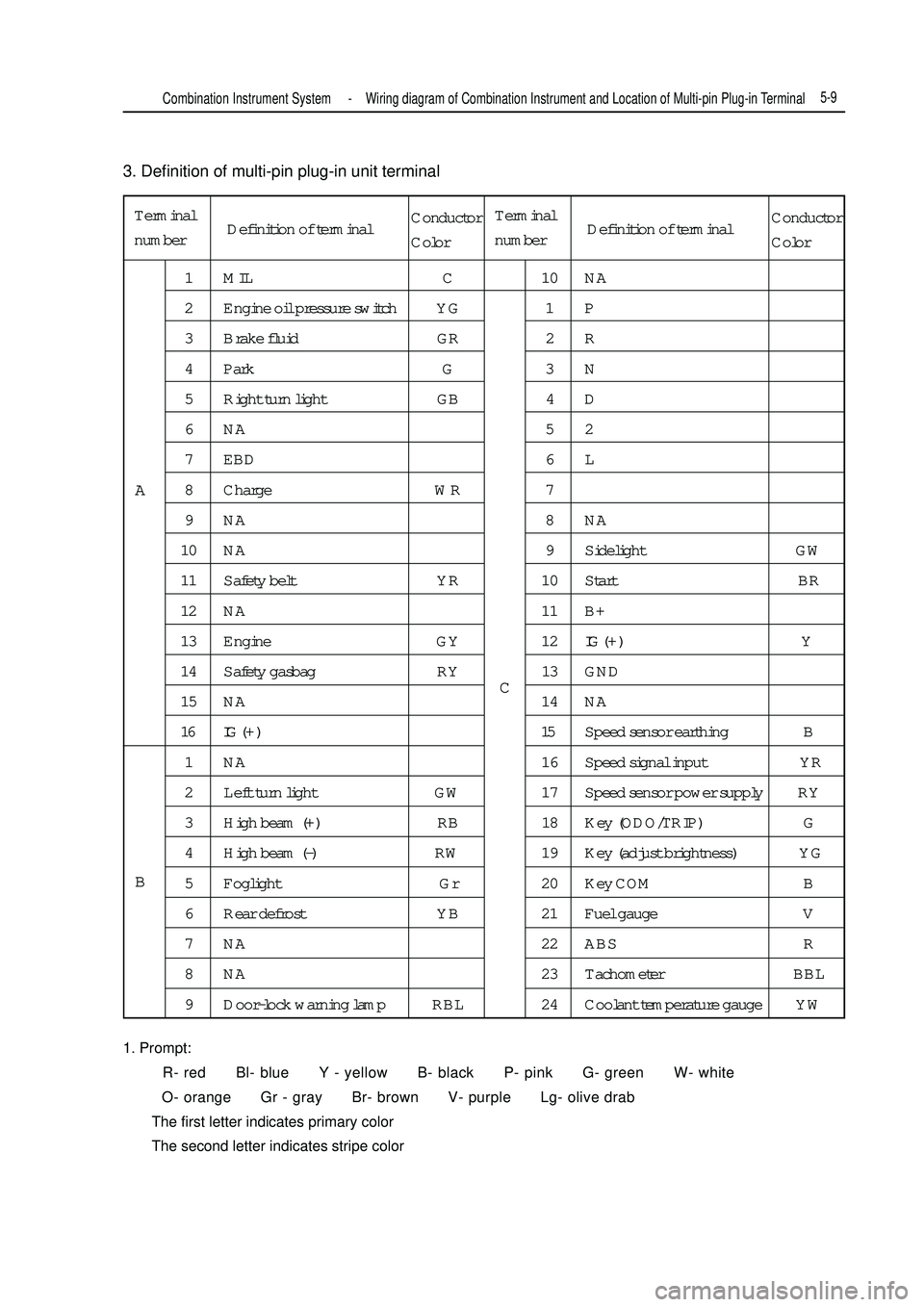
3. Definition of multi-pin plug-in unit terminal
1. Prompt:
R- red Bl- blue Y - yellow B- black P- pink G- green W- white
O- orange Gr - gray Br- brown V- purple Lg- olive drab
The first letter indicates primary color
The second letter indicates stripe colorTerminal
number1 MIL C 10 NA
2 Engine oil pressure switch YG 1 P
3 Brake fluid GR 2 R
4 Park G 3 N
5 Right turn light GB 4 D
6NA 52
7 EBD 6 L
8 Charge WR 7
9NA 8NA
10 NA 9 Sidelight GW
11 Safety belt YR 10 Start BR
12 NA 11 B+
13 Engine GY 12IG ( + ) Y
14 Safety gasbag RY 13 GND
15 NA 14 NA
16 IG ( + ) 15Speed sensor earthing B
1 NA 16 Speed signal input YR
2 Left turn light GW 17 Speed sensor power supply RY
3 High beam (+) RB 18 Key (ODO/TRIP) G
4 High beam (-) RW 19 Key (adjust brightness) YG
5 Foglight Gr 20 Key COM B
6 Rear defrost YB 21 Fuel gauge V
7 NA 22 ABS R
8 NA 23 Tachometer BBL
9 Door-lock warning lamp RBL 24 Coolant temperature gauge YWA
BCCombination Instrument System -Wiring diagram of Combination Instrument and Location of Multi-pin Plug-in Terminal5-9Definition of terminalConductor
ColorTerminal
numberDefinition of terminalConductor
Color
Page 198 of 416

c.Check voltage between terminals
Standard:Rotating wheel 7.5-9V
Below 0.5V0Voltage changes alternativelyCombination Instrument System -Malfunction Symptom Table and Troubleshooting5-11 Result and measures:
Normal, replace combination instrument assy.
Abnormal, repair or replace wiring harness or connector
2. Speedometer fails
Check
(1) Check combination instrument assy.
a. Remove combination instrument assy. , keep connection of connector.
b. Check on state
Check connection between terminals
Standard:Tester connection Conditions Standard condition
C 17- ground Turn ignition switch to ON position 7. 5-9V
Result and measures:
Abnormal, go to (2) Check combination instrument assy. speed input signal
Normal, go to (3) Check combination instrument assy.
(2) Check combination instrument assy. speed input signal
a. Check voltage
Prop up two front wheels
Push transmission lever to neutral position
Turn on ignition switch
turn front wheel slowly, measure the voltage between terminal C15 and terminal C16
Standard voltage is shown in the figure below:
Result and measures:
Normal, replace combination instrument assy.
Abnormal, check speed sensorTester connection Condition Standard condition
C 15-ground Normal ON
Page 199 of 416

Check voltage between terminals
Standard:7.5-9V
0Voltage changes alternatively5-12 b. Check speed sensor
Check on state
Check connection between terminals
Standard:Tester connection Conditions Standard condition
3- ground Turn ignition switch to ON position 7. 5-9VTester connection Condition Standard condition
2- ground Normal ON Result and measures:
Abnormal, repair or replace wiring harness or connector
Normal, check speed sensor output signal
c. Check speed sensor output signal
Check voltage
Prop up two front wheels
Push transmission lever to neutral position
Turn on ignition switch
Turn front wheel slowly, measure the voltage between terminal 1 and terminal 2
Standard voltage is shown in the figure below:
Rotating wheel Below 0.5V
Result and measures:
Normal, repair or replace wiring harness or connector
Abnormal, replace speed sensor
(3) Check combination instrument assy.
a. Remove combination instrument assy. , disconnect connector.
b. Check on status
Check connection between terminals
Standard:
Tester connection Condition Standard condition
C 13- ground Normal ONCombination Instrument System -Malfunction Symptom Table and Troubleshooting
Page 200 of 416
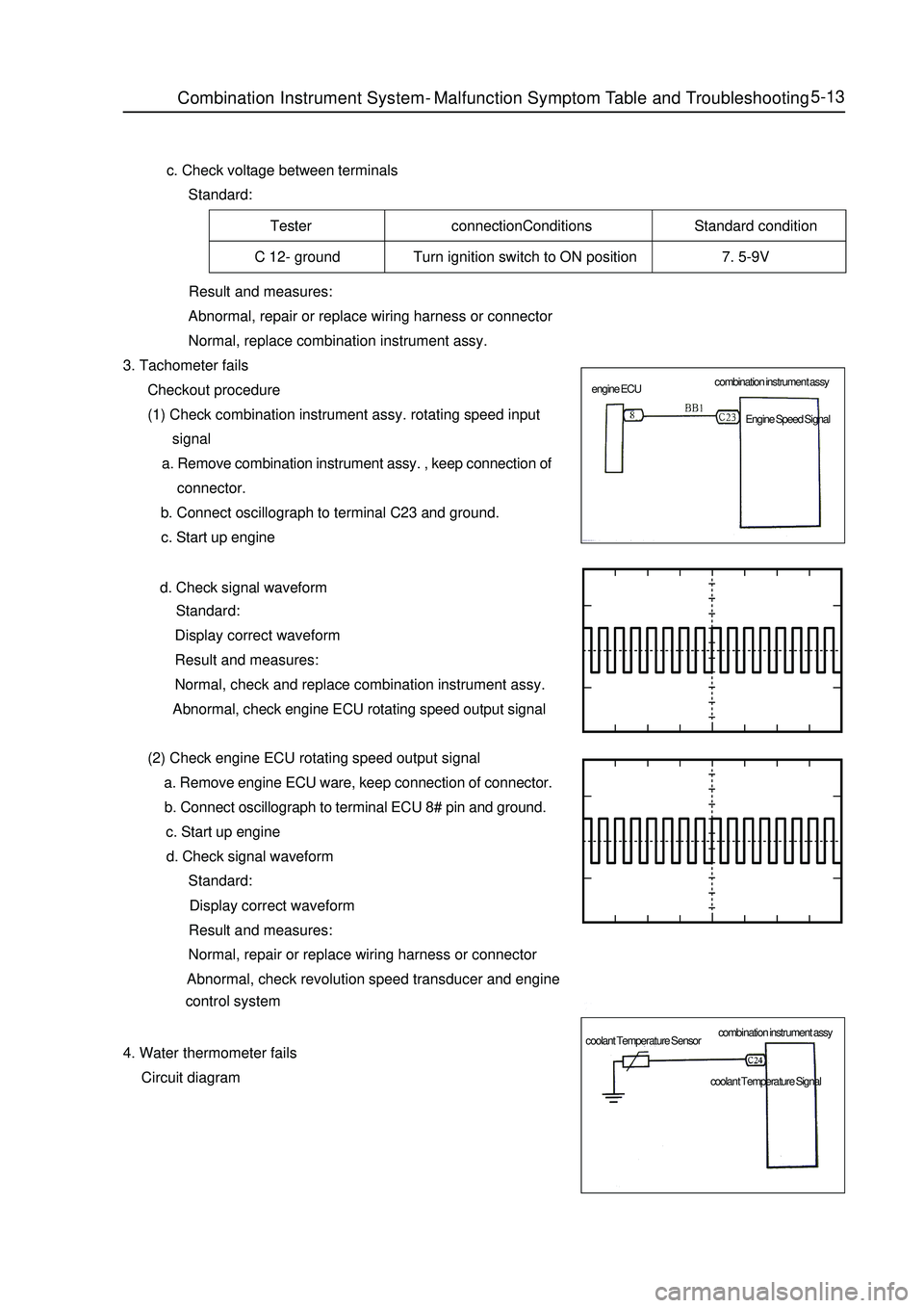
5-13 c. Check voltage between terminals
Standard:Tester connectionConditions Standard condition
C 12- ground Turn ignition switch to ON position 7. 5-9V
Result and measures:
Abnormal, repair or replace wiring harness or connector
Normal, replace combination instrument assy.
3. Tachometer fails
Checkout procedure
(1) Check combination instrument assy. rotating speed input
signal
a. Remove combination instrument assy. , keep connection of
connector.
b. Connect oscillograph to terminal C23 and ground.
c. Start up engine
d. Check signal waveform
Standard:
Display correct waveform
Result and measures:
Normal, check and replace combination instrument assy.
Abnormal, check engine ECU rotating speed output signal
(2) Check engine ECU rotating speed output signal
a. Remove engine ECU ware, keep connection of connector.
b. Connect oscillograph to terminal ECU 8# pin and ground.
c. Start up engine
d. Check signal waveform
Standard:
Display correct waveform
Result and measures:
Normal, repair or replace wiring harness or connector
Abnormal, check revolution speed transducer and engine
control system
4. Water thermometer fails
Circuit diagramCombination Instrument System -Malfunction Symptom Table and Troubleshooting combination instrument assy
combination instrument assy engine ECU
coolant Temperature SensorEngine Speed Signal
coolant Temperature Signal
Page 201 of 416
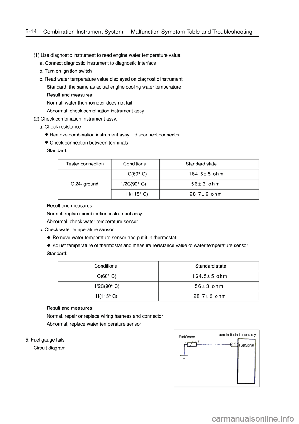
Tester connection Conditions Standard state
C(60°C)164.5±5 ohm
C 24- ground 1/2C(90°C)56±3 ohm
H(115°C)28.7±2 ohmConditions Standard state
C(60°C)164.5±5 ohm
1/2C(90°C)56±3 ohm
H(115°C)28.7±2 ohm5-14 (1) Use diagnostic instrument to read engine water temperature value
a. Connect diagnostic instrument to diagnostic interface
b. Turn on ignition switch
c. Read water temperature value displayed on diagnostic instrument
Standard: the same as actual engine cooling water temperature
Result and measures:
Normal, water thermometer does not fail
Abnormal, check combination instrument assy.
(2) Check combination instrument assy.
a. Check resistance
Remove combination instrument assy. , disconnect connector.
Check connection between terminals
Standard:
Result and measures:
Normal, replace combination instrument assy.
Abnormal, check water temperature sensor
b. Check water temperature sensor
Remove water temperature sensor and put it in thermostat.
Adjust temperature of thermostat and measure resistance value of water temperature sensor
Standard:
Result and measures:
Normal, repair or replace wiring harness and connector
Abnormal, replace water temperature sensor
5. Fuel gauge fails
Circuit diagramCombination Instrument System -Malfunction Symptom Table and Troubleshooting combination instrument assy
Fuel Sensor
Fuel Signal
Page 213 of 416

Chapter 4 Light SystemSection 1 Light System IntroductionI. Composition Light system comprises external illumination and signal system and internal illumination system.
The function of the external illumination and signal system is to illuminate the road ahead and send signals
to other vehicles.
The internal illumination system provides internal illumination for driver and passengers.II. Precaution for service1. Precaution when repairing electrical equipments
Disconnect the battery ground cable.
2. Precaution when replacing a headlamp bulb
(1) Before replacing a halogen bulb, turn the headlamp OFF to make it cool.
(2) When installing a new halogen bulb, do not touch the glass part of the bulb with bare hands.
(3) If there is oil stain on the surface of halogen bulb (headlamp and front fog lamp) when the lamps are
turned ON, its service life will be shortened.
(4) Halogen bulbs (headlamp and front fog lamp) have pressurized gas inside and require special handling.
They can explode if dropped to ground. The glass fragments will splash up.
(5) When replacing, make sure to use the bulbs with the same power, same model.
(6) After the bulb is installed, make the lamp holder tight.III. Bulb specificationsRemark: All bulbs are made by Philips Corp..Light System-
Light System Introduction5-26Name Specifications
Headlamp (High beam and Low beam) H1 12V 55W
Turn signal lamp PY21W 12V 21W
Position lamp W5W 12V 5W
Front fog lamp H3 12V 55W
Rear combination lamp (Turn signal lamp) PY21W 12V 21W
Rear combination lamp (Brake / Position lamp) P21/5W 12V 21/5W
Rear combination lamp (Rear fog lamp) P21W 12V 21W
Rear combination lamp (Back-up lamp) P21W 12V 21W
Interior lamp (dome lamp) R5W 12V 5W
Rear row reading lamp C5W 12V 5W
Side turn signal lamp W5W 12V 5W
High mounted stop lamp (incl. rear trunk lamp) W5W 12V 5W
License plate lamp W5W 12V 5W
Door courtesy lamp W5W 12V 5W