Engine GENESIS G80 2017 Owner's Manual
[x] Cancel search | Manufacturer: GENESIS, Model Year: 2017, Model line: G80, Model: GENESIS G80 2017Pages: 496, PDF Size: 12.82 MB
Page 418 of 496

7-41
7
Maintenance
For best battery service
The battery is in the trunk.
When replacing the battery, discon-
nect the negative (-) cable (1) and
remove the positive (+) battery fuse
box (2).
When you do not use the vehi-
cle for a long time in a low
temperature area, disconnect
the battery and keep it
indoors.
Always charge the battery
fully to prevent battery case
damage in low temperature
areas.
CAUTION
CALIFORNIA PROPOSITION 65
WARNING
Battery posts, terminals, and
related accessories contain
lead and lead compounds,
chemicals known to the State of
California to cause cancer, birth
defects and reproductive harm.
Batteries also contain other
chemicals known to the State of
California to cause cancer.
Wash hands after handling.
WARNING (Continued)
NEVER attempt to recharge
the battery when the vehicle’s
battery cables are connected
to the battery.
The electrical ignition system
works with high voltage.
NEVER touch these compo-
nents with the engine running
or when the Engine Start/Stop
button is in the ON position.
ODH073029
ODH073030
Page 420 of 496

7-43
7
Maintenance
By jump starting
After a jump start from a good bat-
tery, idle vehicle with headlights on
for 20-30 minutes and then drive the
vehicle for 20-30 minutes before it is
shut off. The vehicle may not restart
if you shut it off before the battery
had a chance to adequately
recharge. See "Jump Starting" in
chapter 6 for more information on
jump starting procedures.
✽ ✽NOTICE
An inappropriately disposed
battery can be harmful to
the environment and human
health. Dispose the battery
according to your local
law(s) or regulation.
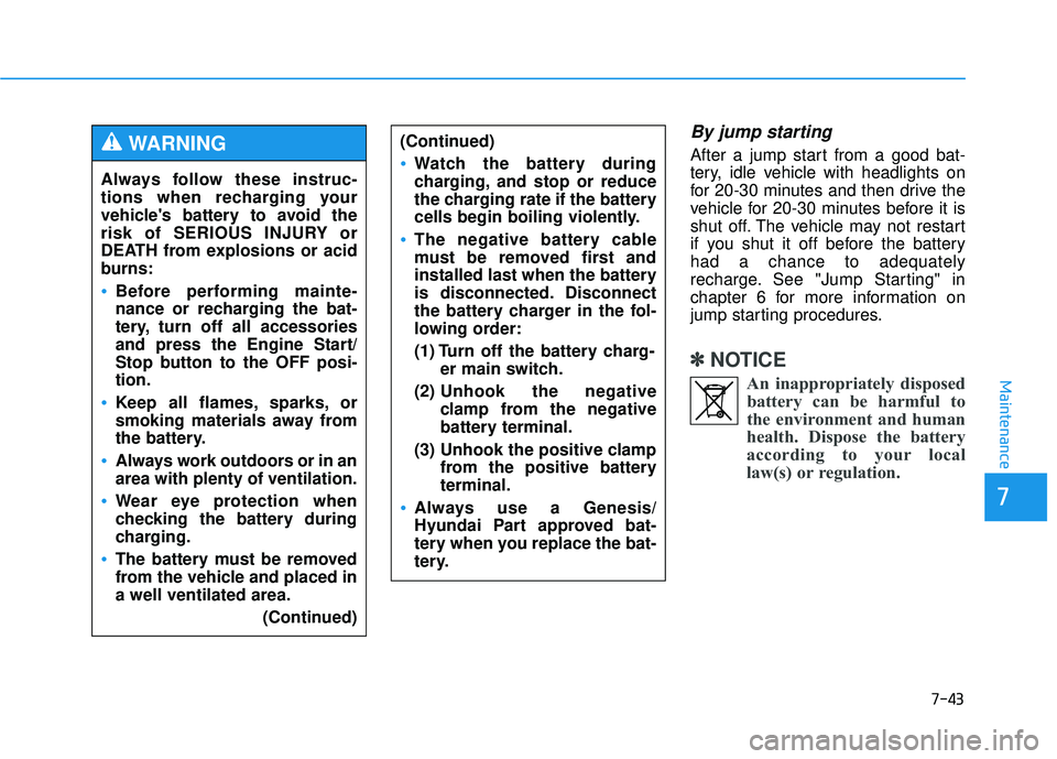
Always follow these instruc-
tions when recharging your
vehicle's battery to avoid the
risk of SERIOUS INJURY or
DEATH from explosions or acid
burns:
Before performing mainte-
nance or recharging the bat-
tery, turn off all accessories
and press the Engine Start/
Stop button to the OFF posi-
tion.
Keep all flames, sparks, or
smoking materials away from
the battery.
Always work outdoors or in an
area with plenty of ventilation.
Wear eye protection when
checking the battery during
charging.
The battery must be removed
from the vehicle and placed in
a well ventilated area.
(Continued)
WARNING (Continued)
Watch the battery during
charging, and stop or reduce
the charging rate if the battery
cells begin boiling violently.
The negative battery cable
must be removed first and
installed last when the battery
is disconnected. Disconnect
the battery charger in the fol-
lowing order:
(1) Turn off the battery charg-er main switch.
(2) Unhook the negative
clamp from the negative
battery terminal.
(3) Unhook the positive clamp from the positive battery
terminal.
Always use a Genesis/
Hyundai Part approved bat-
tery when you replace the bat-
tery.
Page 438 of 496

7-61
7
Maintenance
F
FU
U S
SE
E S
S
A vehicle's electrical system is pro-
tected from electrical overload dam-
age by fuses.
This vehicle has 2 (or 3) fuse panels,
one located in the driver's side panel
bolster, the other in the engine com-
partment near the battery.
If any of your vehicle's lights, acces-
sories, or controls do not work, check
the appropriate circuit fuse. If a fuse
has blown, the element inside the
fuse will be melted or broken.
If the electrical system does not
work, first check the driver's side
fuse panel. Before replacing a blown
fuse, disconnect the negative battery
cable. Always replace a blown fuse
with one of the same rating.
If the replacement fuse blows, this
indicates an electrical problem. Avoid
using the system involved and imme-
diately consult an authorized retailer
of Genesis Branded products.✽ ✽
NOTICE
Three kinds of fuses are used: blade
type for lower amperage rating, car-
tridge type, and fusible link for
higher amperage ratings.
NEVER replace a fuse with any-
thing but another fuse of the
same rating.
A higher capacity fuse could
cause damage and possibly
cause a fire.
Do not install a wire or alu-
minum foil instead of the
proper fuse - even as a tem-
porary repair. It may cause
extensive wiring damage and
possibly a fire.
WARNING
Normal
Normal
■
Blade type
■ Cartridge type
■ Multi fuse Blown
Blown
Normal Blown
■Fusible link
Normal Blown
OLMB073029/OBH072060
Page 439 of 496

7-62
Maintenance
Instrument panel fuse replace-
ment
1. Turn the engine off.
2. Turn all other switches OFF.
3. Open the fuse panel cover.
4. Refer to the label on the inside ofthe fuse panel cover to locate the
suspected fuse location. 5. Pull the suspected fuse straight
out. Use the removal tool provided
in the engine compartment fuses
panel.
6. Remove and check the suspected fuse; replace it if it is blown. Spare
fuses are provided in the instru-
ment panel fuse panels (or in the
engine compartment fuse panel).
7. Push in a new fuse of the same rating, and make sure it fits tightly
in the clips. If it fits loosely, consult
an authorized retailer of Genesis
Branded products.
Do not use a screwdriver or any
other metal object to remove
fuses because it may cause a
short circuit and damage the
system.
CAUTION
ODH073054
ODH073031
Page 440 of 496

7-63
7
Maintenance
In an emergency, if you do not have
a spare fuse, use a fuse of the same
rating from a circuit you may not
need for operating the vehicle, such
as the cigarette lighter fuse.
If the headlamps or other electrical
components do not work and the
fuses are OK, check the fuse panel
in the engine compartment. If a fuse
is blown, it must be replaced with the
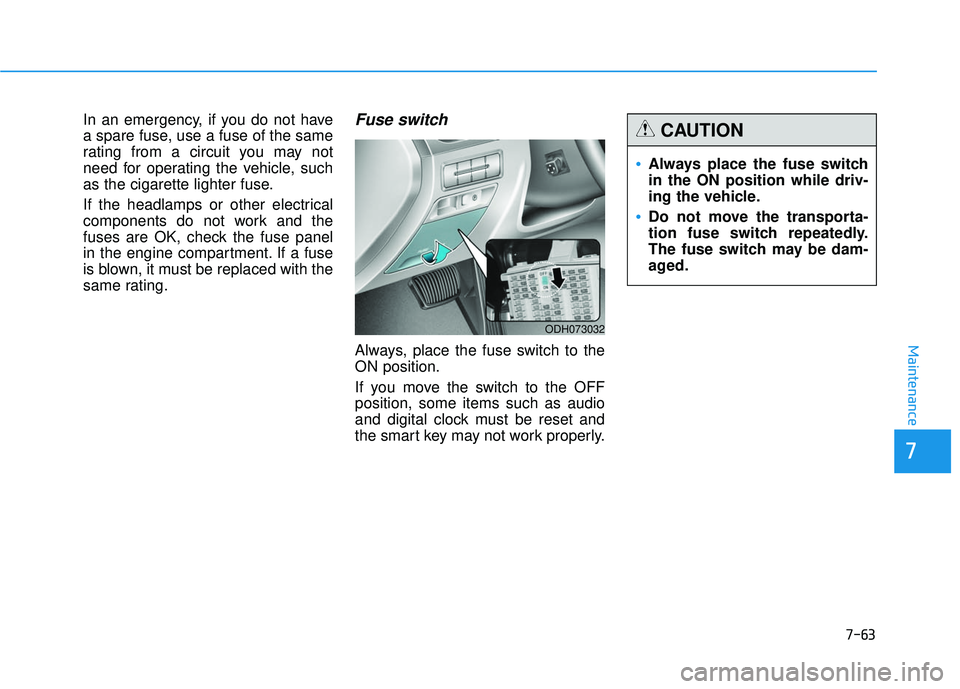
same rating.Fuse switch
Always, place the fuse switch to the
ON position.
If you move the switch to the OFF
position, some items such as audio
and digital clock must be reset and
the smart key may not work properly.
ODH073032
Always place the fuse switch
in the ON position while driv-
ing the vehicle.
Do not move the transporta-
tion fuse switch repeatedly.
The fuse switch may be dam-
aged.
CAUTION
Page 441 of 496

7-64
Maintenance
Engine compartment panel
fuse replacement
1. Turn the engine off.
2. Turn all other switches OFF.
3. Remove the fuse panel cover bypressing the tap and pulling up. 4. Remove and check the suspected
fuse; replace it if it is blown. To
remove or insert the fuse, use the
fuse puller in the engine compart-
ment fuse panel.
5. Push in a new fuse of the same rating, and make sure it fits tightly
in the clips. If it fits loosely, consult
an authorized retailer of Genesis
Branded products.
Main fuse
If the main fuse is blown, it must be
removed as follows:
1. Turn off the engine.
2. Disconnect the negative batterycable.
3. Remove the fuse panel cover by pressing the tab and pulling it up.
4. Remove the nuts shown in the pic- ture above.
5. Replace the fuse with a new one of the same rating.
6. Reinstall in the reverse order of removal.
ODH073054
ODH073056
ODH073057A
Page 442 of 496

7-65
7
Maintenance
✽
✽NOTICE
If the main fuse is blown, consult an
authorized retailer of Genesis
Branded products.
Multi fuse
If the multi fuse is blown, it must be
removed as follows:
1. Turn off the engine.
2. Disconnect the negative battery
cable.
3. Remove the fuse panel cover by pressing the tab and pulling up.
4. Remove the bolts shown in the picture above.
5. Replace the fuse with a new one of the same rating.
6. Reinstall in the reverse order of removal.
✽ ✽NOTICE
If the multi fuse is blown, consult an
authorized retailer of Genesis
Branded products.
ODH073055
Page 447 of 496

7-70
Maintenance
Engine compartment fuse panel
Inside the fuse/relay box cover, you
can find the fuse/relay label describ-
ing fuse/relay name and capacity.
✽ ✽NOTICE
Not all fuse panel descriptions in
this manual may be applicable to
your vehicle; the information is
accurate at the time of printing.
When you inspect the fuse panel in
your vehicle, refer to the fuse panel
label.
ODH073033
ODH073034
Page 448 of 496

7-71
7
Maintenance
Engine compartment main fuse panel
Fuse NameFuse ratingCircuit Protected
ALT200AAlternator, Multifuse (BATT) - B+2/ B+5/ MDPS 1/ C/FAN, Fuse - P/SEAT DRV 2/ P/SEAT RR/ SEAT
LUMBAR/ ESC 1/ ESC 2
1 B+ 60A IGPM (Fuse - BRAKE SWITCH, Leak Current Autocut Device (Fuse - INTERIOR LAMP/ MULTI MEDIA 1/
MEMORY 1/ MEMORY 2/ MEMORY 3), IPS 1)
3B+ 60A IGPM (Fuse - SMART KEY 1/ SMART KEY 2/ MODULE 1/ B/A HORN, IPS 2/IPS 3/IPS 5/IPS 7)
4B+60A IGPM (Fuse - DOOR LAMP/ STOP LAMP, IPS 4/IPS 6)
6B+60A Metal Core Block (PCB #1 Fuse - ECU 3/ IG2/ MODULE 1)
7B+80A Metal Core Block (PCB #2 Fuse - HORN/ ACC/ EPB 1/ EPB 2)
2 B+ 60A IGPM (Fuse - P/HANDLE/ P/WDW LH/ P/SEAT PASS 1/ S/HEATER PASS/ MODULE 10/ SUNROOF/
P/DOOR DRV/ P/DOOR PASS)
C/FAN 70A RLY. 1 (C/Fan Relay)
5 B+ 80A Metal Core Block (PCB #1 Fuse - BLOWER/ DEICER/ H/LAMP WASHER)
MDPS 1 125A MDPS Unit
B/UP LAMP 10A TCM, Transmission Range Switch, Rear Combination Lamp (IN) LH/RH, Electro Chr\
omic Mirror, A/V &
Navigation Head Unit
P/SEAT RR 30A Not Used
1 ESC40A ESC Module, Multipurpose Check Connector
2 ESC40A ESC Module, Multipurpose Check Connector
Page 450 of 496

7-73
7
Maintenance
Fuse NameFuse ratingCircuit Protected
IG230A IG2 Relay
3ECU30A Engine Control Relay
1 MODULE 10A 4WD ECM, Smart Cruise Control Radar, Active Air Flap
2WIPER10A Metal Core Block (PCB #2 - Wiper Relay)
WASHER 20A Washer Relay
2SENSOR 10A ECM, Oxygen Sensor #1/#2/#3/#4
1 SENSOR10A ECM, Oil Control Valve #1/#2/#3/#4, Canister Close Valve, Purge Control Solenoid Valve, Variable Intake
Solenoid Valve #1/#2
3 SENSOR10A ECM, Rear Junction Block (Fuel Pump Relay)
4 SENSOR10A C/Fan Relay, Camshaft Position Valve (G8BE)
INJECTOR 15A Injector Drive Box
IGN COIL 20A G6DJ : Condenser, Ignition Coil #1/#2/#3/#4/#5/#6, G8BE : Condenser #1/#2, Ignition Coil
#1/#2/#3/#4/#5/#6/#7/#8
DEICER 20A Metal Core Block (PCB #2 - Front Deicer Relay)
H/LAMP WASHER 25A Head Lamp Washer Relay
2A/CON10A A/C Control Module
BLOWER 40A Blower Relay