section 3 GENESIS G90 2017 User Guide
[x] Cancel search | Manufacturer: GENESIS, Model Year: 2017, Model line: G90, Model: GENESIS G90 2017Pages: 524, PDF Size: 19.3 MB
Page 223 of 524

To prevent damage to the conduc-
tors bonded to the inside surface
of the rear window, never use
sharp instruments or window
cleaners containing abrasives to
clean the window.
If you want to defrost and defog
the front windshield, refer to the
"Windshield Defrosting and
Defogging" section in this chapter.
Rear Window Defroster
The defroster heats the window to
remove frost, fog and thin ice from
the interior and exterior of the rear
window, while engine is running.
To activate the rear window defroster,
press the rear window defroster but-
ton located in the center facia switch
panel. The indicator on the rear win-
dow defroster button illuminates
when the defroster is ON.
To turn off the defroster, press therear window defroster button again.
Information
• If there is heavy accumulation ofsnow on the rear window, brush it off
before operating the rear defroster.
• The rear window defroster automat- ically turns off after approximately
20 minutes or when the Engine
Start/Stop button is in the OFF posi-
tion.
Side view mirror defroster
If your vehicle is equipped with the
side view mirror defrosters, they will
operate at the same time you turn on
the rear window defroster.
Front Wiper Deicer
If your vehicle is equipped with the
front wiper deicer, it will be operating
at the same time you operate the
rear window defroster.
iNOTICE
D DE
EF
FR
R O
O S
ST
T E
ER
R
3-121
03
OHI046304
Page 229 of 524
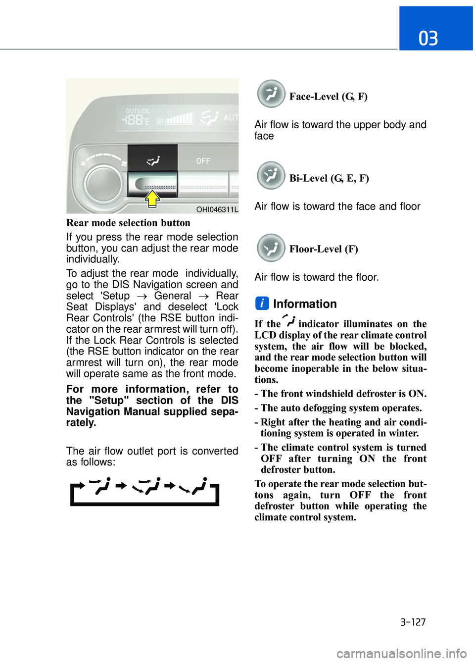
Rear mode selection button
If you press the rear mode selection
button, you can adjust the rear mode
individually.
To adjust the rear mode individually,
go to the DIS Navigation screen and
select 'Setup →General →Rear
Seat Displays' and deselect 'Lock
Rear Controls' (the RSE button indi-
cator on the rear armrest will turn off).
If the Lock Rear Controls is selected
(the RSE button indicator on the rear
armrest will turn on), the rear mode
will operate same as the front mode.
For more information, refer to
the "Setup" section of the DIS
Navigation Manual supplied sepa-
rately.
The air flow outlet port is converted
as follows: Face-Level (G, F)
Air flow is toward the upper body and
face
Bi-Level (G, E, F)
Air flow is toward the face and floor
Floor-Level (F)
Air flow is toward the floor.
Information
If the indicator illuminates on the
LCD display of the rear climate control
system, the air flow will be blocked,
and the rear mode selection button will
become inoperable in the below situa-
tions.
- The front windshield defroster is ON.
- The auto defogging system operates.
- Right after the heating and air condi- tioning system is operated in winter.
- The climate control system is turned OFF after turning ON the front
defroster button.
To operate the rear mode selection but-
tons again, turn OFF the front
defroster button while operating the
climate control system.
i
3-127
03
OHI046311L
Page 235 of 524
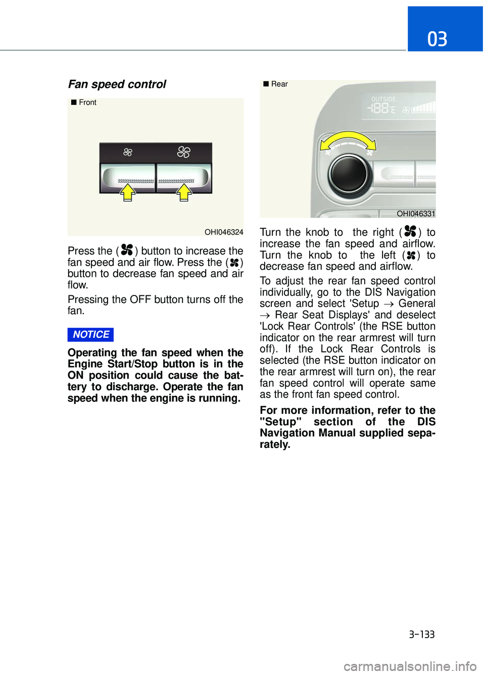
Fan speed control
Press the ( ) button to increase the
fan speed and air flow. Press the ( )
button to decrease fan speed and air
flow.
Pressing the OFF button turns off the
fan.
Operating the fan speed when the
Engine Start/Stop button is in the
ON position could cause the bat-
tery to discharge. Operate the fan
speed when the engine is running.Turn the knob to the right ( ) to
increase the fan speed and airflow.
Turn the knob to the left ( ) to
decrease fan speed and airflow.
To adjust the rear fan speed control
individually, go to the DIS Navigation
screen and select 'Setup →
General
→ Rear Seat Displays' and deselect
'Lock Rear Controls' (the RSE button
indicator on the rear armrest will turn
off). If the Lock Rear Controls is
selected (the RSE button indicator on
the rear armrest will turn on), the rear
fan speed control will operate same
as the front fan speed control.
For more information, refer to the
"Setup" section of the DIS
Navigation Manual supplied sepa-
rately.
NOTICE
3-133
03
OHI046324
■
Front
OHI046331
■
Rear
Page 380 of 524
Jump starting can be dangerous if
done incorrectly. Follow the jump
starting procedure in this section to
avoid serious injury or damage to
your vehicle. If in doubt about how to
properly jump start your vehicle, we
strongly recommend that you have a
service technician or towing service
do it for you.
J JU
U M
M P
P
S
S T
T A
A R
RT
TI
IN
N G
G
6-5
06
To prevent SERIOUS INJURY or
DEATH to you or bystanders,
always follow these precautions
when working near or handling
the battery:
Always read and follow
instructions carefully
when handling a battery.
Wear eye protection
designed to protect the
eyes from acid splashes.
Keep all flames, sparks, or
smoking materials away
from the battery.
Hydrogen is always pres- ent in battery cells, is
highly combustible, and
may explode if ignited.
Keep batteries out of
reach of children. (Continued)
(Continued)Batteries contain sulfu-
ric acid which is highly
corrosive. Do not allow
acid to contact your
eyes, skin or clothing.
If acid gets into your eyes, flush
your eyes with clean water for at
least 15 minutes and get imme-
diate medical attention. If acid
gets on your skin, thoroughly
wash the area. If you feel pain or
a burning sensation, get med-
ical attention immediately.
• When lifting a plastic-cased battery, excessive pressure
on the case may cause battery
acid to leak. Lift with a battery
carrier or with your hands on
opposite corners.
Do not attempt to jump start your vehicle if your battery is
frozen.
NEVER attempt to recharge the battery when the vehicle's
battery cables are connected
to the battery.
The electrical ignition system works with high voltage.
NEVER touch these compo-
nents with the engine running
or when the Engine Start/Stop
button is in the ON position.
WARNING
Page 391 of 524
6-16
What to do in an emergency
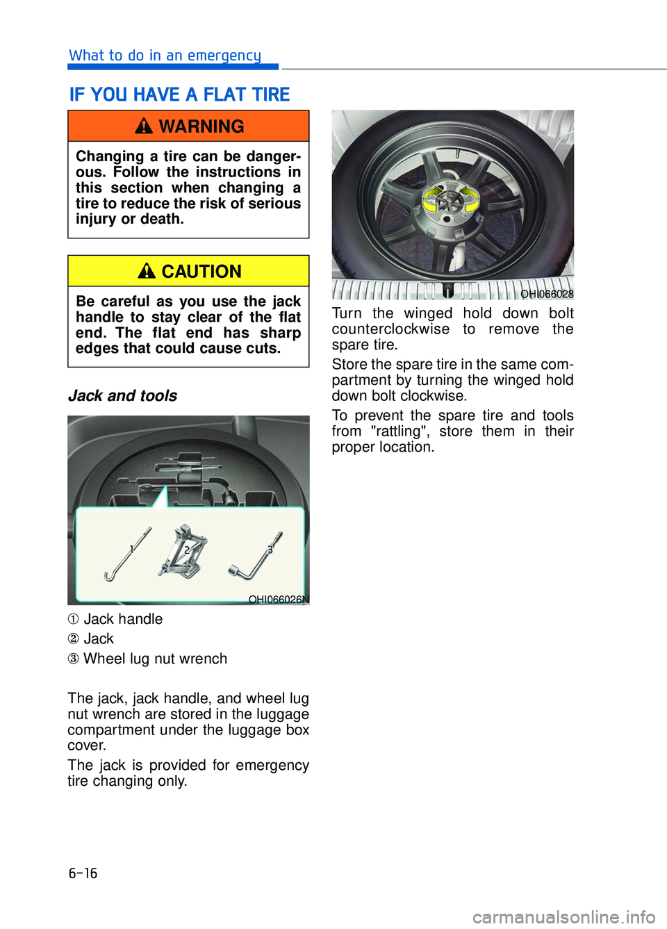
Jack and tools
➀Jack handle
② Jack
③ Wheel lug nut wrench
The jack, jack handle, and wheel lug
nut wrench are stored in the luggage
compartment under the luggage box
cover.
The jack is provided for emergency
tire changing only. Turn the winged hold down bolt
counterclockwise to remove the
spare tire.
Store the spare tire in the same com-
partment by turning the winged hold
down bolt clockwise.
To prevent the spare tire and tools
from "rattling", store them in their
proper location.
I I
F
F
Y
Y O
O U
U
H
H A
AV
VE
E
A
A
F
F L
LA
A T
T
T
T I
IR
R E
E
Changing a tire can be danger-
ous. Follow the instructions in
this section when changing a
tire to reduce the risk of serious
injury or death.
WARNING
OHI066028
OHI066026N
Be careful as you use the jack
handle to stay clear of the flat
end. The flat end has sharp
edges that could cause cuts.
CAUTION
Page 423 of 524
7-21
07
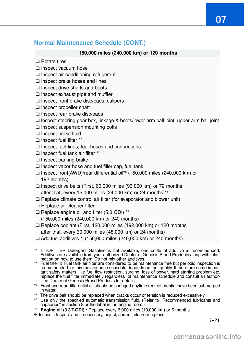
Normal Maintenance Schedule (CONT.)
150,000 miles (240,000 km) or 120 months
❑Rotate tires
❑ Inspect vacuum hose
❑ Inspect air conditioning refrigerant
❑ Inspect brake hoses and lines
❑ Inspect drive shafts and boots
❑ Inspect exhaust pipe and muffler
❑ Inspect front brake disc/pads, calipers
❑ Inspect propeller shaft
❑ Inspect rear brake disc/pads
❑ Inspect steering gear box, linkage & boots/lower arm ball joint, upper arm ball joint
❑ Inspect suspension mounting bolts
❑ Inspect brake fluid
❑ Inspect fuel filter *
2
❑Inspect fuel lines, fuel hoses and connections
❑ Inspect fuel tank air filter *2
❑Inspect parking brake
❑ Inspect vapor hose and fuel filler cap, fuel tank
❑ Inspect front(AWD)/rear differential oil*
3(150,000 miles (240,000 km) or
192 months)
❑ Inspect drive belts (First, 60,000 miles (96,000 km) or 72 months
after that, every 15,000 miles (24,000 km) or 24 months)*
4
❑ Replace climate control air filter (for evaporator and blower unit)
❑ Replace air cleaner filter
❑ Replace engine oil and filter (5.0 GDI) *
6
(150,000 miles (240,000 km) or 240 months)
❑ Replace coolant (First, 120,000 miles (192,000 km) or 120 months
after that, every 30,000 miles (48,000 km) or 24 months)
❑ Add fuel additives *
1(150,000 miles (240,000 km) or 240 months)
*1: If TOP TIER Detergent Gasoline is not available, one bottle of additive is recommended.
Additives are available from your authorized Dealer of Genesis Brand Products along with infor-
mation on how to use them. Do not mix other additives.
*
2: Fuel filter & Fuel tank air filter are considered to be maintenance free\
but periodic inspection is recommended for this maintenance schedule depends on fuel quality. If there are some impor-
tant safety matters like fuel flow restriction, surging, loss of power, hard starting problem etc,
replace the fuel filter immediately regardless of maintenance schedule \
and consult an author-
ized Dealer of Genesis Brand Products for details.
*
3: Front and rear differential oil should be changed anytime rear differential have been submerged in water.
*
4: The drive belt should be replaced when cracks occur or tension is reduced excessively.
*5: Use only the specified automatic transmission fluid. (Refer to "Recommended lubricants and capacities" in section 8 or the label in the engine room.)
*
6: Engine oil (3.3 T-GDI) : Replace every 6,000 miles (10,000 km) or 6 months.
❈ Inspect : Inspect and if necessary, adjust, correct, clean or replace.
Page 451 of 524
7-49
07
Tire Traction
Tire traction can be reduced if you
drive on worn tires, tires that are
improperly inflated or on slippery
road surfaces. Tires should be
replaced when tread wear indicators
appear. To reduce the possibility of
losing control, slow down whenever
there is rain, snow or ice on the road.
Tire Maintenance
In addition to proper inflation, correct
wheel alignment helps to decrease
tire wear. If you find a tire is worn
unevenly, have your dealer check the
wheel alignment.
When you have new tires installed,
make sure they are balanced. This
will increase vehicle ride comfort and
tire life. Additionally, a tire should
always be rebalanced if it is removed
from the wheel.
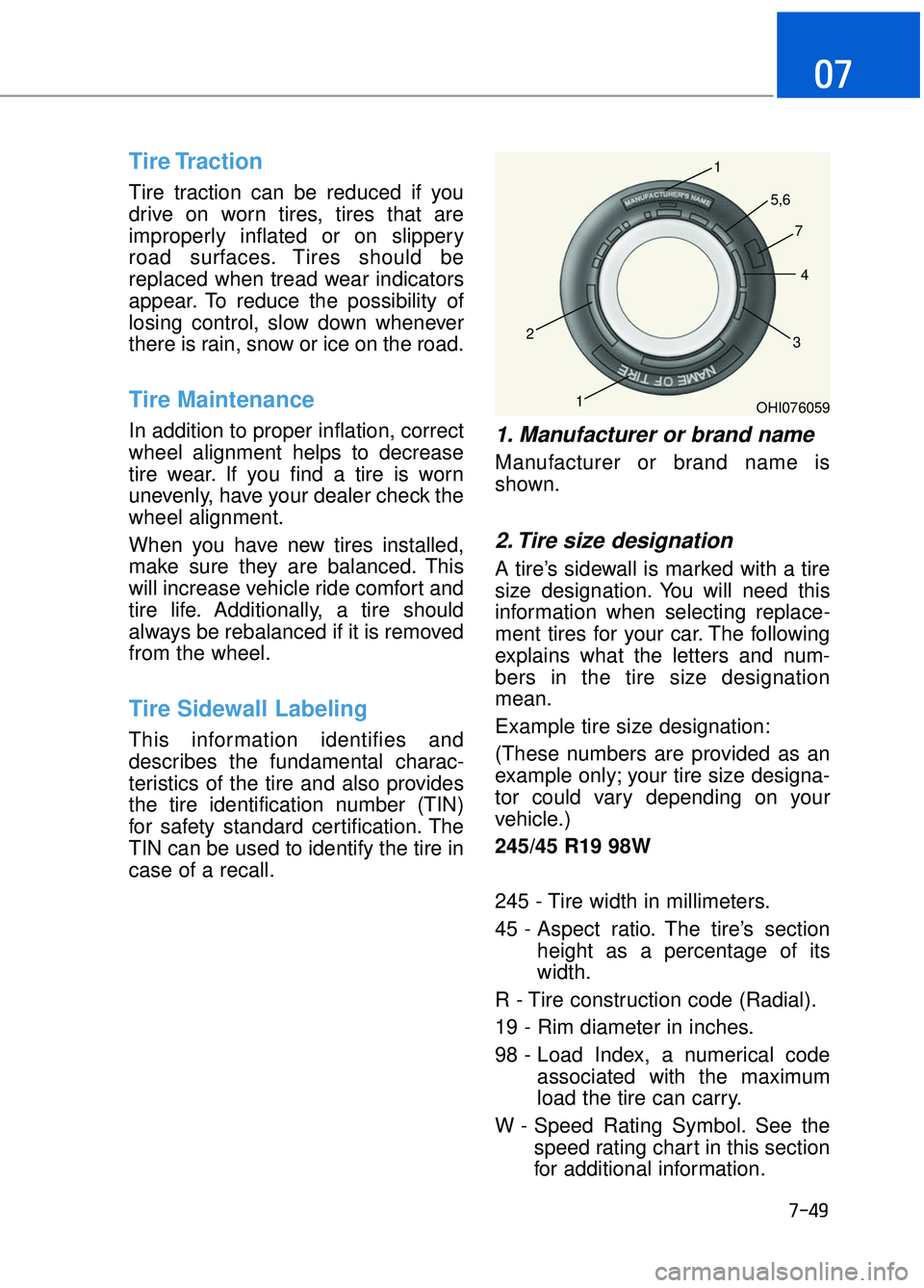
Tire Sidewall Labeling
This information identifies and
describes the fundamental charac-
teristics of the tire and also provides
the tire identification number (TIN)
for safety standard certification. The
TIN can be used to identify the tire in
case of a recall.
1. Manufacturer or brand name
Manufacturer or brand name is
shown.
2. Tire size designation
A tire’s sidewall is marked with a tire
size designation. You will need this
information when selecting replace-
ment tires for your car. The following
explains what the letters and num-
bers in the tire size designation
mean.
Example tire size designation:
(These numbers are provided as an
example only; your tire size designa-
tor could vary depending on your
vehicle.)
245/45 R19 98W
245 - Tire width in millimeters.
45 - Aspect ratio. The tire’s sectionheight as a percentage of its
width.
R - Tire construction code (Radial).
19 - Rim diameter in inches.
98 - Load Index, a numerical code associated with the maximum
load the tire can carry.
W - Speed Rating Symbol. See the speed rating chart in this section
for additional information.
OHI076059
1
1
2
34
5,6
7
Page 453 of 524

7-51
07
4. Tire ply composition andmaterial
The number of layers or plies of rub-
ber-coated fabric in the tire. Tire
manufacturers also must indicate the
materials in the tire, which include
steel, nylon, polyester, and others.
The letter "R" means radial ply con-
struction; the letter "D" means diago-
nal or bias ply construction; and the
letter "B" means belted-bias ply con-
struction.
5. Maximum permissible infla-tion pressure
This number is the greatest amount
of air pressure that should be put in
the tire. Do not exceed the maximum
permissible inflation pressure. Refer
to the Tire and Loading Information
label for recommended inflation
pressure.
6. Maximum load rating
This number indicates the maximum
load in kilograms and pounds that
can be carried by the tire. When
replacing the tires on the vehicle,
always use a tire that has the same
load rating as the factory installed
tire.
7. Uniform tire quality grading
Quality grades can be found where
applicable on the tire sidewall
between tread shoulder and maxi-
mum section width.
For example:
TREAD wear 200
TRACTION AA
TEMPERATURE A
Tread wear
The tread wear grade is a compara-
tive rating based on the wear rate of
the tire when tested under controlled
conditions on a specified govern-
ment test course. For example, a tire
graded 150 would wear one-and-a-
half times (1½) as well on the gov-
ernment course as a tire graded 100.
The relative performance of tires
depends upon the actual conditions
of their use, however, and may
depart significantly from the norm
due to variations in driving habits,
service practices and differences in
road characteristics and climate.
These grades are molded on the
sidewalls of passenger vehicle tires.
The tires available as standard or
optional equipment on your vehicle
may vary with respect to grade.
Page 493 of 524

7-91
07
Perchlorate Material-special handling may apply, See: www.dtsc.ca.gov/haz-
ardouswaste/perchlorate.
Notice to California Vehicle Dismantlers:
Perchlorate containing materials, such as air bag inflators, seatbelt preten-
sioners and keyless remote entry batteries, must be disposed of according to
Title 22 California Code of Regulations Section 67384.10 (a).
C CA
A L
LI
IF
F O
O R
RN
N I
IA
A
P
P E
ER
R C
CH
H L
LO
O R
RA
A T
TE
E
N
N O
O T
TI
IC
C E
E