torque GENESIS G90 2017 Owner's Manual
[x] Cancel search | Manufacturer: GENESIS, Model Year: 2017, Model line: G90, Model: GENESIS G90 2017Pages: 524, PDF Size: 19.3 MB
Page 300 of 524
5-39
05
Indicator lights
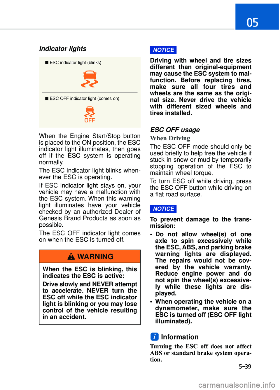
When the Engine Start/Stop button
is placed to the ON position, the ESC
indicator light illuminates, then goes
off if the ESC system is operating
normally.
The ESC indicator light blinks when-
ever the ESC is operating.
If ESC indicator light stays on, your
vehicle may have a malfunction with
the ESC system. When this warning
light illuminates have your vehicle
checked by an authorized Dealer of
Genesis Brand Products as soon as
possible.
The ESC OFF indicator light comes
on when the ESC is turned off.Driving with wheel and tire sizes
different than original-equipment
may cause the ESC system to mal-
function. Before replacing tires,
make sure all four tires and
wheels are the same as the origi-
nal size. Never drive the vehicle
with different sized wheels and
tires installed.ESC OFF usage
When Driving
The ESC OFF mode should only be
used briefly to help free the vehicle if
stuck in snow or mud by temporarily
stopping operation of the ESC to
maintain wheel torque.
To turn ESC off while driving, press
the ESC OFF button while driving on
a flat road surface.
To prevent damage to the trans-
mission:
Do not allow wheel(s) of one
axle to spin excessively while
the ESC, ABS, and parking brake
warning lights are displayed.
The repairs would not be cov-
ered by the vehicle warranty.
Reduce engine power and do
not spin the wheel(s) excessive-
ly while these lights are dis-
played.
When operating the vehicle on a dynamometer, make sure the
ESC is turned off (ESC OFF light
illuminated).
Information
Turning the ESC off does not affect
ABS or standard brake system opera-
tion.
i
NOTICE
NOTICE
■ ESC indicator light (blinks)
■ ESC OFF indicator light (comes on)
When the ESC is blinking, this
indicates the ESC is active:
Drive slowly and NEVER attempt
to accelerate. NEVER turn the
ESC off while the ESC indicator
light is blinking or you may lose
control of the vehicle resulting
in an accident.
WARNING
Page 306 of 524
5-45
05
SMART mode
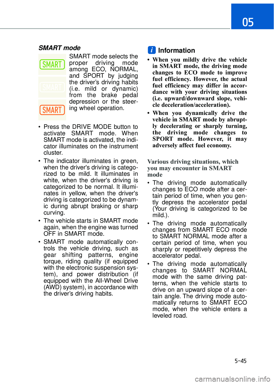
SMART mode selects the
proper driving mode
among ECO, NORMAL,
and SPORT by judging
the driver’s driving habits
(i.e. mild or dynamic)
from the brake pedal
depression or the steer-
ing wheel operation.
Press the DRIVE MODE button to activate SMART mode. When
SMART mode is activated, the indi-
cator illuminates on the instrument
cluster.
The indicator illuminates in green, when the driver's driving is catego-
rized to be mild. It illuminates in
white, when the driver's driving is
categorized to be normal. It illumi-
nates in yellow, when the driver's
driving is categorized to be dynam-
ic during abrupt braking or sharp
curving.
The vehicle starts in SMART mode again, when the engine was turned
OFF in SMART mode.
SMART mode automatically con- trols the vehicle driving, such as
gear shifting patterns, engine
torque, riding quality (if equipped
with the electronic suspension sys-
tem), and power distribution (if
equipped with the All-Wheel Drive
(AWD) system), in accordance with
the driver’s driving habits.Information
• When you mildly drive the vehiclein SMART mode, the driving mode
changes to ECO mode to improve
fuel efficiency. However, the actual
fuel efficiency may differ in accor-
dance with your driving situations
(i.e. upward/downward slope, vehi-
cle deceleration/acceleration).
• When you dynamically drive the vehicle in SMART mode by abrupt-
ly decelerating or sharply turning,
the driving mode changes to
SPORT mode. However, it may
adversely affect fuel economy.
Various driving situations, which
you may encounter in SMART
mode
The driving mode automaticallychanges to ECO mode after a cer-
tain period of time, when you gen-
tly depress the accelerator pedal
(Your driving is categorized to be
mild.).
The driving mode automatically changes from SMART ECO mode
to SMART NORMAL mode after a
certain period of time, when you
sharply or repetitively depress the
accelerator pedal.
The driving mode automatically changes to SMART NORMAL
mode with the same driving pat-
terns, when the vehicle starts to
drive on an upward slope of a cer-
tain angle. The driving mode auto-
matically returns to SMART ECO
mode, when the vehicle enters a
leveled road.
i
Page 309 of 524
5-48
Driving your vehicle
When ECO mode is activated:
The acceleration response may beslightly reduced if the accelerator
pedal is depressed moderately.
The air conditioner performance may be limited.
The shift pattern of the automatic transmission may change.
The engine noise may be louder at some automatic transmission
shifts as down-shift requires press-
ing down more on the accelerator.
The above situations are normal
conditions when ECO mode is acti-
vated to improve fuel efficiency.
Limitation of ECO mode operation:
If the following conditions occur while
ECO mode is operating, the system
operation is limited even though
there is no change in the ECO indi-
cator.
When the coolant temperature is low:
The system will be limited until
engine performance becomes nor-
mal.
When driving up a hill: The system will be limited to gain
power when driving uphill because
engine torque is restricted.
When driving the vehicle with the automatic transmission gear shift
lever in manual mode.
The system will be limited accord-
ing to the shift location.
INDIVIDUAL mode
In INDIVIDUAL mode, thedriver can select separate
modes and combine them
on the DIS Navigation
System screen.
- Engine/Transmission:
ECO/SMART
- Steering wheel:COMFORT/SPORT
- Suspension:COMFORT +/
COMFORT/SPORT
- All-Wheel Drive (AWD) system:
ECO/COMFORT/SPORT
For more information, refer to the
separately supplied DIS Navigation
System manual.
When INDIVIDUAL mode is select- ed by pressing the DRIVE MODE
button, the INDIVIDUAL mode indi-
cator (blue color) will illuminate.
Page 333 of 524
5-72
Driving your vehicle
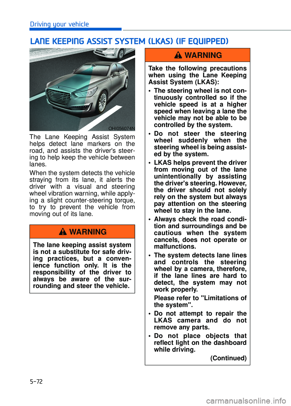
The Lane Keeping Assist System
helps detect lane markers on the
road, and assists the driver's steer-
ing to help keep the vehicle between
lanes.
When the system detects the vehicle
straying from its lane, it alerts the
driver with a visual and steering
wheel vibration warning, while apply-
ing a slight counter-steering torque,
to try to prevent the vehicle from
moving out of its lane.
L L A
A N
N E
E
K
K E
EE
EP
P I
IN
N G
G
A
A S
SS
SI
IS
S T
T
S
S Y
Y S
ST
T E
EM
M
(
( L
L K
K A
A S
S)
)
(
( I
IF
F
E
E Q
Q U
UI
IP
P P
PE
ED
D )
)
OHI056074N
The lane keeping assist system
is not a substitute for safe driv-
ing practices, but a conven-
ience function only. It is the
responsibility of the driver to
always be aware of the sur-
rounding and steer the vehicle.
WARNING
Take the following precautions
when using the Lane Keeping
Assist System (LKAS):
The steering wheel is not con-
tinuously controlled so if the
vehicle speed is at a higher
speed when leaving a lane the
vehicle may not be able to be
controlled by the system.
Do not steer the steering wheel suddenly when the
steering wheel is being assist-
ed by the system.
LKAS helps prevent the driver from moving out of the lane
unintentionally by assisting
the driver's steering. However,
the driver should not solely
rely on the system but always
pay attention on the steering
wheel to stay in the lane.
Always check the road condi- tion and surroundings and be
cautious when the system
cancels, does not operate or
malfunctions.
The system detects lane lines and controls the steering
wheel by a camera, therefore,
if the lane lines are hard to
detect, the system may not
work properly.
Please refer to "Limitations of
the system".
Do not attempt to repair the LKAS camera and do not
remove any parts.
Do not place objects that reflect light on the dashboard
while driving.
(Continued)
WARNING
Page 394 of 524
6-19
06
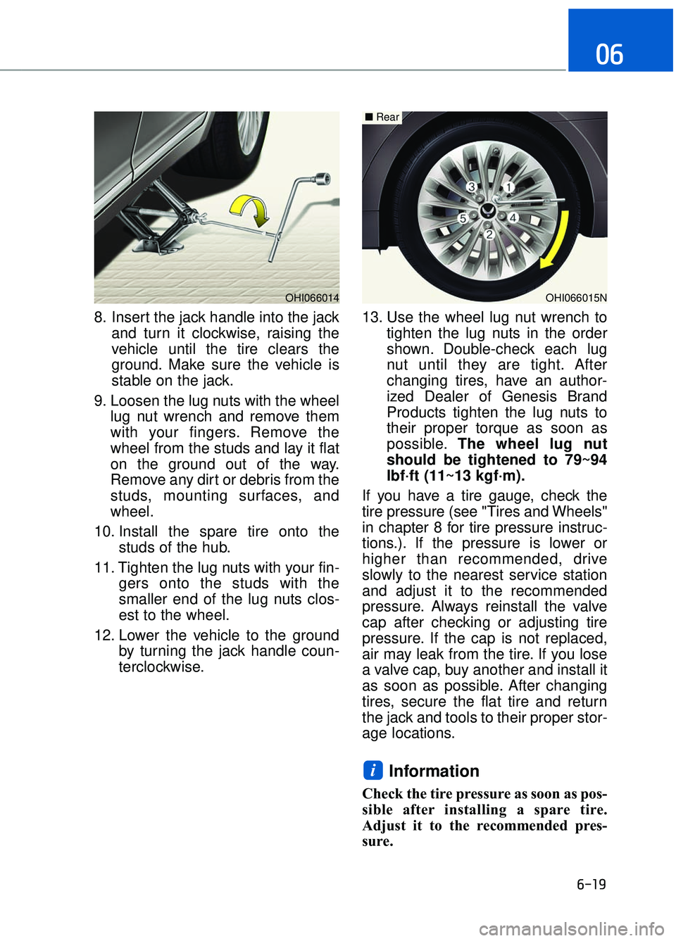
8. Insert the jack handle into the jackand turn it clockwise, raising the
vehicle until the tire clears the
ground. Make sure the vehicle is
stable on the jack.
9. Loosen the lug nuts with the wheel lug nut wrench and remove them
with your fingers. Remove the
wheel from the studs and lay it flat
on the ground out of the way.
Remove any dirt or debris from the
studs, mounting surfaces, and
wheel.
10. Install the spare tire onto the studs of the hub.
11. Tighten the lug nuts with your fin- gers onto the studs with the
smaller end of the lug nuts clos-
est to the wheel.
12. Lower the vehicle to the ground by turning the jack handle coun-
terclockwise. 13. Use the wheel lug nut wrench to
tighten the lug nuts in the order
shown. Double-check each lug
nut until they are tight. After
changing tires, have an author-
ized Dealer of Genesis Brand
Products tighten the lug nuts to
their proper torque as soon as
possible. The wheel lug nut
should be tightened to 79~94
lbf·ft (11~13 kgf·m).
If you have a tire gauge, check the
tire pressure (see "Tires and Wheels"
in chapter 8 for tire pressure instruc-
tions.). If the pressure is lower or
higher than recommended, drive
slowly to the nearest service station
and adjust it to the recommended
pressure. Always reinstall the valve
cap after checking or adjusting tire
pressure. If the cap is not replaced,
air may leak from the tire. If you lose
a valve cap, buy another and install it
as soon as possible. After changing
tires, secure the flat tire and return
the jack and tools to their proper stor-
age locations.
Information
Check the tire pressure as soon as pos-
sible after installing a spare tire.
Adjust it to the recommended pres-
sure.
i
OHI066015N
■ Rear
OHI066014
Page 396 of 524
6-21
06
When driving with the compact spare
tire mounted to your vehicle:
Check the tire pressure afterinstalling the compact spare tire.
The compact spare tire should be
inflated to 60 psi (420 kPa).
Do not take this vehicle through an automatic car wash while the com-
pact spare tire is installed.
Do not use the compact spare tire on any other vehicle because this
tire has been designed especially
for your vehicle.
The compact spare tire’s tread life is shorter than a regular tire.
Inspect your compact spare tire
regularly and replace worn com-
pact spare tires with the same size
and design, mounted on the same
wheel.
Do not use more than one compact spare tire at a time.Information
When the original tire and wheel are
repaired and reinstalled on the vehi-
cle, the lug nut torque must be set cor-
rectly. The correct lug nut tightening
torque is 79~94 lbf·ft (11~13 kgf·m).
To prevent damaging the compact
spare tire and your vehicle:
Drive slowly enough for the roadconditions to avoid all hazards,
such as a potholes or debris.
Avoid driving over obstacles. The compact spare tire diameter
is smaller than the diameter of a
conventional tire and reduces
the ground clearance approxi-
mately 1 inch (25 mm).
Do not use tire chains on the compact spare tire. Because of
the smaller size, a tire chain will
not fit properly.
Do not use the compact spare tire on any other wheels, nor
should standard tires, snow
tires, wheel covers or trim rings
be used with the compact spare
wheel.
NOTICE
i
Page 429 of 524
7-27
07
Brake Hoses and Lines
Visually check for proper installation,
chafing, cracks, deterioration and
any leakage. Replace any deteriorat-
ed or damaged parts immediately.
Brake Fluid
Check brake fluid level in the brake
fluid reservoir. The level should be
between the MIN and the MAX
marks on the side of the reservoir.
Use only hydraulic brake fluid con-
forming to DOT 3 or DOT 4 specifica-
tion.
Brake Transmission Fluid
Check the pads for excessive wear,
discs for run out and wear, and
calipers for fluid leakage.
Exhaust Pipe and Muffler
Visually inspect the exhaust pipes,
muffler and hangers for cracks, dete-
rioration, or damage. Start the
engine and listen carefully for any
exhaust gas leakage. Tighten con-
nections or replace parts as neces-
sary.
Suspension Mounting Bolts
Check the suspension connections
for looseness or damage. Retighten
to the specified torque.
Steering Gear Box, Linkage &
Boots/Lower Arm Ball Joint
With the vehicle stopped and the
engine off, check for excessive free-
play in the steering wheel. Check the
linkage for bends or damage. Check
the dust boots and ball joints for
deterioration, cracks, or damage.
Replace any damaged parts.
Drive Shafts and Boots
Check the drive shafts, boots and
clamps for cracks, deterioration, or
damage. Replace any damaged
parts and, if necessary, repack the
grease.
Air Conditioning Refrigerant
Check the air conditioning lines and
connections for leakage and dam-
age.
Page 447 of 524
7-45
07
Check Tire Inflation Pressure
Check your tires, including the spare
tire, once a month or more.
How to check
Use a good quality tire pressure
gauge to check tire pressure. You
can not tell if your tires are properly
inflated simply by looking at them.
Radial tires may look properly inflat-
ed when they are under-inflated.
Remove the valve cap from the tire
valve stem. Press the tire gauge firm-
ly onto the valve to get a pressure
measurement. If the cold tire inflation
pressure matches the recommended
pressure on the tire and loading
information label, no further adjust-
ment is necessary. If the pressure is
low, add air until you reach the rec-
ommended pressure. Make sure to
put the valve caps back on the valve
stems. Without the valve cap, dirt or
moisture could get into the valve
core and cause air leakage. If a valve
cap is missing, install a new one as
soon as possible.
If you overfill the tire, release air by
pushing on the metal stem in the
center of the tire valve. Recheck the
tire pressure with the tire gauge. Be
sure to put the valve caps back on
the valve stems. Without the valve
cap, dirt or moisture could get into
the valve core and cause air leakage.
If a valve cap is missing, install a new
one as soon as possible.
Tire Rotation
To equalize tread wear, Genesis
Brand recommends that the tires be
rotated every 7,500 miles (12,000
km) or sooner if irregular wear devel-
ops.
During rotation, check the tires for
correct balance.
When rotating tires, check for uneven
wear and damage. Abnormal wear is
usually caused by incorrect tire pres-
sure, improper wheel alignment, out-
of-balance wheels, severe braking or
severe cornering. Look for bumps or
bulges in the tread or side of tire.
Replace the tire if you find either of
these conditions. Replace the tire if
fabric or cord is visible. After rotation,
be sure to bring the front and rear tire
pressures to specification and check
lug nut tightness (proper torque is
79~94 lbf·ft [11~13 kgf·m]).
Page 497 of 524
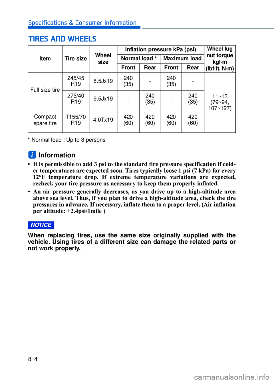
8-4
Specifications & Consumer information
* Normal load : Up to 3 persons
Information
• It is permissible to add 3 psi to the standard tire pressure specification if cold-er temperatures are expected soon. Tires typically loose 1 psi (7 kPa) for every
12°F temperature drop. If extreme temperature variations are expected,
recheck your tire pressure as necessary to keep them properly inflated.
• An air pressure generally decreases, as you drive up to a high-altitude area above sea level. Thus, if you plan to drive a high-altitude area, check the tire
pressures in advance. If necessary, inflate them to a proper level. (Air inflation
per altitude: +2.4psi/1mile )
When replacing tires, use the same size originally supplied with the
vehicle. Using tires of a different size can damage the related parts or
not work properly.
NOTICE
i
T T I
IR
R E
ES
S
A
A N
N D
D
W
W H
HE
EE
EL
LS
S
Item Tire size Wheel
size Inflation pressure kPa (psi)
Wheel lug
nut torque kgf·m
(lbf·ft, N·m)
Normal load * Maximum load
Front Rear Front Rear
Full size tire 245/45
R19 8.5Jx19 240
(35) -240
(35) -
11~13
(79~94,
107~127)
275/40
R19 9.5Jx19 - 240
(35) -240
(35)
Compact
spare tireT155/70 R194.0Tx19420
(60)420
(60)420
(60)420
(60)