engine GENESIS G90 2021 Owner's Manual
[x] Cancel search | Manufacturer: GENESIS, Model Year: 2021, Model line: G90, Model: GENESIS G90 2021Pages: 538, PDF Size: 13.02 MB
Page 469 of 538

7-29
07
Filter Replacement
Do not attempt to wash or to rinse it,
as water will damage the filter.
If soiled, the air cleaner filter must be
replaced.
Visit an authorized retailer of
Genesis Branded products to
replace the air cleaner filter.
Replace the filter according to the
Maintenance Schedule
Information
If the vehicle is operated in extremely
dusty or sandy areas, replace the air
cleaner filter more often than the
usual recommended intervals (refer to
"Maintenance Under Severe Usage
Conditions" in this chapter).• Do not drive with the air cleaner
filter removed. This will result in
excessive engine wear.
• When removing the air cleaner
filter, be careful that dust or dirt
does not enter the air intake, or
damage may result.
• Use Genuine Genesis Part, use
of non-Genuine Genesis Part
could damage the engine.
NOTICE
i
AIR CLEANER
OHI078018
Page 471 of 538

7-31
07
Blade Inspection
Contamination of either the wind-
shield or the wiper blades with for-
eign matter can reduce the effective-
ness of the windshield wipers.
Common sources of contamination
are insects, tree sap, and hot wax
treatments used by some commer-
cial car washes. If the blades are not
wiping properly, clean both the win-
dow and the blades with a good
cleaner or mild detergent, and rinse
thoroughly with clean water.
To prevent damage to the wiper
blades, arms or other compo-
nents, do not:
• Use gasoline, kerosene, paint
thinner, or other solvents on or
near them.
• Attempt to move the wipers
manually.
• Use non-specified wiper blades.
Information
Commercial hot waxes applied by
automatic car washes have been
known to make the windshield diffi-
cult to clean.
Blade Replacement
When the wipers no longer clean
adequately, the blades may be worn
or cracked, and require replacement.
• In order to prevent damage to
the hood and the wiper arms, the
wiper arms should only be lifted
when in the top wiping position.
• Always return the wiper arms to
the windshield before driving.
The use of a non-specified wiper
blade could result in wiper mal-
function and failure.
Front windshield wiper service
positions
1. Within 20 seconds of turning off
the engine, lift and hold the wiper
lever up to the MIST position for
about 2 seconds until the wipers
move to the top wipe position.
2. At this time you can lift the wipers
off the windshield.
3. Gently put the wipers back down
onto the windshield.
4. Turn the wipers to any ON position
to return the wipers to the bottom
resting position.
NOTICE
NOTICE
i
NOTICE
WIPER BLADES
OHI078019
Page 472 of 538

7-32
Maintenance
Front windshield wiper blade
replacement
1. Put the front windshield wipers
into the service position.
2. Open the wiper blade clip (1) and
slightly rotate the wiper blade
assembly (2) to expose the plastic
locking clip.3. Press the locking clip (3) and pull
down the wiper blade assembly
(4).
4. Remove the wiper blade assem-
bly from the wiper arm (5).
5. Install a blade assembly in the
reverse order of removal.
6. Return the wiper arm on the wind-
shield.
7. Place the Engine Start/Stop but-
ton to the ON position. The wiper
arms will return to the normal
operating position.
OHI078075
OHI078076
OHI078077
Page 475 of 538
7-35
07
Battery Recharging
By battery charger
Your vehicle has a maintenance-free,
calcium-based battery.
• If the battery becomes discharged
in a short time (because, for exam-
ple, the headlights or interior lights
were left on while the vehicle was
not in use), recharge it by slow
charging (trickle) for 10 hours.
• If the battery gradually discharges
because of high electric load while
the vehicle is being used, recharge
it at 20-30A for two hours.
AGM battery
• Absorbent Glass Matt (AGM)
batteries are maintenance-free
and we recommend that the
AGM battery be serviced by an
authorized retailer of Genesis
Branded products. For charging
your AGM battery, use only fully
automatic battery chargers that
are specially developed for AGM
batteries.
• When replacing the AGM bat-
tery, we recommend that you
use parts for replacement from
an authorized retailer of Genesis
Branded products.
• Do not open or remove the cap
on top of the battery. This may
cause leaks of internal elec-
trolyte that could result in
severe injury.
NOTICE
Always follow these instruc-
tions when recharging your
vehicle's battery to avoid the
risk of SERIOUS INJURY or
DEATH from explosions or acid
burns:
• Before performing mainte-
nance or recharging the bat-
tery, turn off all accessories
and press the Engine Start/
Stop button to the OFF posi-
tion.
• Keep all flames, sparks, or
smoking materials away from
the battery.
• Always work outdoors or in an
area with plenty of ventilation.
• Wear eye protection when
checking the battery during
charging.
• The battery must be removed
from the vehicle and placed in
a well ventilated area.
• Watch the battery during
charging, and stop or reduce
the charging rate if the battery
cells begin boiling violently.
WARNING
Page 492 of 538
7-52
Maintenance
A vehicle's electrical system is pro-
tected from electrical overload dam-
age by fuses.
This vehicle has 4 fuse panels, one
located in the driver's side panel bol-
ster, another in the engine compart-
ment, and two others in the trunk
compartment.
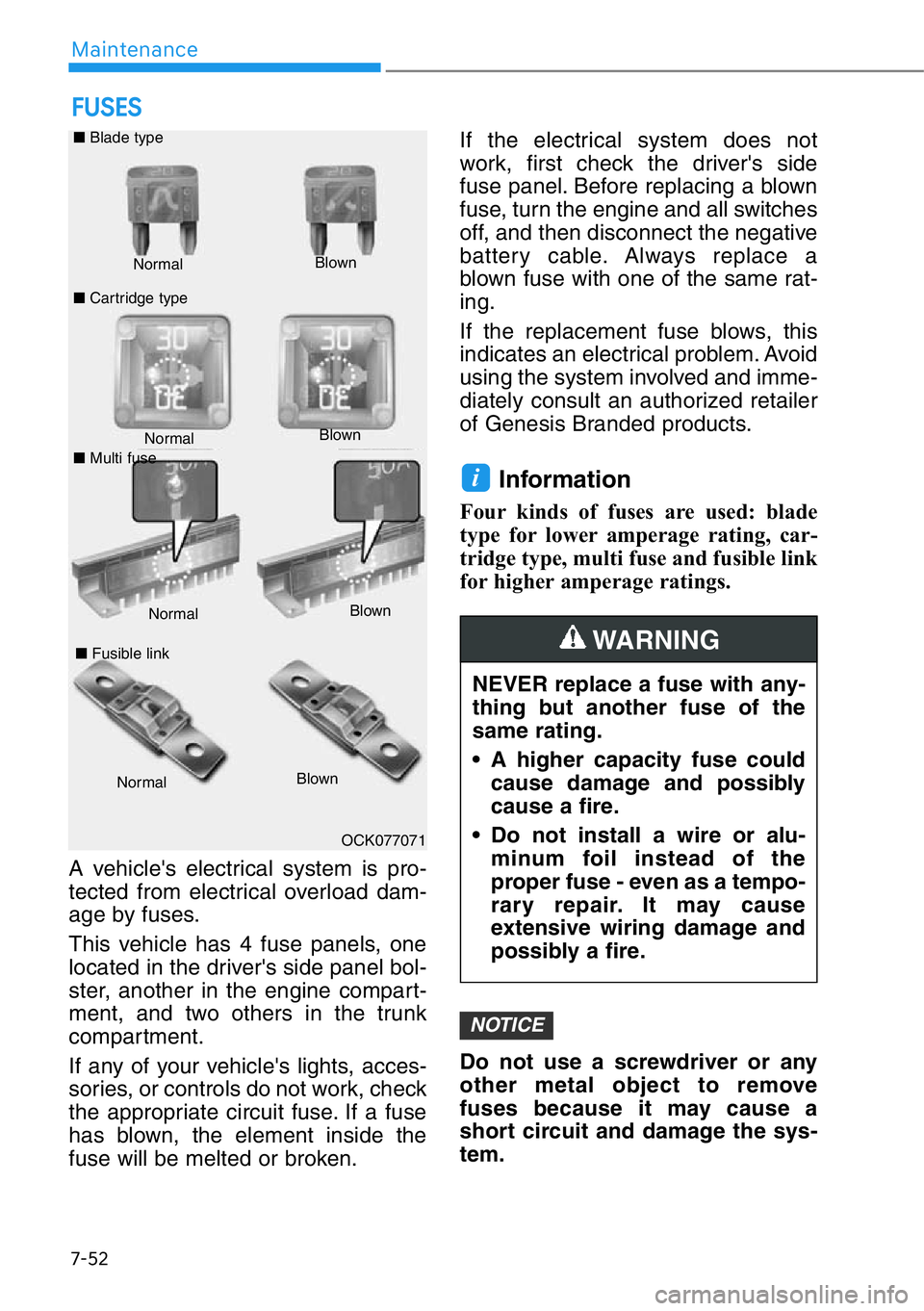
If any of your vehicle's lights, acces-
sories, or controls do not work, check
the appropriate circuit fuse. If a fuse
has blown, the element inside the
fuse will be melted or broken.If the electrical system does not
work, first check the driver's side
fuse panel. Before replacing a blown
fuse, turn the engine and all switches
off, and then disconnect the negative
battery cable. Always replace a
blown fuse with one of the same rat-
ing.
If the replacement fuse blows, this
indicates an electrical problem. Avoid
using the system involved and imme-
diately consult an authorized retailer
of Genesis Branded products.
Information
Four kinds of fuses are used: blade
type for lower amperage rating, car-
tridge type, multi fuse and fusible link
for higher amperage ratings.
Do not use a screwdriver or any
other metal object to remove
fuses because it may cause a
short circuit and damage the sys-
tem.
NOTICE
i
FUSES
Normal Normal ■Blade type
■Cartridge typeBlown
Blown
■Fusible link
NormalBlown
OCK077071
NEVER replace a fuse with any-
thing but another fuse of the
same rating.
• A higher capacity fuse could
cause damage and possibly
cause a fire.
• Do not install a wire or alu-
minum foil instead of the
proper fuse - even as a tempo-
rary repair. It may cause
extensive wiring damage and
possibly a fire.
WARNING
■Multi fuse
NormalBlown
Page 493 of 538
7-53
07
Instrument Panel Fuse
Replacement
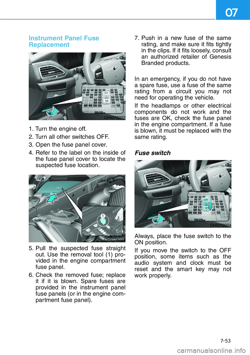
1. Turn the engine off.
2. Turn all other switches OFF.
3. Open the fuse panel cover.
4. Refer to the label on the inside of
the fuse panel cover to locate the
suspected fuse location.
5. Pull the suspected fuse straight
out. Use the removal tool (1) pro-
vided in the engine compartment
fuse panel.
6. Check the removed fuse; replace
it if it is blown. Spare fuses are
provided in the instrument panel
fuse panels (or in the engine com-
partment fuse panel).7. Push in a new fuse of the same
rating, and make sure it fits tightly
in the clips. If it fits loosely, consult
an authorized retailer of Genesis
Branded products.
In an emergency, if you do not have
a spare fuse, use a fuse of the same
rating from a circuit you may not
need for operating the vehicle.
If the headlamps or other electrical
components do not work and the
fuses are OK, check the fuse panel
in the engine compartment. If a fuse
is blown, it must be replaced with the
same rating.
Fuse switch
Always, place the fuse switch to the
ON position.
If you move the switch to the OFF
position, some items such as the
audio system and clock must be
reset and the smart key may not
work properly.
OHI078022
OHI078023
OHI078024
Page 494 of 538

7-54
Maintenance
Information
If the fuse switch is OFF, "Turn FUSE
SWITCH on" message will appear.
• Always place the fuse switch in
the ON position while driving the
vehicle.
• Do not move the fuse switch
repeatedly. The fuse switch may
be damaged.
Engine Compartment Panel
Fuse Replacement
1. Turn the engine off.
2. Turn all other switches OFF.
3. Remove the fuse panel cover by
pressing the tap and pulling up.
4. Check the removed fuse; replace
it if it is blown. To remove or insert
the fuse, use the fuse puller in the
engine compartment fuse panel.
5. Push in a new fuse of the same
rating, and make sure it fits tightly
in the clips. If it fits loosely, consult
an authorized retailer of Genesis
Branded products.
NOTICE
i
OHI078074LOHI078028
■Blade type fuse
OHI078029
■Cartridge type fuse
Page 495 of 538
7-55
07
After checking the fuse box in the
engine compartment securely
close the fuse box cover inside
the engine compartment, until it
clicks.
If the fuse box is not closed prop-
erly, water may leak in side, possi-
bly causing a malfunction with the
electrical system.
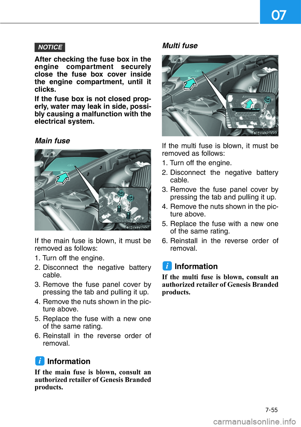
Main fuse
If the main fuse is blown, it must be
removed as follows:
1. Turn off the engine.
2. Disconnect the negative battery
cable.
3. Remove the fuse panel cover by
pressing the tab and pulling it up.
4. Remove the nuts shown in the pic-
ture above.
5. Replace the fuse with a new one
of the same rating.
6. Reinstall in the reverse order of
removal.
Information
If the main fuse is blown, consult an
authorized retailer of Genesis Branded
products.
Multi fuse
If the multi fuse is blown, it must be
removed as follows:
1. Turn off the engine.
2. Disconnect the negative battery
cable.
3. Remove the fuse panel cover by
pressing the tab and pulling it up.
4. Remove the nuts shown in the pic-
ture above.
5. Replace the fuse with a new one
of the same rating.
6. Reinstall in the reverse order of
removal.
Information
If the multi fuse is blown, consult an
authorized retailer of Genesis Branded
products.
i
i
NOTICE
OHI078026
OHI078027
Page 500 of 538
7-60
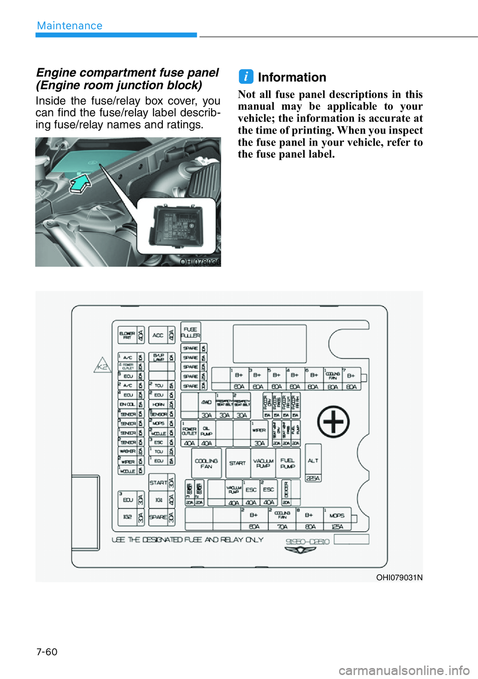
Maintenance
Engine compartment fuse panel
(Engine room junction block)
Inside the fuse/relay box cover, you
can find the fuse/relay label describ-
ing fuse/relay names and ratings.
Information
Not all fuse panel descriptions in this
manual may be applicable to your
vehicle; the information is accurate at
the time of printing. When you inspect
the fuse panel in your vehicle, refer to
the fuse panel label.
i
OHI079031N
OHI078030
Page 501 of 538

7-61
07
Engine compartment fuse panel
Fuse name Fuse rating Circuit protected
ALT 200A
Alternator, Multifuse (BATT) - B+7, COOLING FAN1, B+6,
B+5, B+4, B+3, B+1, (Fuse - WIPER1, FUEL PUMP,
POWER OUTLET1, 4WD, PRESAFETY SEAT BELT1, PRE-
SAFETY SEAT BELT2, P/DOOR DRV, P/DOOR PASS,
P/DOOR RR LH, P/DOOR RR RH, SEAT VENT DRV, SEAT
VENT PASS)
B+1 60AIGPM (Fuse - BRAKE SWITCH, MODULE14, MODULE15,
Leak Current Autocut Device) (Fuse - ROOM LAMP, MEMO-
RY1, MULTI MEDIA1, MULTI MEDIA2, MULTI MEDIA3)
B+3 60AIGPM (IPS2/IPS3, Fuse - MODULE3, E-SHIFTER1)
B+5 60AIGPM (Fuse - P/SEAT (RR LH) 2, P/SEAT (DRV) 2, P/WIN-
DOW (RH), SUNROOF, P/SEAT (PASS) 2, P/SEAT (RR LH) 1)
B+460AIGPM (IPS4/IPS8/IPS9/IPS10, Fuse - IBU1, IBU2, MOD-
ULE12)
B+6 60AMetal Core Block (PCB #1 Fuse - ECU3, IG2, MODULE1)
B+780AMetal Core Block (PCB #2 Fuse - ACC, B/UP LAMP, HORN)
B+2 60AIGPM (Fuse - P/SEAT (DRV) 1, P/SEAT (PASS) 1, P/WIN-
DOW LH, CURTAIN, POWER HANDLE)
B+8 80AMetal Core Block (PCB #1 Fuse - BLOWER FRT, POWER
OUTLET4, A/C2)
MDPS1125AMDPS Unit
POWER
OUTLET3 20AFront Power Outlet & Cigarette Lighter
POWER
OUTLET2 20AFront Power Outlet & Cigarette Lighter
VACUUM
PUMP 40A[3.3 T-GDI] Vacuum Pump Relay
ESC1 40AESC Control Module, Multipurpose Check Connector
ESC2 40AESC Control Module, Multipurpose Check Connector
DEICER 20A Front Deicer Relay