cooling GENESIS GV80 2021 User Guide
[x] Cancel search | Manufacturer: GENESIS, Model Year: 2021, Model line: GV80, Model: GENESIS GV80 2021Pages: 632, PDF Size: 9.37 MB
Page 554 of 632

09
9-13
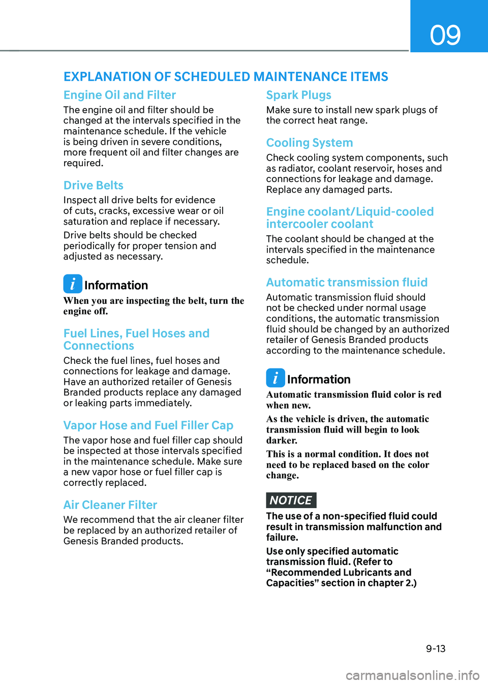
Engine Oil and Filter
The engine oil and filter should be
changed at the intervals specified in the
maintenance schedule. If the vehicle
is being driven in severe conditions,
more frequent oil and filter changes are
required.
Drive Belts
Inspect all drive belts for evidence
of cuts, cracks, excessive wear or oil
saturation and replace if necessary.
Drive belts should be checked
periodically for proper tension and
adjusted as necessary.
Information
When you are inspecting the belt, turn the
engine off.
Fuel Lines, Fuel Hoses and
Connections
Check the fuel lines, fuel hoses and
connections for leakage and damage.
Have an authorized retailer of Genesis
Branded products replace any damaged
or leaking parts immediately.
Vapor Hose and Fuel Filler Cap
The vapor hose and fuel filler cap should
be inspected at those intervals specified
in the maintenance schedule. Make sure
a new vapor hose or fuel filler cap is
correctly replaced.
Air Cleaner Filter
We recommend that the air cleaner filter
be replaced by an authorized retailer of
Genesis Branded products.
Spark Plugs
Make sure to install new spark plugs of
the correct heat range.
Cooling System
Check cooling system components, such
as radiator, coolant reservoir, hoses and
connections for leakage and damage.
Replace any damaged parts.
Engine coolant/Liquid-cooled
intercooler coolant
The coolant should be changed at the
intervals specified in the maintenance
schedule.
Automatic transmission fluid
Automatic transmission fluid should
not be checked under normal usage
conditions, the automatic transmission
fluid should be changed by an authorized
retailer of Genesis Branded products
according to the maintenance schedule.
Information
Automatic transmission fluid color is red
when new.
As the vehicle is driven, the automatic
transmission fluid will begin to look
darker.
This is a normal condition. It does not
need to be replaced based on the color
change.
NOTICE
The use of a non-specified fluid could
result in transmission malfunction and
failure.
Use only specified automatic
transmission fluid. (Refer to
“Recommended Lubricants and
Capacities” section in chapter 2.)
EXPLANATION OF SCHEDULED MAINTENANCE ITEMS
Page 558 of 632

09
9-17
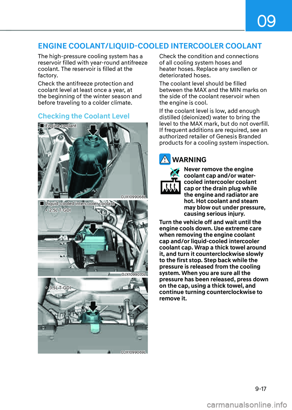
ENGINE COOLANT/LIQUID-COOLED INTERCOOLER COOLANT
The high-pressure cooling system has a
reservoir filled with year-round antifreeze
coolant. The reservoir is filled at the
factory.
Check the antifreeze protection and
coolant level at least once a year, at
the beginning of the winter season and
before traveling to a colder climate.
Checking the Coolant Level
�
Page 559 of 632

Maintenance9-18
Information
The coolant level is influenced by the
engine temperature. Before checking or
refilling the coolant, turn the engine off.
WARNING
The electric motor for the cooling fan may continue to
operate or start up when the
engine is not running and can
cause serious injury. Keep
hands, clothing and tools away
from the rotating fan blades of
the cooling fan.
Always turn off the vehicle unless the
vehicle has to be inspected with the
engine on. Be cautious as the cooling
fan may operate if the negative (-)
battery terminal is not disconnected.
WARNING
Make sure the coolant cap is properly
closed after refilling coolant. Otherwise
the engine could be overheated while
driving.
�
Page 593 of 632

Maintenance
9-52
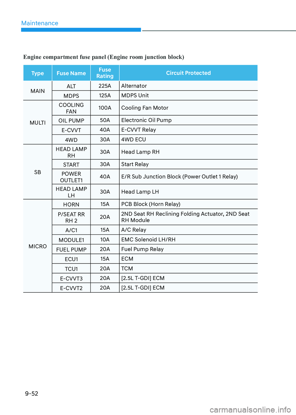
Engine compartment fuse panel (Engine room junction block)
TypeFuse Name Fuse
Rating Circuit Protected
MAIN A LT
225A
Alternator
MDPS 125A
MDPS Unit
MULTI COOLING
FAN 100A
Cooling Fan Motor
OIL PUMP 50A
Electronic Oil Pump
E-CVVT 40A
E-CVVT Relay
4WD 30A
4WD ECU
SB HEAD LAMP
RH 30A
Head Lamp RH
START 30A
Start Relay
POWER
OUTLET1 40A
E/R Sub Junction Block (Power Outlet 1 Relay)
HEAD LAMP LH 30A
Head Lamp LH
MICRO HORN
15A
PCB Block (Horn Relay)
P/SEAT RR RH 2 20A
2ND Seat RH Reclining Folding Actuator, 2ND Seat
RH Module
A/C1 15A
A/C Relay
MODULE1 10A
Solenoid LH/RH
FUEL PUMP 20A
Fuel Pump Relay
ECU1 15A
ECM
TCU1 20A
TCM
E-CVVT3 20A
[2.5L T-GDI] ECM
E-CVVT2 20A
[2.5L T-GDI] ECM
Page 594 of 632

09
9-53
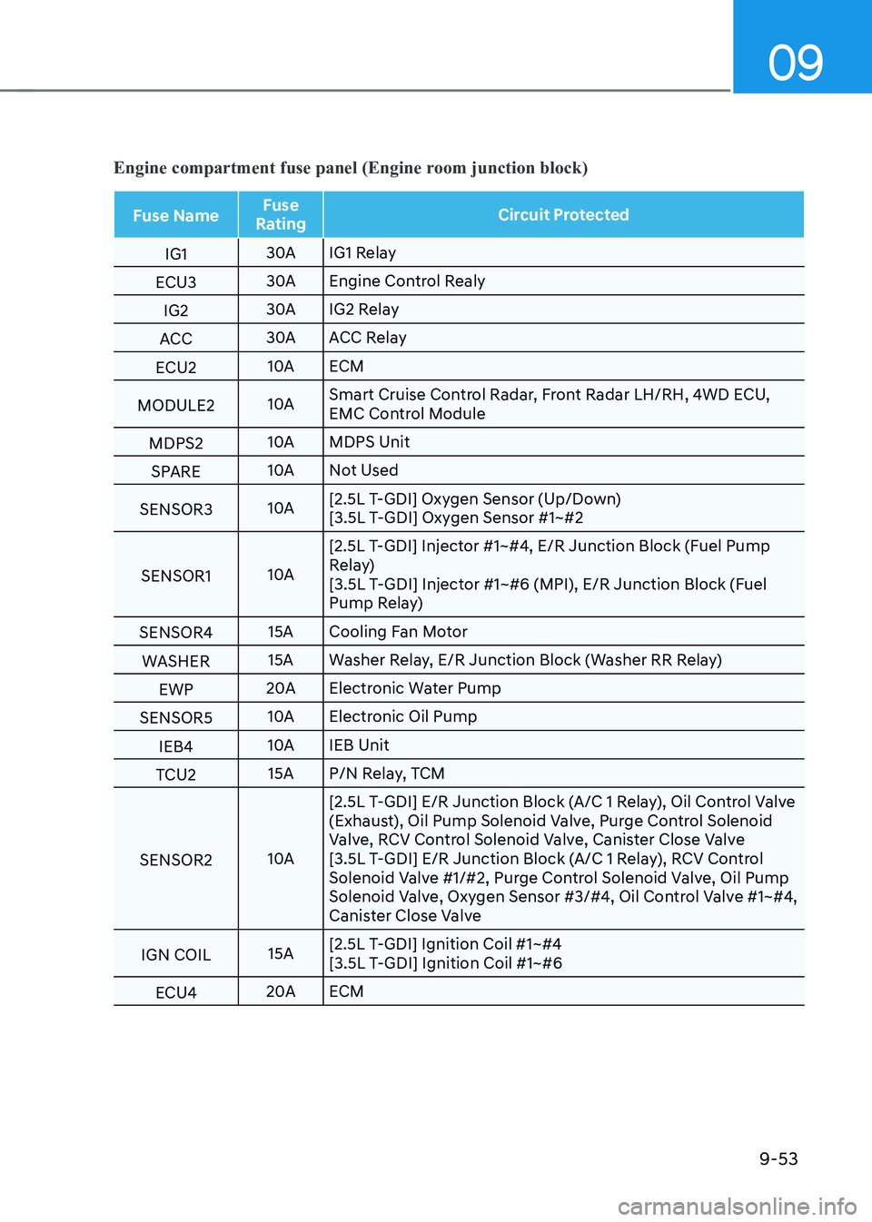
Engine compartment fuse panel (Engine room junction block)
Fuse NameFuse
Rating Circuit Protected
IG1 30A
IG1 Relay
ECU3 30A
Engine Control Realy
IG2 30A
IG2 Relay
ACC 30A
ACC Relay
ECU2 10A
ECM
MODULE2 10ASmart Cruise Control Radar, Front Radar LH/RH, 4WD ECU,
Control Module
MDPS2 10A
MDPS Unit
SPARE 10A
Not Used
SENSOR3 10A[2.5L T-GDI] Oxygen Sensor (Up/Down)
[3.5L T-GDI] Oxygen Sensor #1~#2
SENSOR1 10A[2.5L T-GDI] Injector #1~#4, E/R Junction Block (Fuel Pump
Relay)
[3.5L T-GDI] Injector #1~#6 (MPI), E/R Junction Block (Fuel
Pump Relay)
SENSOR4 15A
Cooling Fan Motor
WASHER 15A
Washer Relay, E/R Junction Block (Washer RR Relay)
EWP 20A
Electronic Water Pump
SENSOR5 10A
Electronic Oil Pump
IEB4 10A
IEB Unit
TCU2 15A
P/N Relay, TCM
SENSOR2 10A[2.5L T-GDI] E/R Junction Block (A/C 1 Relay), Oil Control Valve
(Exhaust), Oil Pump Solenoid Valve, Purge Control Solenoid
Valve, RCV Control Solenoid Valve, Canister Close Valve
[3.5L T-GDI] E/R Junction Block (A/C 1 Relay), RCV Control
Solenoid Valve #1/#2, Purge Control Solenoid Valve, Oil Pump
Solenoid Valve, Oxygen Sensor #3/#4, Oil Control Valve #1~#4,
Canister Close Valve
IGN COIL 15A[2.5L T-GDI] Ignition Coil #1~#4
[3.5L T-GDI] Ignition Coil #1~#6
ECU4 20A
ECM