navigation GENESIS GV80 2021 User Guide
[x] Cancel search | Manufacturer: GENESIS, Model Year: 2021, Model line: GV80, Model: GENESIS GV80 2021Pages: 632, PDF Size: 9.37 MB
Page 440 of 632
![GENESIS GV80 2021 User Guide Driver Assistance System
7-92
OJX1070280LOJX1070280L[1] : Set route, [2] : Branch line, [3] : Driving route,
[4] : Main road, [5] : Curved road section
• When there is a difference between
the nav GENESIS GV80 2021 User Guide Driver Assistance System
7-92
OJX1070280LOJX1070280L[1] : Set route, [2] : Branch line, [3] : Driving route,
[4] : Main road, [5] : Curved road section
• When there is a difference between
the nav](/img/46/35616/w960_35616-439.png)
Driver Assistance System
7-92
OJX1070280LOJX1070280L[1] : Set route, [2] : Branch line, [3] : Driving route,
[4] : Main road, [5] : Curved road section
• When there is a difference between
the navigation set route (branch line)
and the driving route (main road),
Highway Curve Zone Auto Slowdown
function may not operate until the
driving route is recognized as the
main road.
• When the vehicle's driving route
is recognized as the main road by
maintaining the main road instead
of the navigation set route, Highway
Curve Zone Auto Slowdown function
will operate. Depending on the
distance to the curve and the current
vehicle speed, vehicle deceleration
may not be sufficient or may
decelerate rapidly.
OJX1070281LOJX1070281L[1] : Set route, [2] : Branch line, [3] : Driving route,
[4] : Main road, [5] : Curved road section
• When there is a difference between
the navigation route (main road)
and the driving route (branch line),
Highway Curve Zone Auto Slowdown
function will operate based on the
curve information on the main road.
• When it is judged that you are driving
out of the route by entering the
highway interchange or junction,
Highway Curve Zone Auto Slowdown
function will not operate.
Page 441 of 632
![GENESIS GV80 2021 User Guide 07
7-93
OJX1070282LOJX1070282L[1] : Driving route, [2] : Branch line,
[3] : Curved road section, [4] : Main road
• If there is no destination set on the
navigation, Highway Curve Zone Auto
Slowdow GENESIS GV80 2021 User Guide 07
7-93
OJX1070282LOJX1070282L[1] : Driving route, [2] : Branch line,
[3] : Curved road section, [4] : Main road
• If there is no destination set on the
navigation, Highway Curve Zone Auto
Slowdow](/img/46/35616/w960_35616-440.png)
07
7-93
OJX1070282LOJX1070282L[1] : Driving route, [2] : Branch line,
[3] : Curved road section, [4] : Main road
• If there is no destination set on the
navigation, Highway Curve Zone Auto
Slowdown function will operate based
on the curve information on the main
road.
• Even if you depart from the main road,
Highway Curve Zone Auto Slowdown
function may temporarily operate
due to navigation information of the
highway curve section.
WARNING
• Navigation-based Smart Cruise
Control is not a substitute for safe
driving practices, but a convenience
function. Always have your eyes on
the road, and it is the responsibility
of the driver to avoid violating traffic
laws.
• The navigation’s speed limit
information may differ from the
actual speed limit information on the
road. It is the driver's responsibility
to check the speed limit on the
actual driving road or lane.
• Navigation-based Smart Cruise
Control may not operate due to the
existence of leading vehicles and
the driving conditions of the vehicle.
Always pay attention to road and
driving conditions while driving.
• When you are towing a trailer or
another vehicle, we recommend
that Navigation-based Smart Cruise
Control is turned off due to safety
reasons.
• After you pass through a tollgate on a
highway (or motorway), Navigation-
based Smart Cruise Control will
operate based on the first lane. If
you enter one of the other lanes, the
system may not operate properly.
Page 442 of 632
Driver Assistance System
7-94
• The vehicle will accelerate if the
driver depresses the accelerator
pedal while Navigation-based Smart
Cruise Control is operating, and
the system will not decelerate the
vehicle.
• If the driver accelerates and
releases the accelerator pedal while
Navigation-based Smart Cruise
Control is operating, the vehicle may
not decelerate sufficiently or may
rapidly decelerate to a safe speed.
• If the curve is too large or too small,
Navigation-based Smart Cruise
Control may not operate.
• Navigation-based Smart Cruise
Control will automatically be
cancelled when you leave the
highway (or motorway) main road.
Always pay attention to road and
driving conditions while driving.
Information
• The speed information on the cluster
and navigation may differ.
• The time gap could occur between
the navigation’s guidance and when
Navigation-based Smart Cruise Control
operation starts and ends.
• Even if you are driving at a speed lower
than Smart Cruise Control set speed,
acceleration may be limited by the
curve sections ahead.
• If Navigation-based Smart Cruise
Control is operating while leaving the
main road to enter an interchange,
junction, rest area, etc., the system may
operate for a certain period of time.
• Deceleration by Navigation-based
Smart Cruise Control may feel it is not
sufficient due to road conditions such
as uneven road surfaces, narrow lanes,
etc.
Information
This device complies with Part 15 of the FCC
rules.
Operation is subject to the following three
conditions:
1. This device may not cause harmful
interference, and
2. This device must accept any
interference received, including
interference that may cause undesired
operation.
3. Changes or modifications not expressly
approved by the party responsible
for compliance could void the user's
authority to operate the device.
Information
Radio frequency radiation exposure
information:
This equipment complies with FCC radiation
exposure limits set forth for an uncontrolled
environment.
This equipment should be installed and
operated with minimum distance of 8 in. (20
cm) between the radiator (antenna) and your
body.
This transmitter must not be co-located or
operating in conjunction with any other
antenna or transmitter.
Page 447 of 632

07
7-99
HIGHWAY DRIVING ASSIST (HDA) (IF EQUIPPED)
Basic function
Highway Driving Assist is designed to
help detect vehicles and lanes ahead,
and help maintain distance from the
vehicle ahead, maintain the set speed,
and help center the vehicle in the lane
while driving on the highway.
OADAS035OADAS035
Highway Lane Change Assist (if equipped)
Highway Lane Change Assist function
helps change lanes to the direction the
driver slightly moves the turn signal
switch if the system determines that a
lane change is possible.
OADAS036OADAS036
Information
• Highway Driving Assist is available
only on controlled access road of
certain highways.
ÃControlled access road indicates
roads with limited entrances and exits
that allow uninterrupted high speed
traffic flow. Only passenger cars and
motorcycles are allowed on controlled
access roads.
Available highway (Controlled access road)
USA Select Interstate Highway
and U.S. (Federal) and State Highways
Canada Select Provincial and Territorial
Highways
• Additional highways may be expanded
by future navigation updates.
Page 456 of 632

Driver Assistance System
7-108
• Always have your eyes on the road,
and it is the responsibility of the
driver to avoid violating traffic laws.
The vehicle manufacturer is not
responsible for any traffic violation
or accidents caused by the driver.
• Highway Driving Assist may not
be able to recognize all traffic
situations. The system may not
detect possible collisions due to
limitations of the system. Always
be aware of the limitations of the
system. Obstacles such as vehicles,
motorcycles, bicycles, pedestrians,
unspecified objects, structures, etc.
that may collide with the vehicle may
not be detected.
• Highway Driving Assist will turn off
automatically under the following
situations:
-Driving on roads that the system
does not operate, such as a rest
area, intersection, junction, etc.
-The navigation does not operate
properly such as when the
navigation is being updated or
restarted
• Highway Driving Assist may
inadvertently operate or turn off
depending on road conditions
(navigation information) and
surroundings.
• Lane Following Assist function may
be temporarily disabled when the
front view camera cannot detect
lanes properly or the hands-off
warning is on.
• You may not hear the warning sound
of Highway Driving Assist if the
surrounding is noisy.
• If the vehicle is driven at high speed
above a certain speed at a curve,
your vehicle may drive to one side or
may depart from the driving lane.
• When you are towing a trailer or
another vehicle, we recommend that
Highway Driving Assist is turned off
due to safety reasons.
• The hands–off warning message
may appear early or late depending
on how the steering wheel is held or
road conditions. Always have your
hands on the steering wheel while
driving.
• For your safety, please read the
owner's manual before using the
Highway Driving Assist.
• Highway Driving Assist will not
operate when the engine is started,
or when the detecting sensors or
navigation is being initialized.
Page 457 of 632
07
7-109
Limitations of the system
Highway Driving Assist and Highway
Lane Change function may not operate
normally, or may not operate under the
following circumstances:
• The map information and the
actual road is different because the
navigation is not updated
• The map information and the actual
road is different because of real-time
GPS data or map information error
• The infotainment system is overloaded
by simultaneously performing
functions such as route search, video
playback, voice recognition, etc.
• GPS signals are blocked in areas such
as a tunnel
• The driver goes off course or the
route to the destination is changed or
canceled by resetting the navigation
• The vehicle enters a service station or
rest area
• Android Auto or Car Play is operating
• The navigation cannot detect the
current vehicle position (ex: elevated
roads including overpass adjacent to
general roads or nearby roads exist in
a parallel way)
• White single dotted lane line or road
edge cannot be detected
• The road is temporarily controlled due
to construction, etc.
• There is no structure, such as a
medium strip, guardrails, etc., on the
road
• There is a changeable lane in the
direction of lane change
For more details on the limitations of
the front view camera, front radar, front
corner radar and rear corner radar, refer
to “Forward Collision-Avoidance Assist
(FCA)” section in chapter 7.
Information
This device complies with Part 15 of the
FCC rules.
Operation is subject to the following three
conditions:
1. This device may not cause harmful
interference, and
2. This device must accept any
interference received, including
interference that may cause undesired
operation.
3. Changes or modifications not expressly
approved by the party responsible
for compliance could void the user's
authority to operate the device.
Information
Radio frequency radiation exposure
information:
This equipment complies with FCC
radiation exposure limits set forth for an
uncontrolled environment.
This equipment should be installed and
operated with minimum distance of 8 in.
(20 cm) between the radiator (antenna)
and your body.
This transmitter must not be co-located or
operating in conjunction with any other
antenna or transmitter.
Page 522 of 632

08
8-11
TPMS (Tire Pressure
Monitoring System)
Malfunction Indicator
The TPMS Malfunction Indicator
will illuminate after it blinks for
approximately one minute when there
is a problem with the Tire Pressure
Monitoring System.
Have the system checked by an
authorized retailer of Genesis Branded
products as soon as possible.
NOTICE
If there is a malfunction with the TPMS,
the Low Tire Pressure Position Telltale
will not be displayed even though the
vehicle has an under-inflated tire.
NOTICE
The TPMS Malfunction Indicator may
illuminate after blinking for one minute
if the vehicle is near electric power
supply cables or radio transmitters
such as police stations, government
and public offices, broadcasting
stations, military installations, airports,
transmitting towers, etc.
Additionally, the TPMS Malfunction
Indicator may illuminate if snow chains
are used or electronic devices such as
computers, chargers, remote starters,
navigation, etc. This may interfere with
normal operation of the TPMS.
Changing a Tire with TPMS
If you have a flat tire, the Low Tire
Pressure and Position telltales will come
on. Have the flat tire repaired by an
authorized retailer of Genesis Branded
products as soon as possible or replace
the flat tire with the spare tire.
NOTICE
It is recommended that you do not use a
puncture-repairing agent not approved
by an authorized retailer of Genesis
Branded products to repair and/or
inflate a low pressure tire. Tire sealant
not approved by an authorized retailer
of Genesis Branded products may
damage the tire pressure sensor.
The spare tire does not come with a
tire pressure monitoring sensor. When
the low pressure tire or the flat tire is
replaced with the spare tire, the Low
Tire Pressure LCD position indicator will
remain on. Also, the TPMS Malfunction
Indicator will illuminate after blinking
for one minute if the vehicle is driven
at speed above 15.5 mph (25 km/h) for
approximately 20 minutes.
Once the original wheel equipped with
a tire pressure monitoring sensor is
reinflated to the recommended pressure
and reinstalled on the vehicle, the
Low Tire Pressure Telltale and TPMS
Malfunction Indicator will go off within a
few minutes of driving.
Page 589 of 632
Maintenance
9-48
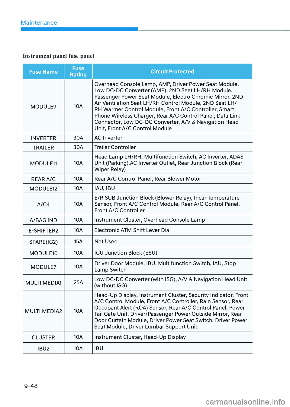
Instrument panel fuse panel
Fuse NameFuse
Rating Circuit Protected
MODULE9 10AOverhead Console Lamp, AMP, Driver Power Seat Module,
Low DC-DC Converter (AMP), 2ND Seat LH/RH Module,
Passenger Power Seat Module, Electro Chromic Mirror, 2ND
Air Ventilation Seat LH/RH Control Module, 2ND Seat LH/
RH Warmer Control Module, Front A/C Controller, Smart
Phone Wireless Charger, Rear A/C Control Panel, Data Link
Connector, Low DC-DC Converter, A/V & Navigation Head
Unit, Front A/C Control Module
INVERTER 30A
AC Inverter
TRAILER 30A
Trailer Controller
MODULE11 10AHead Lamp LH/RH, Multifunction Switch, AC Inverter, ADAS
Unit (Parking),AC Inverter Outlet, Rear Junction Block (Rear
Wiper Relay)
REAR A/C 10A
Rear A/C Control Panel, Rear Blower Motor
MODULE12 10A
IAU, IBU
A/C4 10AE/R SUB Junction Block (Blower Relay), Incar Temperature
Sensor, Front A/C Control Module, Rear A/C Control Panel,
Front A/C Controller
A/BAG IND 10A
Instrument Cluster, Overhead Console Lamp
E-SHIFTER2 10A
Electronic ATM Shift Lever Dial
SPARE(IG2) 15A
Not Used
MODULE10 10A
ICU Junction Block (ESU)
MODULE7 10ADriver Door Module, IBU, Multifunction Switch, IAU, Stop
Lamp Switch
MULTI MEDIA1 25ALow DC-DC Converter (with ISG), A/V & Navigation Head Unit
(without ISG)
MULTI MEDIA2 10AHead-Up Display, Instrument Cluster, Security Indicator, Front
A/C Control Module, Front A/C Controller, Rain Sensor, Rear
Occupant Alert (ROA) Sensor, Rear A/C Control Panel, Power
Tail Gate Unit, Driver/Passenger Power Outside Mirror, Rear
Door Curtain Module, Driver Power Seat Switch, Driver Power
Seat Module, Driver Lumbar Support Unit
CLUSTER 10A
Instrument Cluster, Head-Up Display
IBU2 10A
IBU
Page 590 of 632
09
9-49
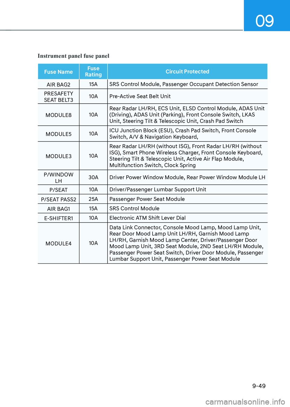
Instrument panel fuse panel
Fuse NameFuse
Rating Circuit Protected
AIR BAG2 15A
SRS Control Module, Passenger Occupant Detection Sensor
PRESAFETY
SEAT BELT3 10A
Pre-Active Seat Belt Unit
MODULE8 10ARear Radar LH/RH, ECS Unit, ELSD Control Module, ADAS Unit
(Driving), ADAS Unit (Parking), Front Console Switch, LKAS
Unit, Steering Tilt & Telescopic Unit, Crash Pad Switch
MODULE5 10AICU Junction Block (ESU), Crash Pad Switch, Front Console
Switch, A/V & Navigation Keyboard,
MODULE3 10ARear Radar LH/RH (without ISG), Front Radar LH/RH (without
ISG), Smart Phone Wireless Charger, Front Console Keyboard,
Steering Tilt & Telescopic Unit, Active Air Flap Module,
Multifunction Switch, Clock Spring
P/WINDOW LH 30A
Driver Power Window Module, Rear Power Window Module LH
P/SEAT 10A
Driver/Passenger Lumbar Support Unit
P/SEAT PASS2 25A
Passenger Power Seat Module
AIR BAG1 15A
SRS Control Module
E-SHIFTER1 10A
Electronic ATM Shift Lever Dial
MODULE4 10AData Link Connector, Console Mood Lamp, Mood Lamp Unit,
Rear Door Mood Lamp Unit LH/RH, Garnish Mood Lamp
LH/RH, Garnish Mood Lamp Center, Driver/Passenger Door
Mood Lamp Unit, 3RD Seat Module, 2ND Seat LH/RH Module,
Passenger Power Seat Switch, Driver Door Module, Passenger
Lumbar Support Unit, Passenger Power Seat Module
Page 591 of 632
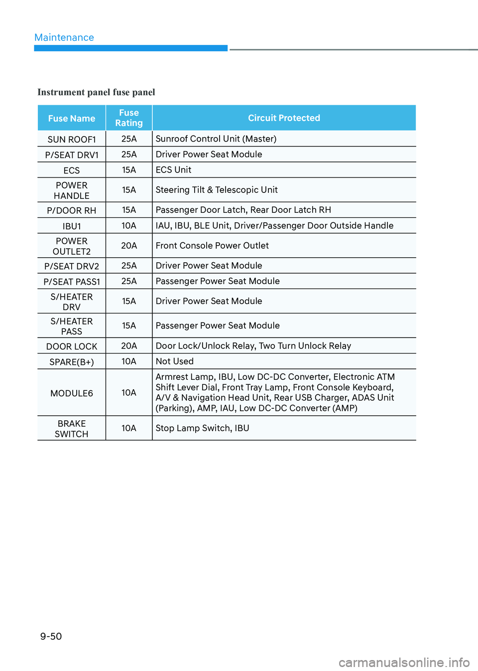
Maintenance
9-50
Instrument panel fuse panel
Fuse NameFuse
Rating Circuit Protected
SUN ROOF1 25A
Sunroof Control Unit (Master)
P/SEAT DRV1 25A
Driver Power Seat Module
ECS 15A
ECS Unit
POWER
HANDLE 15A
Steering Tilt & Telescopic Unit
P/DOOR RH 15A
Passenger Door Latch, Rear Door Latch RH
IBU1 10A
IAU, IBU, BLE Unit, Driver/Passenger Door Outside Handle
POWER
OUTLET2 20A
Front Console Power Outlet
P/SEAT DRV2 25A
Driver Power Seat Module
P/SEAT PASS1 25A
Passenger Power Seat Module
S/HEATER DRV 15A
Driver Power Seat Module
S/HEATER PASS 15A
Passenger Power Seat Module
DOOR LOCK 20A
Door Lock/Unlock Relay, Two Turn Unlock Relay
SPARE(B+) 10A
Not Used
MODULE6 10AArmrest Lamp, IBU, Low DC-DC Converter, Electronic ATM
Shift Lever Dial, Front Tray Lamp, Front Console Keyboard,
A/V & Navigation Head Unit, Rear USB Charger, ADAS Unit
(Parking), AMP, IAU, Low DC-DC Converter (AMP)
BRAKE
SWITCH 10A
Stop Lamp Switch, IBU