temperature GMC ACADIA 2021 Owner's Manual
[x] Cancel search | Manufacturer: GMC, Model Year: 2021, Model line: ACADIA, Model: GMC ACADIA 2021Pages: 396, PDF Size: 7.87 MB
Page 3 of 396
GMC Acadia/Acadia Denali Owner Manual (GMNA-Localizing-U.S./Canada/
Mexico-14608671) - 2021 - CRC - 10/26/20
2 Introduction
Using this Manual
To quickly locate information about the
vehicle, use the Index in the back of the
manual. It is an alphabetical list of what is
in the manual and the page number where
it can be found.
Danger, Warning, and Caution
Warning messages found on vehicle labels
and in this manual describe hazards and
what to do to avoid or reduce them.
{Danger
Danger indicates a hazard with a high
level of risk which will result in serious
injury or death.
{Warning
Warning indicates a hazard that could
result in injury or death.
Caution
Caution indicates a hazard that could
result in property or vehicle damage.
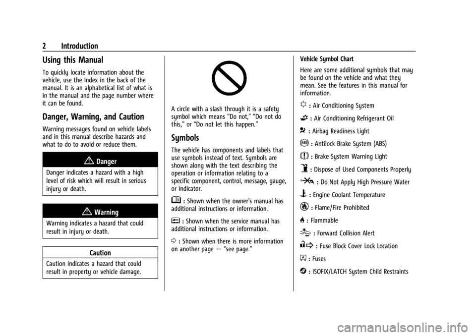
A circle with a slash through it is a safety
symbol which means“Do not,” “Do not do
this,” or“Do not let this happen.”
Symbols
The vehicle has components and labels that
use symbols instead of text. Symbols are
shown along with the text describing the
operation or information relating to a
specific component, control, message, gauge,
or indicator.
M:Shown when the owner’s manual has
additional instructions or information.
*: Shown when the service manual has
additional instructions or information.
0: Shown when there is more information
on another page — “see page.” Vehicle Symbol Chart
Here are some additional symbols that may
be found on the vehicle and what they
mean. See the features in this manual for
information.
u:
Air Conditioning System
G:Air Conditioning Refrigerant Oil
9:Airbag Readiness Light
!:Antilock Brake System (ABS)
$:Brake System Warning Light
9:Dispose of Used Components Properly
P:Do Not Apply High Pressure Water
B:Engine Coolant Temperature
_:Flame/Fire Prohibited
H: Flammable
[:Forward Collision Alert
R:Fuse Block Cover Lock Location
+:Fuses
j:ISOFIX/LATCH System Child Restraints
Page 13 of 396
GMC Acadia/Acadia Denali Owner Manual (GMNA-Localizing-U.S./Canada/
Mexico-14608671) - 2021 - CRC - 10/26/20
12 Keys, Doors, and Windows
To program additional transmitters,
repeat Steps 4–6.
When all additional transmitters are
programmed, press and hold ENGINE
START/STOP for 12 seconds to exit
programming mode.
7. Put the key back into the transmitter.
8. Replace the key lock cylinder cap. See Door Locks 015.
Starting the Vehicle with a Low
Transmitter Battery
When the vehicle is started, if the
transmitter battery is weak, the DIC may
display NO REMOTE DETECTED or NO
REMOTE KEY WAS DETECTED PLACE KEY IN
TRANSMITTER POCKET THEN START YOUR
VEHICLE. The DIC may also display REPLACE
BATTERY IN REMOTE KEY.
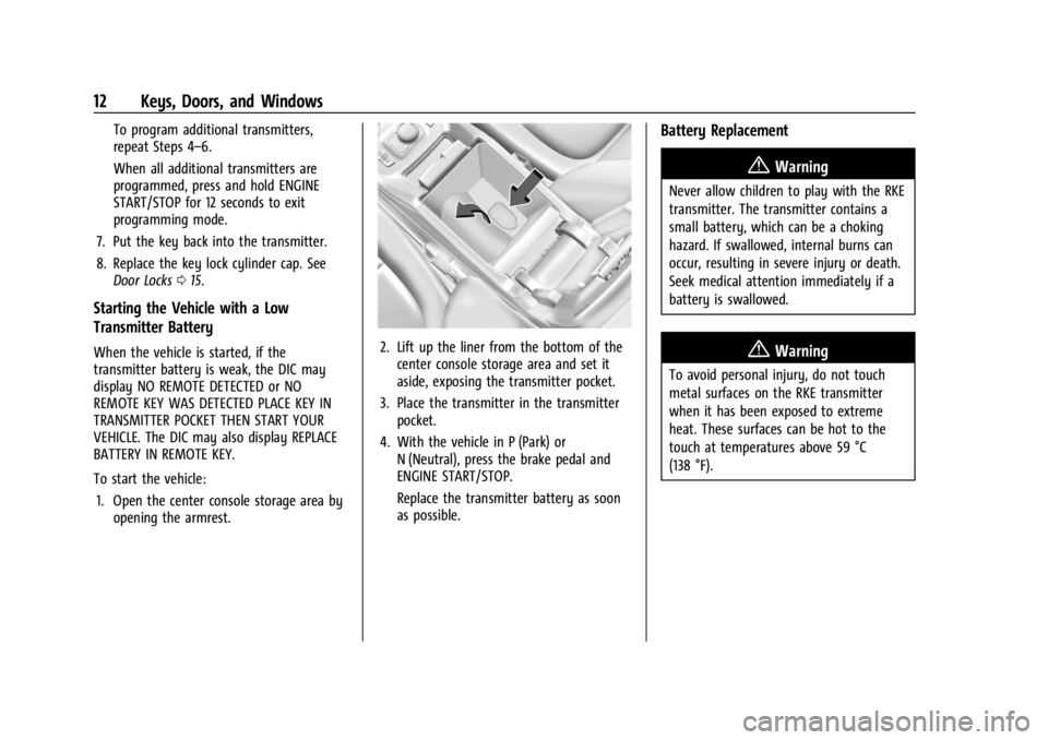
To start the vehicle:
1. Open the center console storage area by opening the armrest.2. Lift up the liner from the bottom of thecenter console storage area and set it
aside, exposing the transmitter pocket.
3. Place the transmitter in the transmitter pocket.
4. With the vehicle in P (Park) or N (Neutral), press the brake pedal and
ENGINE START/STOP.
Replace the transmitter battery as soon
as possible.
Battery Replacement
{Warning
Never allow children to play with the RKE
transmitter. The transmitter contains a
small battery, which can be a choking
hazard. If swallowed, internal burns can
occur, resulting in severe injury or death.
Seek medical attention immediately if a
battery is swallowed.
{Warning
To avoid personal injury, do not touch
metal surfaces on the RKE transmitter
when it has been exposed to extreme
heat. These surfaces can be hot to the
touch at temperatures above 59 °C
(138 °F).
Page 14 of 396
GMC Acadia/Acadia Denali Owner Manual (GMNA-Localizing-U.S./Canada/
Mexico-14608671) - 2021 - CRC - 10/26/20
Keys, Doors, and Windows 13
Caution
When replacing the battery, do not touch
any of the circuitry on the transmitter.
Static from your body could damage the
transmitter.
Caution
Always replace the battery with the
correct type. Replacing the battery with
an incorrect type could potentially create
a risk of battery explosion. Dispose of
used batteries according to instructions
and local laws. Do not attempt to burn,
crush, or cut the used battery, and avoid
exposing the battery to environments
with extremely low air pressures or high
temperatures.
Replace the battery in the transmitter soon
if the DIC displays REPLACE BATTERY IN
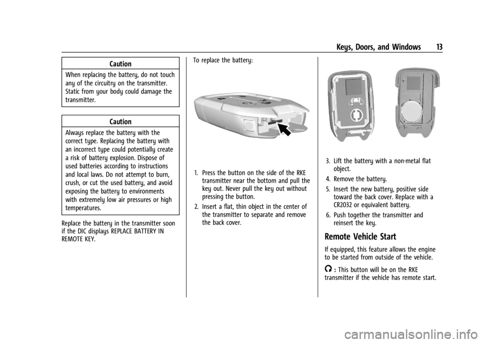
REMOTE KEY. To replace the battery:
1. Press the button on the side of the RKE
transmitter near the bottom and pull the
key out. Never pull the key out without
pressing the button.
2. Insert a flat, thin object in the center of the transmitter to separate and remove
the back cover.
3. Lift the battery with a non-metal flatobject.
4. Remove the battery.
5. Insert the new battery, positive side toward the back cover. Replace with a
CR2032 or equivalent battery.
6. Push together the transmitter and reinsert the key.
Remote Vehicle Start
If equipped, this feature allows the engine
to be started from outside of the vehicle.
/:This button will be on the RKE
transmitter if the vehicle has remote start.
Page 16 of 396
GMC Acadia/Acadia Denali Owner Manual (GMNA-Localizing-U.S./Canada/
Mexico-14608671) - 2021 - CRC - 10/26/20
Keys, Doors, and Windows 15
.The engine coolant temperature is
too high.
.The oil pressure is low.
.Two remote vehicle starts or a start with
an extension have already been used.
.The vehicle is not in P (Park).
Door Locks
{Warning
Unlocked doors can be dangerous.
.Passengers, especially children, can
easily open the doors and fall out of a
moving vehicle. The doors can be
unlocked and opened while the vehicle
is moving. The chance of being thrown
out of the vehicle in a crash is
increased if the doors are not locked.
So, all passengers should wear seat
belts properly and the doors should be
locked whenever the vehicle is driven.
.Young children who get into unlocked
vehicles may be unable to get out.
A child can be overcome by extreme
heat and can suffer permanent injuries
or even death from heat stroke.
Always lock the vehicle whenever
leaving it.(Continued)
Warning (Continued)
.Outsiders can easily enter through an
unlocked door when you slow down
or stop the vehicle. Locking the doors
can help prevent this from happening.
To lock or unlock the door from the outside:
.PressQorKon the Remote Keyless
Entry (RKE) transmitter. See Remote
Keyless Entry (RKE) System Operation 07.
.Use the key in the driver door. The key
lock cylinder is covered with a cap.
To lock or unlock the door from the inside:
.PressQorKon the power door lock
switch.
.Push down on the door lock knob to lock
a door.
.Pull the door handle once to unlock the
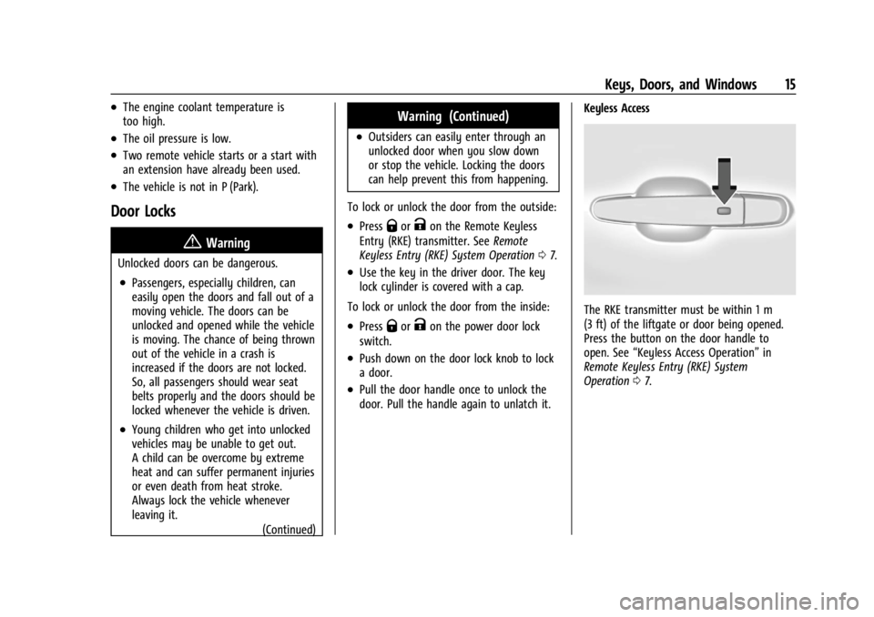
door. Pull the handle again to unlatch it. Keyless Access
The RKE transmitter must be within 1 m
(3 ft) of the liftgate or door being opened.
Press the button on the door handle to
open. See
“Keyless Access Operation” in
Remote Keyless Entry (RKE) System
Operation 07.
Page 21 of 396
GMC Acadia/Acadia Denali Owner Manual (GMNA-Localizing-U.S./Canada/
Mexico-14608671) - 2021 - CRC - 10/26/20
20 Keys, Doors, and Windows
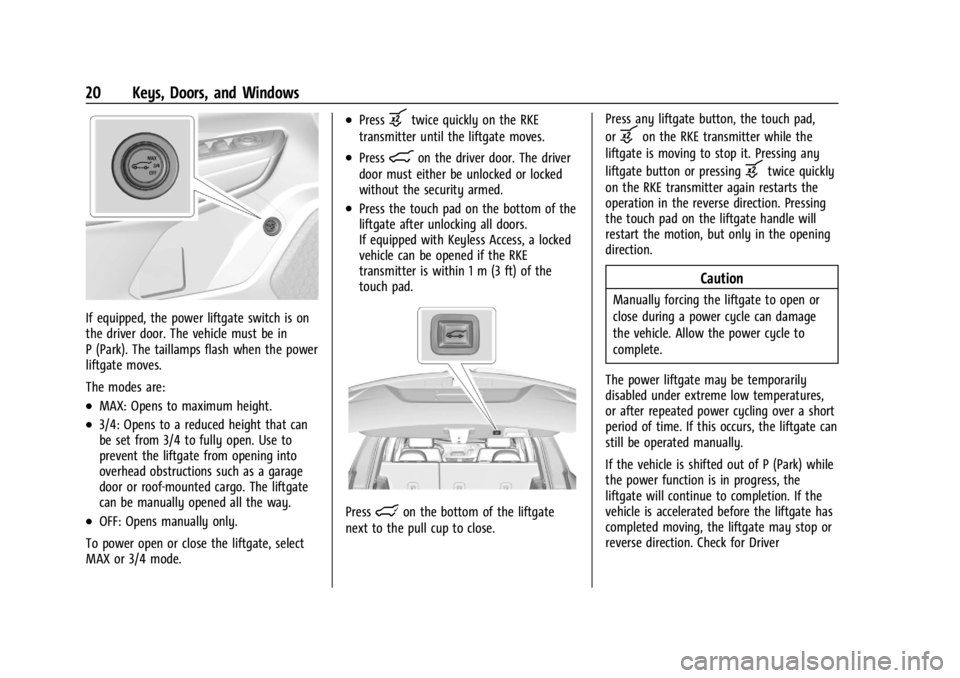
If equipped, the power liftgate switch is on
the driver door. The vehicle must be in
P (Park). The taillamps flash when the power
liftgate moves.
The modes are:
.MAX: Opens to maximum height.
.3/4: Opens to a reduced height that can
be set from 3/4 to fully open. Use to
prevent the liftgate from opening into
overhead obstructions such as a garage
door or roof-mounted cargo. The liftgate
can be manually opened all the way.
.OFF: Opens manually only.
To power open or close the liftgate, select
MAX or 3/4 mode.
.Pressbtwice quickly on the RKE
transmitter until the liftgate moves.
.Press8on the driver door. The driver
door must either be unlocked or locked
without the security armed.
.Press the touch pad on the bottom of the
liftgate after unlocking all doors.
If equipped with Keyless Access, a locked
vehicle can be opened if the RKE
transmitter is within 1 m (3 ft) of the
touch pad.
Presslon the bottom of the liftgate
next to the pull cup to close. Press any liftgate button, the touch pad,
or
bon the RKE transmitter while the
liftgate is moving to stop it. Pressing any
liftgate button or pressing
btwice quickly
on the RKE transmitter again restarts the
operation in the reverse direction. Pressing
the touch pad on the liftgate handle will
restart the motion, but only in the opening
direction.
Caution
Manually forcing the liftgate to open or
close during a power cycle can damage
the vehicle. Allow the power cycle to
complete.
The power liftgate may be temporarily
disabled under extreme low temperatures,
or after repeated power cycling over a short
period of time. If this occurs, the liftgate can
still be operated manually.
If the vehicle is shifted out of P (Park) while
the power function is in progress, the
liftgate will continue to completion. If the
vehicle is accelerated before the liftgate has
completed moving, the liftgate may stop or
reverse direction. Check for Driver
Page 42 of 396
GMC Acadia/Acadia Denali Owner Manual (GMNA-Localizing-U.S./Canada/
Mexico-14608671) - 2021 - CRC - 10/26/20
Seats and Restraints 41
Seat Entry Memory
The vehicle identifies the number of the
current driver’s RKE transmitter (1–8). See
Remote Keyless Entry (RKE) System
Operation07. If the RKE transmitter is 1 or
2, and Seat Entry Memory is enabled in
vehicle personalization, the positions saved
to the same memory button number 1 or 2
are automatically recalled when the vehicle
is turned on, or turned from off to ACC/
ACCESSORY. RKE transmitters 3–8 will not
provide automatic memory recalls.
To turn Seat Entry Memory on or off, see
“Vehicle Personalization Settings” previously
in this section and Vehicle Personalization
0 123.
The transmission must be in P (Park) to start
Seat Entry Memory. Seat Entry Memory
recall will complete if the vehicle is shifted
out of P (Park) prior to reaching the saved
memory position.
To stop Seat Entry Memory recall
movement, turn the vehicle off or press any
of the following controls:
.Power seat
.Memory SET, 1, 2, orB
.Power mirror, with the driver or
passenger side mirror selected
.Power steering wheel, if equipped
If the saved memory seat position does not
automatically recall or recalls to the wrong
positions, the driver’s RKE transmitter
number (1 or 2) may not match the memory
button number that positions were saved to.
Try storing the position to the other
memory button or try the other RKE
transmitter.
Seat Exit Memory
Seat Exit Memory is not linked to an RKE
transmitter. The position saved to
Bis
used for all drivers. To turn Seat Exit
Memory on or off, see "Vehicle
Personalization Settings" previously in this
section and Vehicle Personalization 0123.
If turned on, the position saved to
Bis
automatically recalled when one of the
following occurs:
.The vehicle is turned off and the driver
door is opened within a short time.
.The vehicle is turned off with the driver
door open.
To stop Seat Exit Memory movement, press
any of the following memory controls:
.Power seat
.Memory SET, 1, 2, orB
.Power mirror, with the driver or
passenger side mirror selected
.Power steering wheel, if equipped
Obstructions
If something has blocked the driver seat
and/or power steering wheel while recalling
a memory position, the recall may stop.
Remove the obstruction and try the recall
again. If the memory position still does not
recall, see your dealer.
Heated and Ventilated Front
Seats
{Warning
If temperature change or pain to the skin
cannot be felt, the seat heater may cause
burns. To reduce the risk of burns, use
care when using the seat heater,
especially for long periods of time. Do
not place anything on the seat that
insulates against heat, such as a blanket,
cushion, cover, or similar item. This may
cause the seat heater to overheat. An
overheated seat heater may cause a burn
or may damage the seat.
Page 43 of 396
GMC Acadia/Acadia Denali Owner Manual (GMNA-Localizing-U.S./Canada/
Mexico-14608671) - 2021 - CRC - 10/26/20
42 Seats and Restraints
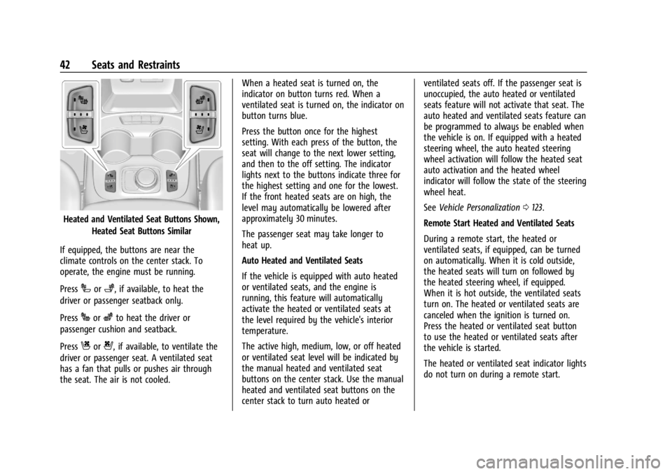
Heated and Ventilated Seat Buttons Shown,Heated Seat Buttons Similar
If equipped, the buttons are near the
climate controls on the center stack. To
operate, the engine must be running.
Press
Ior+, if available, to heat the
driver or passenger seatback only.
Press
Jorzto heat the driver or
passenger cushion and seatback.
Press
Cor{, if available, to ventilate the
driver or passenger seat. A ventilated seat
has a fan that pulls or pushes air through
the seat. The air is not cooled. When a heated seat is turned on, the
indicator on button turns red. When a
ventilated seat is turned on, the indicator on
button turns blue.
Press the button once for the highest
setting. With each press of the button, the
seat will change to the next lower setting,
and then to the off setting. The indicator
lights next to the buttons indicate three for
the highest setting and one for the lowest.
If the front heated seats are on high, the
level may automatically be lowered after
approximately 30 minutes.
The passenger seat may take longer to
heat up.
Auto Heated and Ventilated Seats
If the vehicle is equipped with auto heated
or ventilated seats, and the engine is
running, this feature will automatically
activate the heated or ventilated seats at
the level required by the vehicle's interior
temperature.
The active high, medium, low, or off heated
or ventilated seat level will be indicated by
the manual heated and ventilated seat
buttons on the center stack. Use the manual
heated and ventilated seat buttons on the
center stack to turn auto heated orventilated seats off. If the passenger seat is
unoccupied, the auto heated or ventilated
seats feature will not activate that seat. The
auto heated and ventilated seats feature can
be programmed to always be enabled when
the vehicle is on. If equipped with a heated
steering wheel, the auto heated steering
wheel activation will follow the heated seat
auto activation and the heated wheel
indicator will follow the state of the steering
wheel heat.
See
Vehicle Personalization 0123.
Remote Start Heated and Ventilated Seats
During a remote start, the heated or
ventilated seats, if equipped, can be turned
on automatically. When it is cold outside,
the heated seats will turn on followed by
the heated steering wheel, if equipped.
When it is hot outside, the ventilated seats
turn on. The heated or ventilated seats are
canceled when the ignition is turned on.
Press the heated or ventilated seat button
to use the heated or ventilated seats after
the vehicle is started.
The heated or ventilated seat indicator lights
do not turn on during a remote start.
Page 44 of 396
GMC Acadia/Acadia Denali Owner Manual (GMNA-Localizing-U.S./Canada/
Mexico-14608671) - 2021 - CRC - 10/26/20
Seats and Restraints 43
The temperature performance of an
unoccupied seat may be reduced. This is
normal.
The remote start heated or ventilated seats
may be enabled or disabled in the vehicle
personalization menu. SeeRemote Vehicle
Start 013 and
Vehicle Personalization 0123.
Rear Seats
Rear Seat Reminder
If equipped, the message REAR SEAT
REMINDER LOOK IN REAR SEAT displays
under certain conditions indicating there
may be an item or passenger in the rear
seat. Check before exiting the vehicle.
This feature will activate when a second row
door is opened while the vehicle is on or up
to 10 minutes before the vehicle is turned
on. There will be an alert when the vehicle
is turned off. The alert does not directly
detect objects in the rear seat; instead,
under certain conditions, it detects when a
rear door is opened and closed, indicating
that there may be something in the
rear seat. The feature is active only once each time
the vehicle is turned on and off, and will
require reactivation by opening and closing
the second row doors. There may be an
alert even when there is nothing in the rear
seat; for example, if a child entered the
vehicle through the rear door and left the
vehicle without the vehicle being shut off.
The feature can be turned on or off. See
Vehicle Personalization
0123.
Rear Seat Adjustment
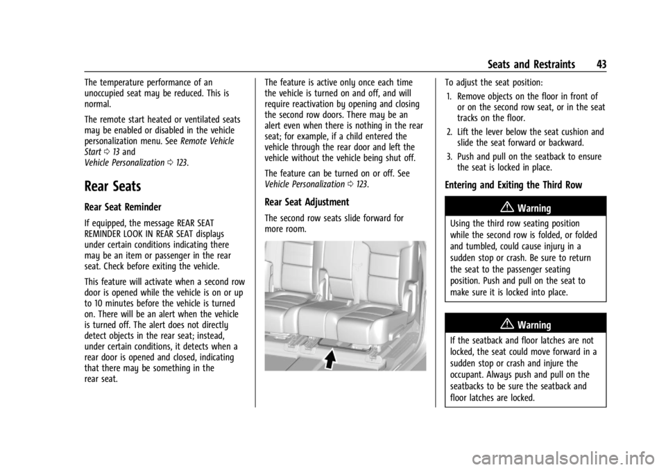
The second row seats slide forward for
more room.
To adjust the seat position:
1. Remove objects on the floor in front of or on the second row seat, or in the seat
tracks on the floor.
2. Lift the lever below the seat cushion and slide the seat forward or backward.
3. Push and pull on the seatback to ensure the seat is locked in place.
Entering and Exiting the Third Row
{Warning
Using the third row seating position
while the second row is folded, or folded
and tumbled, could cause injury in a
sudden stop or crash. Be sure to return
the seat to the passenger seating
position. Push and pull on the seat to
make sure it is locked into place.
{Warning
If the seatback and floor latches are not
locked, the seat could move forward in a
sudden stop or crash and injure the
occupant. Always push and pull on the
seatbacks to be sure the seatback and
floor latches are locked.
Page 46 of 396
GMC Acadia/Acadia Denali Owner Manual (GMNA-Localizing-U.S./Canada/
Mexico-14608671) - 2021 - CRC - 10/26/20
Seats and Restraints 45
Reclining the Seatbacks
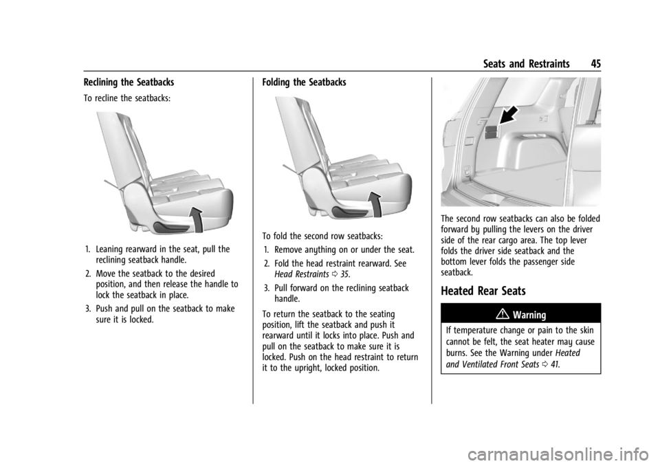
To recline the seatbacks:
1. Leaning rearward in the seat, pull thereclining seatback handle.
2. Move the seatback to the desired position, and then release the handle to
lock the seatback in place.
3. Push and pull on the seatback to make sure it is locked.
Folding the Seatbacks
To fold the second row seatbacks:
1. Remove anything on or under the seat.
2. Fold the head restraint rearward. See Head Restraints 035.
3. Pull forward on the reclining seatback handle.
To return the seatback to the seating
position, lift the seatback and push it
rearward until it locks into place. Push and
pull on the seatback to make sure it is
locked. Push on the head restraint to return
it to the upright, locked position.
The second row seatbacks can also be folded
forward by pulling the levers on the driver
side of the rear cargo area. The top lever
folds the driver side seatback and the
bottom lever folds the passenger side
seatback.
Heated Rear Seats
{Warning
If temperature change or pain to the skin
cannot be felt, the seat heater may cause
burns. See the Warning under Heated
and Ventilated Front Seats 041.
Page 90 of 396
GMC Acadia/Acadia Denali Owner Manual (GMNA-Localizing-U.S./Canada/
Mexico-14608671) - 2021 - CRC - 10/26/20
Instruments and Controls 89
Instruments and Controls
Controls
Steering Wheel Adjustment . . . . . . . . . . . . 90
Steering Wheel Controls . . . . . . . . . . . . . . . 90
Heated Steering Wheel . . . . . . . . . . . . . . . . 90
Horn . . . . . . . . . . . . . . . . . . . . . . . . . . . . . . . . . . . . 91
Windshield Wiper/Washer . . . . . . . . . . . . . . 91
Rear Window Wiper/Washer . . . . . . . . . . . 92
Compass . . . . . . . . . . . . . . . . . . . . . . . . . . . . . . . 92
Clock . . . . . . . . . . . . . . . . . . . . . . . . . . . . . . . . . . . 93
Power Outlets . . . . . . . . . . . . . . . . . . . . . . . . . . 93
Wireless Charging . . . . . . . . . . . . . . . . . . . . . . 94
Warning Lights, Gauges, and Indicators
Warning Lights, Gauges, andIndicators . . . . . . . . . . . . . . . . . . . . . . . . . . . . 96
Instrument Cluster (Base and Midlevel) . . . . . . . . . . . . . . . . . . . . . . . . . . . . . 97
Instrument Cluster (Uplevel) . . . . . . . . . . . 100
Speedometer . . . . . . . . . . . . . . . . . . . . . . . . . . 102
Odometer . . . . . . . . . . . . . . . . . . . . . . . . . . . . . 102
Trip Odometer . . . . . . . . . . . . . . . . . . . . . . . . . 102
Tachometer . . . . . . . . . . . . . . . . . . . . . . . . . . . . 102
Fuel Gauge . . . . . . . . . . . . . . . . . . . . . . . . . . . . 102
Engine Oil Temperature Gauge . . . . . . . . 103
Engine Coolant Temperature Gauge . . . 104
Voltmeter Gauge . . . . . . . . . . . . . . . . . . . . . . 104
Seat Belt Reminders . . . . . . . . . . . . . . . . . . . 105
Airbag Readiness Light . . . . . . . . . . . . . . . . 105 Passenger Airbag Status Indicator . . . . . 106
Charging System Light . . . . . . . . . . . . . . . . . 107
Malfunction Indicator Lamp (Check
Engine Light) . . . . . . . . . . . . . . . . . . . . . . . . 107
Brake System Warning Light . . . . . . . . . . 108
Electric Parking Brake Light . . . . . . . . . . . . 109
Service Electric Parking Brake Light
(Uplevel and Midlevel
Cluster Only) . . . . . . . . . . . . . . . . . . . . . . . . 109
Antilock Brake System (ABS) Warning Light . . . . . . . . . . . . . . . . . . . . . . . . . . . . . . . . . 110
Gear Shifting Light . . . . . . . . . . . . . . . . . . . . . 110
Tow/Haul Mode Light . . . . . . . . . . . . . . . . . 110
Hill Descent Control Light . . . . . . . . . . . . . . 110
Lane Keep Assist (LKA) Light . . . . . . . . . . . 110
Vehicle Ahead Indicator . . . . . . . . . . . . . . . . 111
Pedestrian Ahead Indicator . . . . . . . . . . . . . 111
Traction Off Light . . . . . . . . . . . . . . . . . . . . . . 111
StabiliTrak OFF Light . . . . . . . . . . . . . . . . . . . 112
Traction Control System (TCS)/ StabiliTrak Light . . . . . . . . . . . . . . . . . . . . . . 112
Engine Coolant Temperature Warning Light . . . . . . . . . . . . . . . . . . . . . . . . . . . . . . . . . 112
Tire Pressure Light . . . . . . . . . . . . . . . . . . . . . 113
Engine Oil Pressure Light . . . . . . . . . . . . . . . 113
Low Fuel Warning Light . . . . . . . . . . . . . . . . 114
Security Light . . . . . . . . . . . . . . . . . . . . . . . . . . 114
High-Beam On Light . . . . . . . . . . . . . . . . . . . 114
Front Fog Lamp Light . . . . . . . . . . . . . . . . . . 114
Lamps On Reminder . . . . . . . . . . . . . . . . . . . 114 Cruise Control Light . . . . . . . . . . . . . . . . . . . . 115
Door Ajar Light . . . . . . . . . . . . . . . . . . . . . . . . . 115
Information Displays
Driver Information Center
(DIC) (Base) . . . . . . . . . . . . . . . . . . . . . . . . . . 115
Driver Information Center (DIC) (Midlevel and Uplevel) . . . . . . . . . . . . . . . 117
Head-Up Display (HUD) . . . . . . . . . . . . . . . . 119
Vehicle Messages
Vehicle Messages . . . . . . . . . . . . . . . . . . . . . . 122
Engine Power Messages . . . . . . . . . . . . . . . 123
Vehicle Speed Messages . . . . . . . . . . . . . . . 123
Vehicle Personalization
Vehicle Personalization . . . . . . . . . . . . . . . . . 123
Universal Remote System
Universal Remote System . . . . . . . . . . . . . . 127
Universal Remote System Programming . . . . . . . . . . . . . . . . . . . . . . . . 127
Universal Remote System Operation . . . 129