engine GMC CANYON 2023 Owners Manual
[x] Cancel search | Manufacturer: GMC, Model Year: 2023, Model line: CANYON, Model: GMC CANYON 2023Pages: 371, PDF Size: 7.41 MB
Page 284 of 371
GMC Canyon/Canyon Denali Owner Manual (GMNA-Localizing-U.S./Canada/
Mexico-16510661) - 2023 - CRC - 11/29/22
Vehicle Care 283
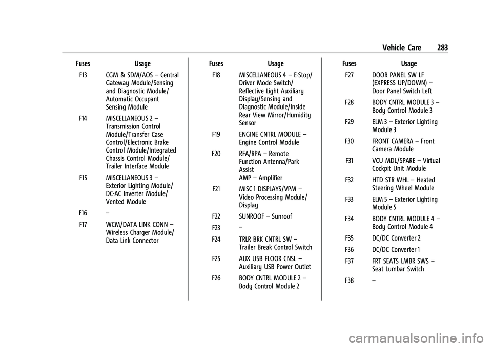
FusesUsage
F13 CGM & SDM/AOS –Central
Gateway Module/Sensing
and Diagnostic Module/
Automatic Occupant
Sensing Module
F14 MISCELLANEOUS 2 –
Transmission Control
Module/Transfer Case
Control/Electronic Brake
Control Module/Integrated
Chassis Control Module/
Trailer Interface Module
F15 MISCELLANEOUS 3 –
Exterior Lighting Module/
DC-AC Inverter Module/
Vented Module
F16 –
F17 WCM/DATA LINK CONN –
Wireless Charger Module/
Data Link Connector Fuses
Usage
F18 MISCELLANEOUS 4 –E-Stop/
Driver Mode Switch/
Reflective Light Auxiliary
Display/Sensing and
Diagnostic Module/Inside
Rear View Mirror/Humidity
Sensor
F19 ENGINE CNTRL MODULE –
Engine Control Module
F20 RFA/RPA –Remote
Function Antenna/Park
Assist
AMP –Amplifier
F21 MISC 1 DISPLAYS/VPM –
Video Processing Module/
Display
F22 SUNROOF –Sunroof
F23 –
F24 TRLR BRK CNTRL SW –
Trailer Break Control Switch
F25 AUX USB FLOOR CNSL –
Auxiliary USB Power Outlet
F26 BODY CNTRL MODULE 2 –
Body Control Module 2 Fuses
Usage
F27 DOOR PANEL SW LF (EXPRESS UP/DOWN) –
Door Panel Switch Left
F28 BODY CNTRL MODULE 3 –
Body Control Module 3
F29 ELM 3 –Exterior Lighting
Module 3
F30 FRONT CAMERA –Front
Camera Module
F31 VCU MDL/SPARE –Virtual
Cockpit Unit Module
F32 HTD STR WHL –Heated
Steering Wheel Module
F33 ELM 5 –Exterior Lighting
Module 5
F34 BODY CNTRL MODULE 4 –
Body Control Module 4
F35 DC/DC Converter 2
F36 DC/DC Converter 1 F37 FRT SEATS LMBR SWS –
Seat Lumbar Switch
F38 –
Page 288 of 371
GMC Canyon/Canyon Denali Owner Manual (GMNA-Localizing-U.S./Canada/
Mexico-16510661) - 2023 - CRC - 11/29/22
Vehicle Care 287
week of the year 2020 would have a
4-digit DOT date of 0320. Week 01 is
the first full week (Sunday through
Saturday) of each year.
(5) Tire Identification Number (TIN)
:
The letters and numbers following the
DOT code are the Tire Identification
Number (TIN). The TIN shows the
manufacturer and plant code, tire size,
and date the tire was manufactured.
The TIN is molded onto both sides of
the tire, although only one side may
have the date of manufacture.
(6) Tire Ply Material
:The type of cord
and number of plies in the sidewall and
under the tread.
(7) Single Tire Maximum Load
:
Maximum load that can be carried and
the maximum pressure needed to
support that load when used as a
single. For information on
recommended tire pressure see Tire
Pressure 0290 and
Vehicle Load Limits 0162.
Tire Designations
Tire Size
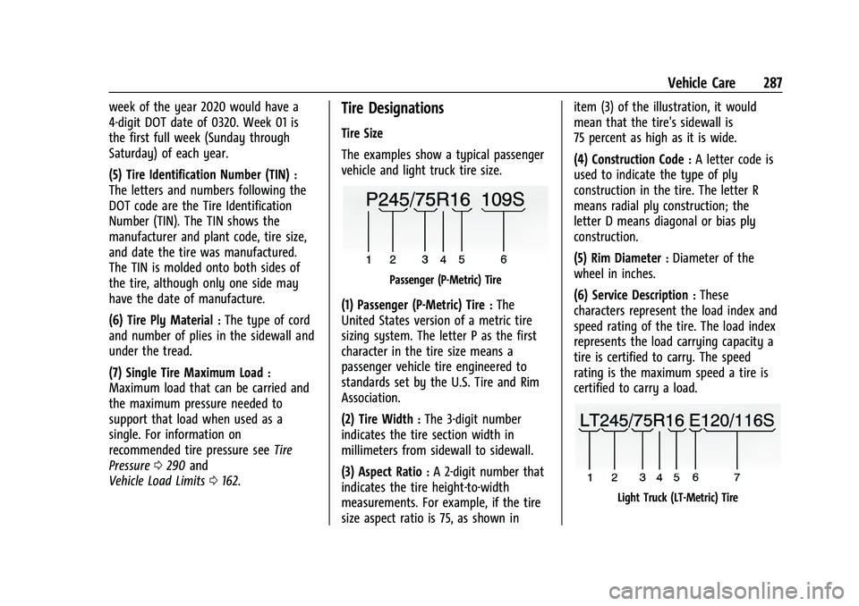
The examples show a typical passenger
vehicle and light truck tire size.
Passenger (P-Metric) Tire
(1) Passenger (P-Metric) Tire:The
United States version of a metric tire
sizing system. The letter P as the first
character in the tire size means a
passenger vehicle tire engineered to
standards set by the U.S. Tire and Rim
Association.
(2) Tire Width
:The 3-digit number
indicates the tire section width in
millimeters from sidewall to sidewall.
(3) Aspect Ratio
:A 2-digit number that
indicates the tire height-to-width
measurements. For example, if the tire
size aspect ratio is 75, as shown in item (3) of the illustration, it would
mean that the tire's sidewall is
75 percent as high as it is wide.
(4) Construction Code
:A letter code is
used to indicate the type of ply
construction in the tire. The letter R
means radial ply construction; the
letter D means diagonal or bias ply
construction.
(5) Rim Diameter
:Diameter of the
wheel in inches.
(6) Service Description
:These
characters represent the load index and
speed rating of the tire. The load index
represents the load carrying capacity a
tire is certified to carry. The speed
rating is the maximum speed a tire is
certified to carry a load.
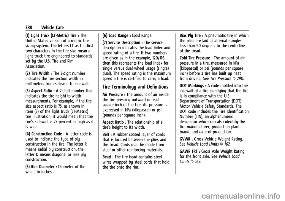
Light Truck (LT-Metric) Tire
Page 289 of 371
GMC Canyon/Canyon Denali Owner Manual (GMNA-Localizing-U.S./Canada/
Mexico-16510661) - 2023 - CRC - 11/29/22
288 Vehicle Care
(1) Light Truck (LT-Metric) Tire:The
United States version of a metric tire
sizing system. The letters LT as the first
two characters in the tire size mean a
light truck tire engineered to standards
set by the U.S. Tire and Rim
Association.
(2) Tire Width
:The 3-digit number
indicates the tire section width in
millimeters from sidewall to sidewall.
(3) Aspect Ratio
:A 2-digit number that
indicates the tire height-to-width
measurements. For example, if the tire
size aspect ratio is 75, as shown in
item (3) of the light truck (LT-Metric)
tire illustration, it would mean that the
tire's sidewall is 75 percent as high as it
is wide.
(4) Construction Code
:A letter code is
used to indicate the type of ply
construction in the tire. The letter R
means radial ply construction; the
letter D means diagonal or bias ply
construction.
(5) Rim Diameter
:Diameter of the
wheel in inches. (6) Load Range
:Load Range.
(7) Service Description
:The service
description indicates the load index and
speed rating of a tire. If two numbers
are given as in the example, 120/116,
then this represents the load index for
single versus dual wheel usage (single/
dual). The speed rating is the maximum
speed a tire is certified to carry a load.
Tire Terminology and Definitions
Air Pressure:The amount of air inside
the tire pressing outward on each
square inch of the tire. Air pressure is
expressed in kPa (kilopascal) or psi
(pounds per square inch).
Aspect Ratio
:The relationship of a
tire's height to its width.
Belt
:A rubber coated layer of cords
that is located between the plies and
the tread. Cords may be made from
steel or other reinforcing materials.
Bead
:The tire bead contains steel
wires wrapped by steel cords that hold
the tire onto the rim. Bias Ply Tire
:A pneumatic tire in which
the plies are laid at alternate angles
less than 90 degrees to the centerline
of the tread.
Cold Tire Pressure
:The amount of air
pressure in a tire, measured in kPa
(kilopascal) or psi (pounds per square
inch) before a tire has built up heat
from driving. See Tire Pressure0290.
DOT Markings
:A code molded into the
sidewall of a tire signifying that the tire
is in compliance with the U.S.
Department of Transportation (DOT)
Motor Vehicle Safety Standards. The
DOT code includes the Tire Identification
Number (TIN), an alphanumeric
designator which can also identify the
tire manufacturer, production plant,
brand, and date of production.
GVWR
:Gross Vehicle Weight Rating.
See Vehicle Load Limits 0162.
GAWR FRT
:Gross Axle Weight Rating
for the front axle. See Vehicle Load
Limits 0162.
Page 291 of 371
GMC Canyon/Canyon Denali Owner Manual (GMNA-Localizing-U.S./Canada/
Mexico-16510661) - 2023 - CRC - 11/29/22
290 Vehicle Care
molded into the sidewall of the tire.
SeeUniform Tire Quality Grading
0 300.
Vehicle Capacity Weight
:The number
of designated seating positions
multiplied by 68 kg (150 lbs) plus the
rated cargo load. See Vehicle Load
Limits 0162.
Vehicle Maximum Load on the Tire
:
Load on an individual tire due to curb
weight, accessory weight, occupant
weight, and cargo weight.
Vehicle Placard
:A label permanently
attached to a vehicle showing the
vehicle's capacity weight and the
original equipment tire size and
recommended inflation pressure. See
“Tire and Loading Information Label”
under Vehicle Load Limits 0162.
Tire Pressure
Tires need the correct amount of air
pressure to operate effectively.
{Warning
Neither tire underinflation nor
overinflation is good. Underinflated
tires, or tires that do not have
enough air, can result in:
.Tire overloading and overheating,
which could lead to a blowout
.Premature or irregular wear
.Poor handling
.Reduced fuel economy for
internal combustion engine
vehicles
.Reduced range for electric vehicles
Overinflated tires, or tires that have
too much air, can result in:
.Unusual wear
.Poor handling
.Rough ride
.Needless damage from road
hazards The Tire and Loading Information label
on the vehicle indicates the original
equipment tires and the correct cold
tire inflation pressures. The
recommended pressure is the minimum
air pressure needed to support the
vehicle's maximum load carrying
capacity.
For additional information regarding
how much weight the vehicle can carry,
and an example of the Tire and Loading
Information label, see
Vehicle Load
Limits 0162. How the vehicle is loaded
affects vehicle handling and ride
comfort. Never load the vehicle with
more weight than it was designed to
carry.
When to Check
Check the pressure of the tires once a
month or more.
Do not forget the spare, if the vehicle
has one. See Full-Size Spare Tire 0311
for additional information.
Page 295 of 371
GMC Canyon/Canyon Denali Owner Manual (GMNA-Localizing-U.S./Canada/
Mexico-16510661) - 2023 - CRC - 11/29/22
294 Vehicle Care
{Warning
Overinflating a tire could cause the tire
to rupture and you or others could be
injured. Do not exceed the maximum
pressure listed on the tire sidewall. See
Tire Sidewall Labeling0285 and
Vehicle Load Limits 0162.
If the tire is overinflated by more than
35 kPa (5 psi), the horn will sound multiple
times and the turn signal lamp will continue
to flash for several seconds after filling
stops. To release and correct the pressure,
while the turn signal lamp is still flashing,
briefly press the center of the valve stem.
When the recommended pressure is reached,
the horn sounds once.
If the turn signal lamp does not flash within
15 seconds after starting to inflate the tire,
the tire fill alert has not been activated or is
not working.
If the hazard warning flashers are on, the
tire fill alert visual feedback will not work
properly. The TPMS will not activate the tire fill alert
properly under the following conditions:.There is interference from an external
device or transmitter.
.The air pressure from the inflation device
is not sufficient to inflate the tire.
.There is a malfunction in the TPMS.
.There is a malfunction in the horn or turn
signal lamps.
.The TPMS sensor identification code is not
registered to the system.
.The TPMS sensor battery is low.
If the tire fill alert does not operate due to
TPMS interference, move the vehicle about
1 m (3 ft) back or forward and try again.
If the tire fill alert feature is not working,
use a tire pressure gauge.
Air Down Mode (If Equipped)
Air Down Mode allows the driver to set a
custom tire pressure for better traction
during off-road driving. Visual and audible
alerts outside of the vehicle will alert the
driver when the desired tire pressure has
been reached. To enable Air Down Mode:
1. Park the vehicle in a safe, level place.
2. Place the vehicle in P (Park).
3. Place the vehicle in ON/RUN or press and hold the ENGINE START/STOP button for
more than five seconds. See Ignition
Positions 0167.
4. Touch the Off-Road app icon on the infotainment home screen.
5. Touch the Air Down Mode icon.
6. Select the target pressure, then press START.
7. Choose which tire to deflate. Remove the valve cap, then press and hold the tire
valve stem.
During tire deflation, the turn signal
lamp closest to the tire being deflated
will start flashing.
When the target pressure you selected
in Step 6 is reached, the horn sounds
once and the turn signal lamp will stop
flashing and turn solid for several
seconds before turning off. Replace the
valve cap. Wait for the turn signal lamp
to turn off before deflating the next tire.
If you deflate the next tire while the
turn signal lamp is still on, the Air Down
Mode will not work properly.
Page 296 of 371
GMC Canyon/Canyon Denali Owner Manual (GMNA-Localizing-U.S./Canada/
Mexico-16510661) - 2023 - CRC - 11/29/22
Vehicle Care 295
Repeat Step 7 until all tires have been
deflated. Same steps can be followed for
inflating all tires to target pressure.
While in Air Down Mode, after all tires have
been deflated lower than the vehicle’s
recommended tire pressure, the low tire
pressure warning light and the DIC warning
message may come on for all tires.
Due to late air adjustment in a tire, the tire
pressure may change by 4 to 8 kpa (0.6 to
1.2 psi) after a few minutes, once you have
stopped deflation.
Ensure that the target pressure you select is
above or below your vehicle’s current tire
pressures by a least 20 kpa (3 psi).
If the tire is underinflated or overinflated by
more than 35 kPa (5 psi) from the target
pressure you selected in Step 6, the horn
will sound multiple times and the turn
signal lamp will continue to flash for several
seconds after tire pressure adjustment stops.
To correct the pressure, while the turn
signal lamp is still flashing, add air to inflate
the tire or briefly press the center of the
valve stem to deflate the tire. When the
target pressure you selected in Step 6 is
reached, the horn sounds once and the turn
signal lamp will stop flashing and turn solid
for several seconds before turning off. If the turn signal lamp does not flash within
15 seconds after starting to inflate the tire,
the Air Down Mode has not been activated
or is not working.
If the hazard warning flashers are on, the
Air Down Mode visual feedback will not
work properly.
The Air Down Mode will not work properly
under the following conditions:
.There is interference from an external
device or transmitter.
.The air pressure from the inflation device
is not sufficient to inflate the tire.
.There is a malfunction in the TPMS.
.There is a malfunction in the horn or turn
signal lamps.
.The TPMS sensor identification code is not
registered to the system.
.The TPMS sensor battery is low.
.The vehicle is not in P (Park).
.The vehicle is off.
.START was not pressed after selecting the
target tire pressure in the Air Down
Mode app.
If the Air Down Mode does not operate due
to TPMS interference, move the vehicle
about 1 m (3 ft) back or forward and try again. If the Air Down Mode is not working,
use a tire pressure gauge to confirm tire
pressure.
{Warning
Neither tire underinflation nor
overinflation is good. Underinflated
tires, or tires that do not have
enough air, can result in:
.Tire overloading and overheating,
which could lead to a blowout
.Premature or irregular wear
.Poor handling
.Reduced fuel economy for
internal combustion engine
vehicles
.Reduced range for electric vehicles
Overinflated tires, or tires that have
too much air, can result in:
.Unusual wear
.Poor handling
.Rough ride
.Needless damage from road
hazards
Page 304 of 371
GMC Canyon/Canyon Denali Owner Manual (GMNA-Localizing-U.S./Canada/
Mexico-16510661) - 2023 - CRC - 11/29/22
Vehicle Care 303
If your vehicle is loaded at or near
maximum cargo capacity, it may be difficult
to fit the jack under the vehicle due to the
environment (shoulder slope, road debris,
etc.). Removal of some weight may improve
the ability to fit the jack under the vehicle
at the correct jacking location.
{Warning
Changing a tire can be dangerous. The
vehicle can slip off the jack and roll over
or fall causing injury or death. Find a
level place to change the tire. To help
prevent the vehicle from moving:1. Set the parking brake firmly.
2. Shift the vehicle to P (Park).
3. For vehicles with four-wheel drive with an N (Neutral) transfer case
position, be sure the transfer case is
in a drive gear —not in N (Neutral).
4. Turn off the engine and do not restart while the vehicle is raised.
5. Do not allow passengers to remain in the vehicle.
(Continued)
Warning (Continued)
6. Place wheel blocks, if equipped, onboth sides of the tire at the opposite
corner of the tire being changed.
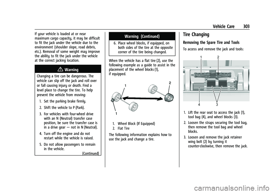
When the vehicle has a flat tire (2), use the
following example as a guide to assist in the
placement of the wheel blocks (1),
if equipped.
1. Wheel Block (If Equipped)
2. Flat Tire
The following information explains how to
use the jack and change a tire.
Tire Changing
Removing the Spare Tire and Tools
To access and remove the jack and tools:
1. Lift the rear seat to access the jack (1), tool bag (4), and wheel blocks (3).
2. Loosen the straps securing the tool bag, then remove the tool bag and wheel
blocks.
3. Loosen and remove the jack retainer wing bolt (2) by turning it
counter-clockwise, then remove the jack.
Page 314 of 371
GMC Canyon/Canyon Denali Owner Manual (GMNA-Localizing-U.S./Canada/
Mexico-16510661) - 2023 - CRC - 11/29/22
Vehicle Care 313
Warning (Continued)
If you do not follow these steps exactly,
some or all of these things can hurt you.
Caution
Ignoring these steps could result in costly
damage to the vehicle that would not be
covered by the vehicle warranty. Trying
to start the vehicle by pushing or pulling
it will not work, and it could damage the
vehicle.
Caution
If the jumper cables are connected or
removed in the wrong order, electrical
shorting may occur and damage the
vehicle. The repairs would not be covered
by the vehicle warranty. Always connect
and remove the jumper cables in the
correct order, making sure that the cables
do not touch each other or other metal.
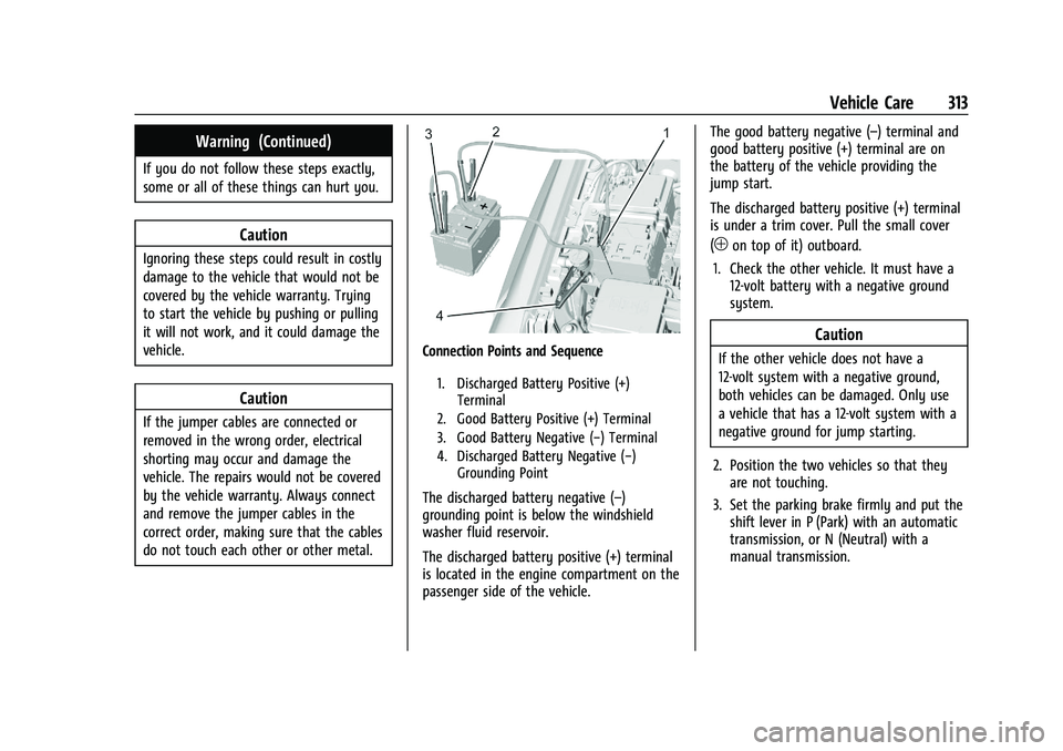
Connection Points and Sequence
1. Discharged Battery Positive (+)Terminal
2. Good Battery Positive (+) Terminal
3. Good Battery Negative (−) Terminal
4. Discharged Battery Negative (−) Grounding Point
The discharged battery negative (–)
grounding point is below the windshield
washer fluid reservoir.
The discharged battery positive (+) terminal
is located in the engine compartment on the
passenger side of the vehicle. The good battery negative (–) terminal and
good battery positive (+) terminal are on
the battery of the vehicle providing the
jump start.
The discharged battery positive (+) terminal
is under a trim cover. Pull the small cover
(
1on top of it) outboard.
1. Check the other vehicle. It must have a 12-volt battery with a negative ground
system.
Caution
If the other vehicle does not have a
12-volt system with a negative ground,
both vehicles can be damaged. Only use
a vehicle that has a 12-volt system with a
negative ground for jump starting.
2. Position the two vehicles so that they are not touching.
3. Set the parking brake firmly and put the shift lever in P (Park) with an automatic
transmission, or N (Neutral) with a
manual transmission.
Page 315 of 371
GMC Canyon/Canyon Denali Owner Manual (GMNA-Localizing-U.S./Canada/
Mexico-16510661) - 2023 - CRC - 11/29/22
314 Vehicle Care
Caution
If any accessories are left on or plugged
in during the jump starting procedure,
they could be damaged. The repairs
would not be covered by the vehicle
warranty. Whenever possible, turn off or
unplug all accessories on either vehicle
when jump starting.
4. Turn the ignition off. Turn off all lights and accessories in both vehicles, except
the hazard warning flashers if needed.
{Warning
An electric fan can start up even when
the engine is not running and can injure
you. Keep hands, clothing, and tools
away from any underhood electric fan.
{Warning
Using a match near a battery can cause
battery gas to explode. People have been
hurt doing this, and some have been
blinded. Use a flashlight if you need
more light.
(Continued)
Warning (Continued)
Battery fluid contains acid that can burn
you. Do not get it on you. If you
accidentally get it in your eyes or on
your skin, flush the place with water and
get medical help immediately.
{Warning
Fans or other moving engine parts can
injure you badly. Keep your hands away
from moving parts once the engine is
running.
5. Connect one end of the red positive (+) cable to the discharged battery
positive (+) terminal.
6. Connect the other end of the red positive (+) cable to the good battery
positive (+) terminal.
7. Connect one end of the black negative (–) cable to the good battery negative
(–) terminal.
8. Connect the other end of the black negative (–) cable to the discharged
battery negative (–) grounding point. 9. Start the engine in the vehicle with the
good battery and run the engine at idle
speed for at least four minutes.
10. Try to start the vehicle that had the dead battery. If it will not start after a
few tries, it probably needs service.
Jumper Cable Removal
Reverse the sequence exactly when
removing the jumper cables.
After starting the disabled vehicle and
removing the jumper cables, allow it to idle
for several minutes.
Close the small cover (
1on top of it).
Ensure the locking feature (located inboard)
latches completely with the rest of the
cover.
Towing the Vehicle
Transporting a Disabled Vehicle
Caution
Incorrectly transporting a disabled vehicle
may cause damage to the vehicle. Use
proper tire straps to secure the vehicle to
the flatbed tow truck. Do not strap or
(Continued)
Page 318 of 371
GMC Canyon/Canyon Denali Owner Manual (GMNA-Localizing-U.S./Canada/
Mexico-16510661) - 2023 - CRC - 11/29/22
Vehicle Care 317
Dinghy Towing (Vehicles with a
Two-Speed Transfer Case)
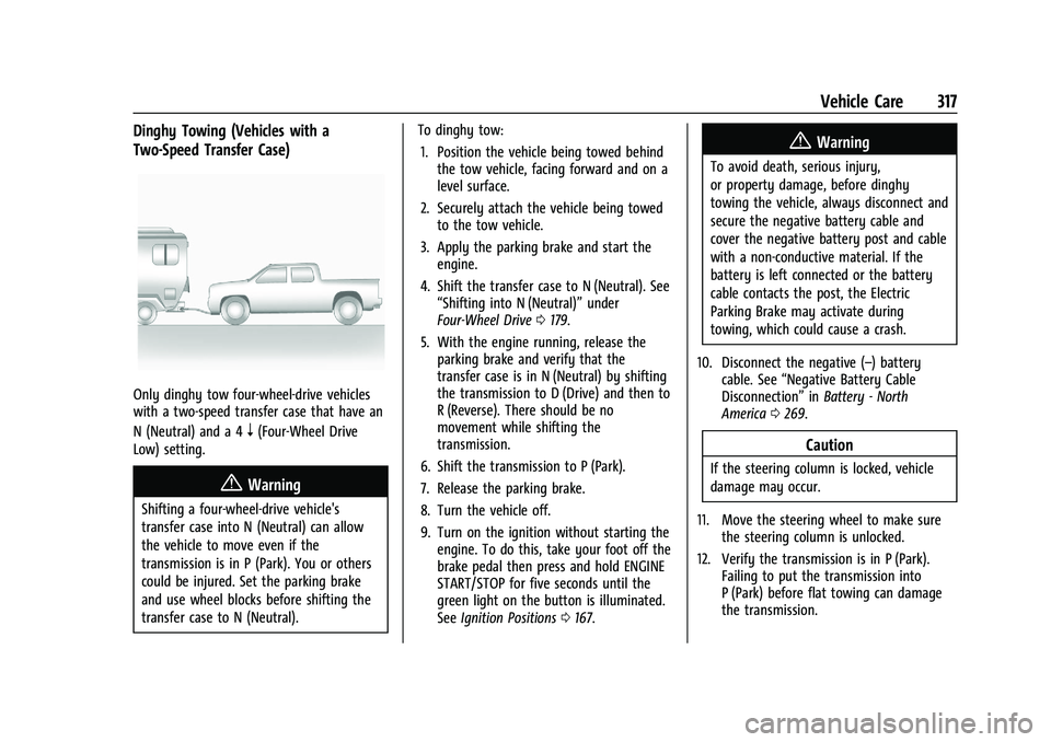
Only dinghy tow four-wheel-drive vehicles
with a two-speed transfer case that have an
N (Neutral) and a 4
n(Four-Wheel Drive
Low) setting.
{Warning
Shifting a four-wheel-drive vehicle's
transfer case into N (Neutral) can allow
the vehicle to move even if the
transmission is in P (Park). You or others
could be injured. Set the parking brake
and use wheel blocks before shifting the
transfer case to N (Neutral). To dinghy tow:
1. Position the vehicle being towed behind the tow vehicle, facing forward and on a
level surface.
2. Securely attach the vehicle being towed to the tow vehicle.
3. Apply the parking brake and start the engine.
4. Shift the transfer case to N (Neutral). See “Shifting into N (Neutral)” under
Four-Wheel Drive 0179.
5. With the engine running, release the parking brake and verify that the
transfer case is in N (Neutral) by shifting
the transmission to D (Drive) and then to
R (Reverse). There should be no
movement while shifting the
transmission.
6. Shift the transmission to P (Park).
7. Release the parking brake.
8. Turn the vehicle off.
9. Turn on the ignition without starting the engine. To do this, take your foot off the
brake pedal then press and hold ENGINE
START/STOP for five seconds until the
green light on the button is illuminated.
See Ignition Positions 0167.
{Warning
To avoid death, serious injury,
or property damage, before dinghy
towing the vehicle, always disconnect and
secure the negative battery cable and
cover the negative battery post and cable
with a non-conductive material. If the
battery is left connected or the battery
cable contacts the post, the Electric
Parking Brake may activate during
towing, which could cause a crash.
10. Disconnect the negative (–) battery cable. See “Negative Battery Cable
Disconnection” inBattery - North
America 0269.
Caution
If the steering column is locked, vehicle
damage may occur.
11. Move the steering wheel to make sure the steering column is unlocked.
12. Verify the transmission is in P (Park). Failing to put the transmission into
P (Park) before flat towing can damage
the transmission.