climate control GMC SAVANA PASSENGER 2009 Owners Manual
[x] Cancel search | Manufacturer: GMC, Model Year: 2009, Model line: SAVANA PASSENGER, Model: GMC SAVANA PASSENGER 2009Pages: 406, PDF Size: 2.34 MB
Page 1 of 406
Seats and Restraint System............................. 1-1
Front Seats
............................................... 1-2
Rear Seats
............................................... 1-6
Safety Belts
.............................................1-10
Child Restraints
.......................................1-31
Airbag System
.........................................1-58
Restraint System Check
............................1-79
Features and Controls..................................... 2-1
Keys
........................................................ 2-2
Doors and Locks
....................................... 2-6
Windows
.................................................2-13
Theft-Deterrent Systems
............................2-16
Starting and Operating Your Vehicle
...........2-18
Mirrors
....................................................2-31
Storage Areas
.........................................2-33
Instrument Panel............................................. 3-1
Instrument Panel Overview
.......................... 3-4
Climate Controls
......................................3-18
Warning Lights, Gages, and Indicators
........3-23
Driver Information Center (DIC)
..................3-41
Audio System(s)
.......................................3-64
Driving Your Vehicle....................................... 4-1
Your Driving, the Road, and the Vehicle
....... 4-2
Towing
...................................................4-24Service and Appearance Care.......................... 5-1
Service
..................................................... 5-3
Fuel
......................................................... 5-5
Checking Things Under the Hood
...............5-12
All-Wheel Drive
........................................5-45
Rear Axle
...............................................5-46
Front Axle
...............................................5-46
Noise Control System
...............................5-47
Bulb Replacement
....................................5-49
Windshield Wiper Blade Replacement
.........5-54
Tires
......................................................5-55
Appearance Care
.....................................5-96
Vehicle Identification
...............................5-103
Electrical System
....................................5-103
Capacities and Specifications
...................5-110
Maintenance Schedule..................................... 6-1
Maintenance Schedule
................................ 6-2
Customer Assistance Information.................... 7-1
Customer Assistance and Information
........... 7-2
Reporting Safety Defects
...........................7-15
Vehicle Data Recording and Privacy
...........7-17
Index................................................................ 1
2009 GMC Savana Owner ManualM
Page 117 of 406
Outside Convex Mirror
{CAUTION:
A convex mirror can make things (like other
vehicles) look farther away than they really are.
If you cut too sharply into the right lane, you
could hit a vehicle on the right. Check the inside
mirror or glance over your shoulder before
changing lanes.
The passenger side mirror is convex shaped. A convex
mirror’s surface is curved so more can be seen from
the driver seat.
Outside Heated Mirrors
For vehicles with heated mirrors:
<(Rear Defogger):Press to heat the mirrors.
An indicator light in the button lights when the outside
heated mirrors are activated.
See “Rear Window Defogger” underClimate Control
System on page 3-18for more information.
Storage Areas
Your vehicle may have a front storage compartment. It is
located at the center of the instrument panel extension,
by the floor. To open the compartment, pull up on the
latch. The compartment will open automatically.
Storage compartments may also be included on the
inside of each front door.
2-33
Page 119 of 406
Instrument Panel Overview...............................3-4
Hazard Warning Flashers................................3-6
Horn .............................................................3-6
Tilt Wheel.....................................................3-6
Turn Signal/Multifunction Lever.........................3-7
Turn and Lane-Change Signals........................3-7
Headlamp High/Low-Beam Changer..................3-8
Flash-to-Pass.................................................3-8
Windshield Wipers..........................................3-8
Windshield Washer.........................................3-9
Cruise Control................................................3-9
Exterior Lamps.............................................3-12
Headlamps on Reminder................................3-13
Daytime Running Lamps (DRL).......................3-14
Automatic Headlamp System..........................3-14
Instrument Panel Brightness...........................3-15
Dome Lamps ...............................................3-15
Dome Lamp Override....................................3-15
Entry/Exit Lighting.........................................3-16
Reading Lamps............................................3-16
Electric Power Management...........................3-16
Battery Run-Down Protection..........................3-17
Accessory Power Outlet(s).............................3-17
Ashtray(s) and Cigarette Lighter......................3-18Climate Controls............................................3-18
Climate Control System.................................3-18
Outlet Adjustment.........................................3-20
Rear Heating System....................................3-21
Rear Air Conditioning and Heating System.......3-22
Warning Lights, Gages, and Indicators............3-23
Instrument Panel Cluster................................3-24
Speedometer and Odometer...........................3-25
Trip Odometer..............................................3-25
Safety Belt Reminders...................................3-26
Airbag Readiness Light
..................................3-27
Airbag Off Light............................................3-28
Passenger Airbag Status Indicator...................3-29
Charging System Light..................................3-30
Voltmeter Gage............................................3-31
Brake System Warning Light..........................3-31
Antilock Brake System (ABS) Warning Light.....3-32
StabiliTrak
®Indicator Light.............................3-33
Engine Coolant Temperature Gage..................3-33
Tire Pressure Light.......................................3-34
Malfunction Indicator Lamp.............................3-34
Oil Pressure Gage........................................3-37
Oil Pressure Light.........................................3-38
Section 3 Instrument Panel
3-1
Page 123 of 406
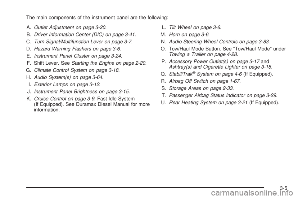
The main components of the instrument panel are the following:
A.Outlet Adjustment on page 3-20.
B.Driver Information Center (DIC) on page 3-41.
C.Turn Signal/Multifunction Lever on page 3-7.
D.Hazard Warning Flashers on page 3-6.
E.Instrument Panel Cluster on page 3-24.
F. Shift Lever. SeeStarting the Engine on page 2-20.
G.Climate Control System on page 3-18.
H.Audio System(s) on page 3-64.
I.Exterior Lamps on page 3-12.
J.Instrument Panel Brightness on page 3-15.
K.Cruise Control on page 3-9. Fast Idle System
(If Equipped). See Duramax Diesel Manual for more
information.L.Tilt Wheel on page 3-6.
M.Horn on page 3-6.
N.Audio Steering Wheel Controls on page 3-83.
O. Tow/Haul Mode Button. See “Tow/Haul Mode” under
Towing a Trailer on page 4-28.
P.Accessory Power Outlet(s) on page 3-17and
Ashtray(s) and Cigarette Lighter on page 3-18.
Q.StabiliTrak
®System on page 4-6(If Equipped).
R.Airbag Off Switch on page 1-67.
S.Storage Areas on page 2-33.
T.Passenger Airbag Status Indicator on page 3-29.
U.Rear Heating System on page 3-21(If Equipped).
3-5
Page 134 of 406
Entry/Exit Lighting
The vehicle has an illuminated entry/exit feature.
The dome lamps come on if the dome override button is
in the out position, when a door is opened or the key
is removed from the ignition.
Reading Lamps
For vehicles with reading lamps, press the button
located next to each lamp to turn it on or off.
The vehicle may also have reading lamps in other
locations. The lamps cannot be adjusted.
Electric Power Management
The vehicle has Electric Power Management (EPM) that
estimates the battery’s temperature and state of
charge. It then adjusts the voltage for best performance
and extended life of the battery.
When the battery’s state of charge is low, the voltage is
raised slightly to quickly bring the charge back up.
When the state of charge is high, the voltage is lowered
slightly to prevent overcharging. If the vehicle has a
voltmeter gage or a voltage display on the Driver
Information Center (DIC), you may see the voltage move
up or down. This is normal. If there is a problem, an
alert will be displayed.The battery can be discharged at idle if the electrical
loads are very high. This is true for all vehicles. This is
because the generator (alternator) may not be
spinning fast enough at idle to produce all the power
that is needed for very high electrical loads.
A high electrical load occurs when several of the
following are on, such as: headlamps, high beams, fog
lamps, rear window defogger, climate control fan at
high speed, heated seats, engine cooling fans, trailer
loads, and loads plugged into accessory power outlets.
EPM works to prevent excessive discharge of the
battery. It does this by balancing the generator’s output
and the vehicle’s electrical needs. It can increase
engine idle speed to generate more power, whenever
needed. It can temporarily reduce the power demands of
some accessories.
Normally, these actions occur in steps or levels, without
being noticeable. In rare cases at the highest levels of
corrective action, this action may be noticeable to the
driver. If so, a Driver Information Center (DIC) message
might be displayed, such as BATTERY SAVER ACTIVE,
BATTERY VOLTAGE LOW, or LOW BATTERY. If this
message is displayed, it is recommended that the driver
reduce the electrical loads as much as possible. SeeDIC
Warnings and Messages on page 3-48.
3-16
Page 136 of 406
Ashtray(s) and Cigarette Lighter
If your vehicle has this feature it is located in the center
console or on the instrument panel. Pull up on the
ashtray door to open it if it is in the console or pull the
door open it if it is on the instrument panel.
Notice:If papers, pins, or other �ammable items
are put in the ashtray, hot cigarettes or other
smoking materials could ignite them and possibly
damage the vehicle. Never put �ammable items
in the ashtray.
To remove the ashtray, pull it out from the console or
from the slide out door. To reinstall the ashtray,
slide it back to the original position.
To use the cigarette lighter, if the vehicle has one, push
it in all the way, and let go. When it is ready for use,
it will pop back out by itself.
Do not use the lighter to plug in accessory devices.
Use the power outlets provided.
Notice:Holding a cigarette lighter in while it is
heating does not let the lighter back away from the
heating element when it is hot. Damage from
overheating can occur to the lighter or heating
element, or a fuse could be blown. Do not hold a
cigarette lighter in while it is heating.
Climate Controls
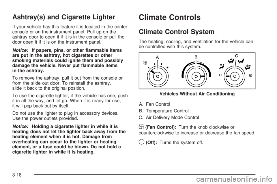
Climate Control System
The heating, cooling, and ventilation for the vehicle can
be controlled with this system.
A. Fan Control
B. Temperature Control
C. Air Delivery Mode Control
9(Fan Control):Turn the knob clockwise or
counterclockwise to increase or decrease the fan speed.
9(Off):Turns the system off. Vehicles Without Air Conditioning
3-18
Page 139 of 406
Rear Heating System
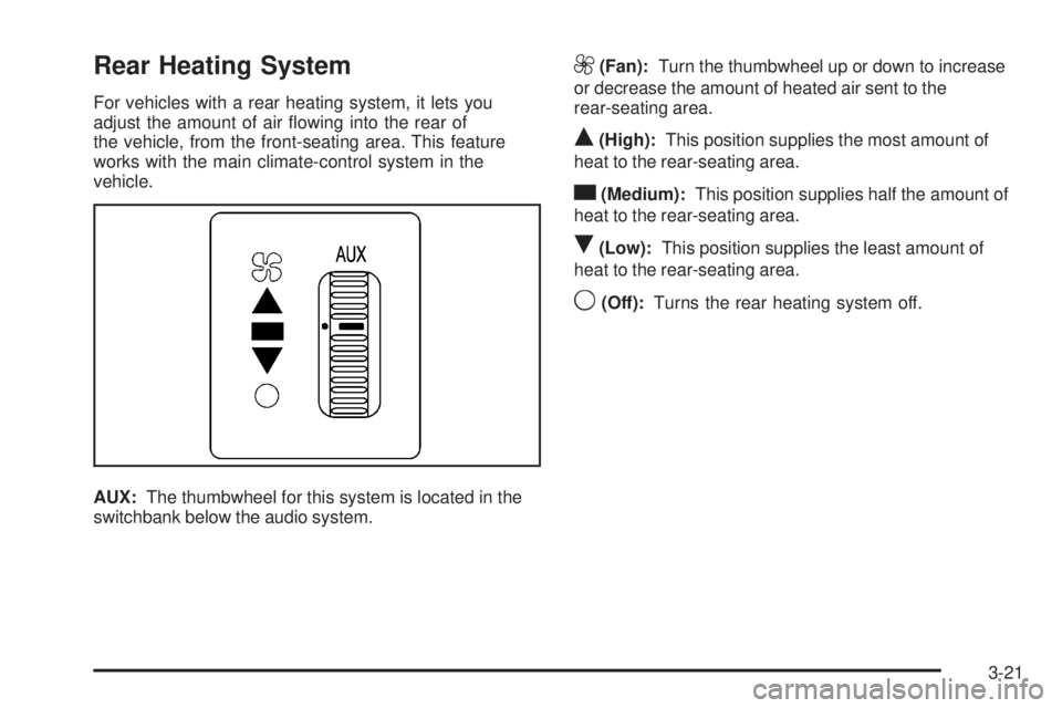
For vehicles with a rear heating system, it lets you
adjust the amount of air flowing into the rear of
the vehicle, from the front-seating area. This feature
works with the main climate-control system in the
vehicle.
AUX:The thumbwheel for this system is located in the
switchbank below the audio system.
9(Fan):Turn the thumbwheel up or down to increase
or decrease the amount of heated air sent to the
rear-seating area.
Q(High):This position supplies the most amount of
heat to the rear-seating area.
c(Medium):This position supplies half the amount of
heat to the rear-seating area.
R(Low):This position supplies the least amount of
heat to the rear-seating area.
9(Off):Turns the rear heating system off.
3-21
Page 140 of 406
Rear Air Conditioning and Heating
System
For vehicles with a rear heating and air-conditioning
system, it maintains the temperature, fan speed and air
delivery for the rear-seat passengers only. It also
works with the main climate-control system in the
vehicle.
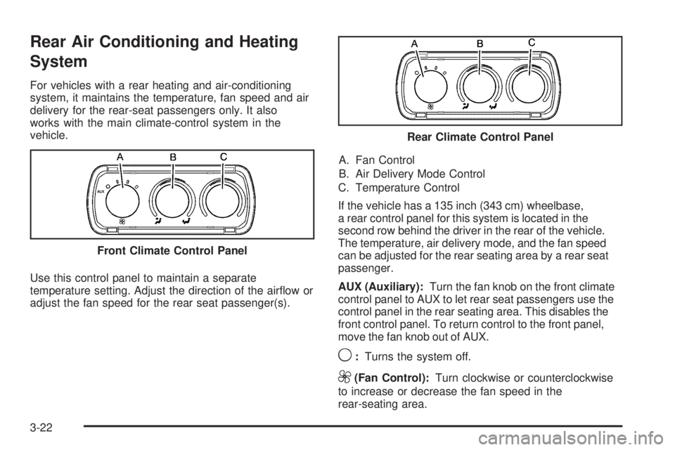
Use this control panel to maintain a separate
temperature setting. Adjust the direction of the airflow or
adjust the fan speed for the rear seat passenger(s).A. Fan Control
B. Air Delivery Mode Control
C. Temperature Control
If the vehicle has a 135 inch (343 cm) wheelbase,
a rear control panel for this system is located in the
second row behind the driver in the rear of the vehicle.
The temperature, air delivery mode, and the fan speed
can be adjusted for the rear seating area by a rear seat
passenger.
AUX (Auxiliary):Turn the fan knob on the front climate
control panel to AUX to let rear seat passengers use the
control panel in the rear seating area. This disables the
front control panel. To return control to the front panel,
move the fan knob out of AUX.
9:Turns the system off.
9(Fan Control):Turn clockwise or counterclockwise
to increase or decrease the fan speed in the
rear-seating area. Front Climate Control Panel
Rear Climate Control Panel
3-22
Page 141 of 406
Temperature Control:Turn clockwise or
counterclockwise to increase or decrease the
temperature in the rear-seating area.
The air-conditioning system on the main climate control
panel must be turned on to direct cooled air to the
rear of the vehicle. If it is not on, then the temperature
in the rear of the vehicle remains at cabin temperature.
Air Delivery Mode Control:Turn clockwise or
counterclockwise to change the direction of the airflow
in the rear seating area.
To change the current mode, select one of the following:
H(Vent):Air is directed to the upper outlets, with
some directed to the floor outlets.
2(Floor):Air is directed to the floor outlets.
Be sure to keep the area under the front seats clear of
any objects so that the air inside of the vehicle can
circulate effectively.
For information on how to use the main climate control
system, seeClimate Control System on page 3-18.
For information on ventilation, seeOutlet Adjustment on
page 3-20.
Warning Lights, Gages, and
Indicators
Warning lights and gages can signal that something is
wrong before it becomes serious enough to cause
an expensive repair or replacement. Paying attention to
the warning lights and gages could prevent injury.
Warning lights come on when there may be or is a
problem with one of the vehicle’s functions. Some
warning lights come on briefly when the engine is started
to indicate they are working.
Gages can indicate when there may be or is a problem
with one of the vehicle’s functions. Often gages and
warning lights work together to indicate a problem with
the vehicle.
When one of the warning lights comes on and stays on
while driving, or when one of the gages shows there
may be a problem, check the section that explains what
to do. Follow this manual’s advice. Waiting to do
repairs can be costly and even dangerous.
3-23
Page 166 of 406
To calibrate the compass, use the following procedure:
Compass Calibration Procedure
1. Before calibrating the compass, make sure the
compass zone is set to the variance zone in
which the vehicle is located. See “Compass
Variance (Zone) Procedure” earlier in this section.
Do not operate any switches such as window,
sunroof, climate controls, seats, etc. during
the calibration procedure.
2. Press the vehicle information button until
PRESS
VTO CALIBRATE COMPASS displays.
3. Press the set/reset button to start the compass
calibration.
4. The DIC will display CALIBRATING: DRIVE IN
CIRCLES. Drive the vehicle in tight circles at
less than 5 mph (8 km/h) to complete the calibration.
The DIC will display CALIBRATION COMPLETE
for a few seconds when the calibration is complete.
The DIC display will then return to PRESS
VTO
CALIBRATE COMPASS.
DIC Warnings and Messages
Messages are displayed on the DIC to notify the driver
that the status of the vehicle has changed and that
some action may be needed by the driver to correct the
condition. Multiple messages may appear one after
another.
Some messages may not require immediate action, but
you can press any of the DIC buttons on the instrument
panel to acknowledge that you received the messages
and to clear them from the display.
Some messages cannot be cleared from the DIC
display because they are more urgent. These messages
require action before they can be cleared. You should
take any messages that appear on the display seriously
and remember that clearing the messages will only
make the messages disappear, not correct the problem.
The following are the possible messages that can be
displayed and some information about them.
If your vehicle has the DURAMAX
®Diesel engine, see
the DURAMAX®Diesel manual for more information.
3-48