remote start GMC SIERRA 2009 Owner's Guide
[x] Cancel search | Manufacturer: GMC, Model Year: 2009, Model line: SIERRA, Model: GMC SIERRA 2009Pages: 596, PDF Size: 3.25 MB
Page 456 of 596
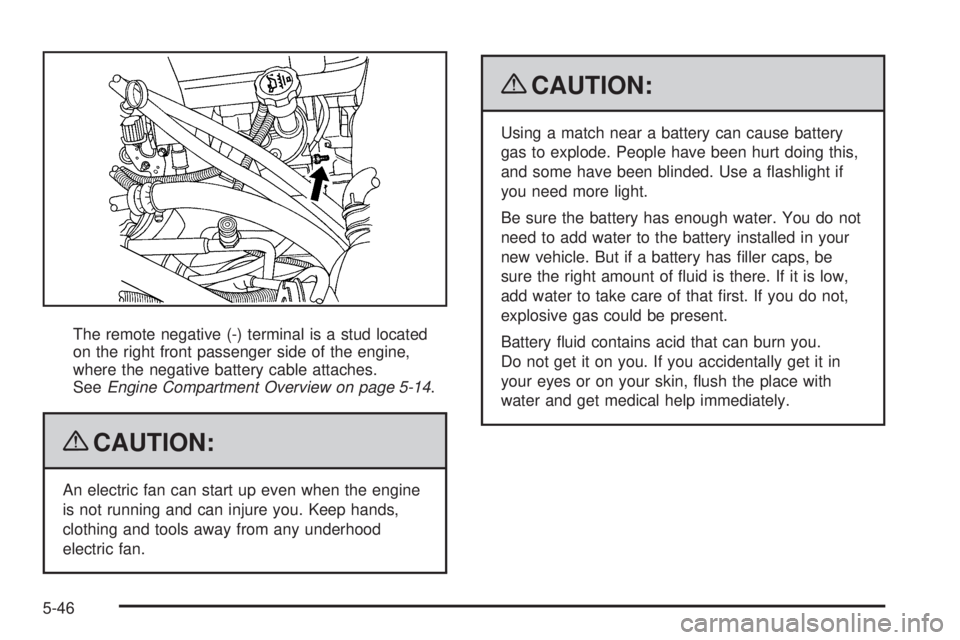
The remote negative (-) terminal is a stud located
on the right front passenger side of the engine,
where the negative battery cable attaches.
SeeEngine Compartment Overview on page 5-14.
{CAUTION:
An electric fan can start up even when the engine
is not running and can injure you. Keep hands,
clothing and tools away from any underhood
electric fan.
{CAUTION:
Using a match near a battery can cause battery
gas to explode. People have been hurt doing this,
and some have been blinded. Use a �ashlight if
you need more light.
Be sure the battery has enough water. You do not
need to add water to the battery installed in your
new vehicle. But if a battery has �ller caps, be
sure the right amount of �uid is there. If it is low,
add water to take care of that �rst. If you do not,
explosive gas could be present.
Battery �uid contains acid that can burn you.
Do not get it on you. If you accidentally get it in
your eyes or on your skin, �ush the place with
water and get medical help immediately.
5-46
Page 458 of 596
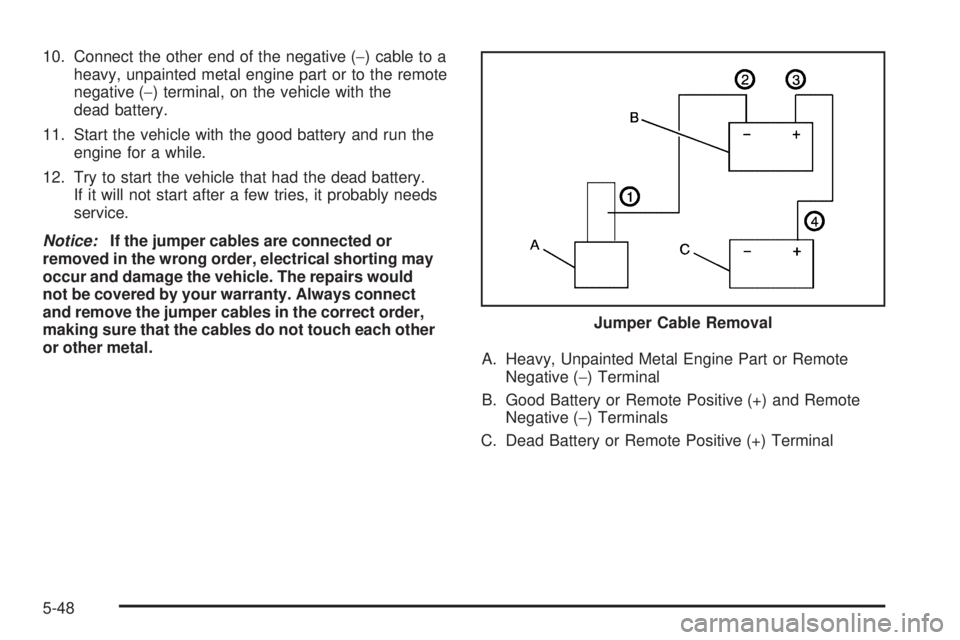
10. Connect the other end of the negative (−) cable to a
heavy, unpainted metal engine part or to the remote
negative (−) terminal, on the vehicle with the
dead battery.
11. Start the vehicle with the good battery and run the
engine for a while.
12. Try to start the vehicle that had the dead battery.
If it will not start after a few tries, it probably needs
service.
Notice:If the jumper cables are connected or
removed in the wrong order, electrical shorting may
occur and damage the vehicle. The repairs would
not be covered by your warranty. Always connect
and remove the jumper cables in the correct order,
making sure that the cables do not touch each other
or other metal.
A. Heavy, Unpainted Metal Engine Part or Remote
Negative (−) Terminal
B. Good Battery or Remote Positive (+) and Remote
Negative (−) Terminals
C. Dead Battery or Remote Positive (+) TerminalJumper Cable Removal
5-48
Page 490 of 596
The TPMS sensor matching process is outlined below:
1. Set the parking brake.
2. Turn the ignition switch to ON/RUN with the
engine off.
3. Press the Remote Keyless Entry (RKE) transmitter’s
LOCK and UNLOCK buttons at the same time for
approximately �ve seconds. The horn sounds twice
to signal the receiver is in relearn mode and TIRE
LEARNING ACTIVE message displays on the DIC
screen.
If your vehicle does not have RKE, press the Driver
Information Center (DIC) vehicle information button
until the PRESS
VTO RELEARN TIRE POSITIONS
message displays. The horn sounds twice to signal
the receiver is in relearn mode and TIRE LEARNING
ACTIVE message displays on the DIC screen.
If your vehicle does not have RKE or DIC buttons,
press the trip odometer reset stem located on the
instrument panel cluster until the PRESS
VTO
RELEARN TIRE POSITIONS message displays.
The horn sounds twice to signal the receiver is in
relearn mode and TIRE LEARNING ACTIVE
message displays on the DIC screen.
4. Start with the driver side front tire.5. Remove the valve cap from the valve cap stem.
Activate the TPMS sensor by increasing or
decreasing the tire’s air pressure for �ve seconds,
or until a horn chirp sounds. The horn chirp,
which may take up to 30 seconds to sound,
con�rms that the sensor identi�cation code has
been matched to this tire and wheel position.
6. Proceed to the passenger side front tire, and repeat
the procedure in Step 5.
7. Proceed to the passenger side rear tire, and repeat
the procedure in Step 5.
8. Proceed to the driver side rear tire, and repeat the
procedure in Step 5. The horn sounds two times to
indicate the sensor identi�cation code has been
matched to the driver side rear tire, and that the
TPMS sensor matching process is no longer active.
The TIRE LEARNING ACTIVE message on the DIC
display screen goes off.
9. Turn the ignition switch to LOCK/OFF.
10. Set all four tires to the recommended air pressure
level as indicated on the Tire and Loading
Information label.
11. Put the valve caps back on the valve stems.
5-80
Page 572 of 596
Coverage
Services are provided up to 5 years/100,000 miles
(160 000 km), whichever comes �rst.
In the U.S., anyone driving the vehicle is covered.
In Canada, a person driving the vehicle without
permission from the owner is not covered.
Roadside Assistance is not a part of the New Vehicle
Limited Warranty. GMC and General Motors of Canada
Limited reserve the right to make any changes or
discontinue the Roadside Assistance program at any
time without noti�cation.
GMC and General Motors of Canada Limited reserve
the right to limit services or payment to an owner
or driver if they decide the claims are made too often, or
the same type of claim is made many times.
Services Provided
Emergency Fuel Delivery:Delivery of enough fuel
for the vehicle to get to the nearest service station.
Lock-Out Service:Service is provided to unlock the
vehicle if you are locked out. A remote unlock may
be available if you have OnStar
®. For security
reasons, the driver must present identi�cation
before this service is given.
Emergency Tow From a Public Road or Highway:
Tow to the nearest GMC dealer for warranty service,
or if the vehicle was in a crash and cannot be driven.
Assistance is also given when the vehicle is stuck in
the sand, mud, or snow.
Flat Tire Change:Service is provided to change a
�at tire with the spare tire. The spare tire, if equipped,
must be in good condition and properly in�ated.
It is the owner’s responsibility for the repair or
replacement of the tire if it is not covered by the
warranty.
Battery Jump Start:Service is provided to jump
start a dead battery.
Trip Routing Service:Detailed maps of North
America are provided when requested either with
the most direct route or the most scenic route.
Additional travel information is also available.
Allow three weeks for delivery.
Trip Interruption Bene�ts and Assistance:If your
trip is interrupted due to a warranty failure, incidental
expenses may be reimbursed during the 5 years/
100,000 miles (160 000 km) Powertrain warranty
period. Items considered are hotel, meals, and
rental car.
7-8
Page 582 of 596
OnStar®
If your vehicle has OnStar and you subscribe to the
OnStar services, please refer to the OnStar Terms
and Conditions for information on data collection and
use. See alsoOnStar
®System on page 2-71in
this manual for more information.
Navigation System
If your vehicle has a navigation system, use of the
system may result in the storage of destinations,
addresses, telephone numbers, and other trip
information. Refer to the navigation system operating
manual for information on stored data and for deletion
instructions.
Radio Frequency
Identi�cation (RFID)
RFID technology is used in some vehicles for functions
such as tire pressure monitoring and ignition system
security, as well as in connection with conveniences
such as key fobs for remote door locking/unlocking and
starting, and in-vehicle transmitters for garage door
openers. RFID technology in GM vehicles does not use
or record personal information or link with any other
GM system containing personal information.
7-18
Page 593 of 596
Recreational Vehicle Towing.............................4-45
Remote Keyless Entry (RKE) System.................. 2-4
Remote Keyless Entry (RKE) System,
Operation..................................................... 2-5
Remote Vehicle Start........................................ 2-7
Removing the Flat Tire and Installing the
Spare Tire..................................................5-98
Removing the Spare Tire and Tools...................5-93
Replacement Bulbs.........................................5-63
Replacement Parts, Maintenance......................6-17
Reporting Safety Defects
Canadian Government..................................7-15
General Motors...........................................7-15
United States Government............................7-14
Restraint System Check
Checking the Restraint Systems....................1-90
Replacing Restraint System Parts
After a Crash..........................................1-91
Retained Accessory Power...............................2-23
Roadside
Assistance Program....................................... 7-7
Rocking Your Vehicle to Get it Out....................4-30
Routing, Engine Drive Belt...............................6-18
Running the Vehicle While Parked.....................2-56S
Safety Belt Reminders.....................................3-36
Safety Belts
Care of ....................................................5-116
How to Wear Safety Belts Properly................1-21
Lap Belt.....................................................1-36
Lap-Shoulder Belt........................................1-30
Safety Belt Extender....................................1-37
Safety Belt Use During Pregnancy.................1-36
Safety Belts Are for Everyone.......................1-16
Safety Warnings and Symbols.............................. iii
Scheduled Maintenance..................................... 6-4
Seatback Latches...........................................1-13
Seats
Center Seat................................................1-14
Heated Seats............................................... 1-8
Manual Lumbar............................................. 1-6
Memory, Mirrors and Pedals........................... 1-8
Power Lumbar .............................................. 1-7
Power Seats................................................. 1-5
Rear Seat Operation............................1-14, 1-15
Reclining Seatbacks.....................................1-10
Seatback Latches........................................1-13
Secondary Latch System................................5-106
Securing a Child Restraint
Center Front Seat Position............................1-61
Rear Seat Position......................................1-58
Right Front Seat Position..............1-62, 1-66, 1-70
11
Page 594 of 596
Security Light.................................................3-50
Service........................................................... 5-4
Accessories and Modi�cations......................... 5-4
Adding Equipment to the Outside of
the Vehicle................................................ 5-6
California Perchlorate Materials
Requirements............................................ 5-5
California Proposition 65 Warning.................... 5-5
Doing Your Own Work................................... 5-5
Engine Soon Lamp......................................3-45
Publications Ordering Information...................7-15
Service, Scheduling Appointments.....................7-10
Servicing Your Airbag-Equipped Vehicle..............1-88
Setting the Clock............................................3-86
Sheet Metal Damage.....................................5-120
Shifting Into Park............................................2-52
Shifting Out of Park........................................2-54
Signals, Turn and Lane-Change.......................... 3-9
Sliding Rear Window, Power.............................2-17
Snow Plow....................................................4-38
Spare Tire....................................................5-113
Installing....................................................5-98
Removing...................................................5-93
Storing.....................................................5-109
Speci�cations, Capacities...............................5-129
Speedometer..................................................3-35
StabiliTrak
®Indicator Light...............................3-44
StabiliTrak®System.......................................... 4-6
Start Vehicle, Remote....................................... 2-7
Starting the Engine.........................................2-24Steering.......................................................... 4-9
Steering Wheel Controls, Audio.......................3-141
Steering Wheel, Tilt Wheel................................. 3-8
Storage Areas
Cargo Management System..........................2-84
Center Console Storage Area........................2-82
Cupholders.................................................2-81
Glove Box..................................................2-81
Instrument Panel Storage Area......................2-81
Luggage Carrier..........................................2-82
Rear Seat Armrest.......................................2-83
Stuck in Sand, Mud, Ice, or Snow.....................4-30
Sun Visors.....................................................2-18
Sunroof.........................................................2-85
T
Tachometer....................................................3-35
Tailgate.........................................................2-13
Taillamps
Turn Signal, Stoplamps and
Back-up Lamps........................................5-61
Theft-Deterrent, Radio....................................3-140
Theft-Deterrent Systems...................................2-18
Content Theft-Deterrent................................2-18
PASS-Key
®III+ Electronic Immobilizer............2-20
PASS-Key®III+ Electronic Immobilizer
Operation................................................2-20
Tilt Wheel........................................................ 3-8
12
Page 596 of 596
V
Vehicle
Control........................................................ 4-3
Loading......................................................4-32
Running While Parked..................................2-56
Symbols......................................................... iii
Vehicle Customization, DIC..............................3-76
Vehicle Data Recording and Privacy..................7-16
Vehicle Identi�cation
Number (VIN)............................................5-121
Service Parts Identi�cation Label..................5-121
Vehicle, Remote Start....................................... 2-7
Ventilation Adjustment......................................3-33
Visors...........................................................2-18
Voltmeter Gage..............................................3-41
W
Warning Lights, Gages, and Indicators...............3-33
Warnings
DIC Warnings and Messages........................3-66
Hazard Warning Flashers............................... 3-8
Safety and Symbols......................................... iii
Wheels
Alignment and Tire Balance..........................5-88
Different Size..............................................5-86
Replacement...............................................5-89Where to Put the Restraint...............................1-48
Windows.......................................................2-15
Manual......................................................2-16
Power ........................................................2-16
Sliding Rear................................................2-17
Windshield
Rainsense™ II Wipers..................................3-11
Washer......................................................3-12
Washer Fluid..............................................5-39
Wiper Blade Replacement.............................5-64
Wiper Blades, Cleaning..............................5-118
Wiper Fuses.............................................5-122
Wipers.......................................................3-10
Winter Driving................................................4-28
X
XM Radio Messages.....................................3-118
XM™ Satellite Radio Antenna System..............3-142
Y
Your Vehicle and the Environment....................... 6-2
14