fuses GMC SIERRA DENALI 2003 Owners Manual
[x] Cancel search | Manufacturer: GMC, Model Year: 2003, Model line: SIERRA DENALI, Model: GMC SIERRA DENALI 2003Pages: 428, PDF Size: 20.35 MB
Page 95 of 428
Here’s how to avoid setting off the alarm by accident:
If you don’t want to activate the theft-deterrent
system, the vehicle should be locked with the door
key after the doors are closed.
Always unlock a door with a key, or use the remote
keyless entry transmitter. Unlocking a door any
other way will set
off the alarm if the system
has been armed.
If you set off the alarm by accident, unlock any door
with the key. You can also turn
off the alarm by pressing
UNLOCK on the remote keyless entry transmitter or
by placing the key in the ignition and turning it to
START.
Testing the Alarm
The alarm can be tested by following these steps:
1. From inside the vehicle, lower the driver’s window
and open the driver’s door.
2. Activate the system by locking the doors with the
power door lock switch while the door is open, or
with the remote keyless entry transmitter.
3. Get out of the vehicle, close the door and wait for
the security message
to go out.
4. Then reach in through the window, unlock the door
with the manual door lock and open the door. This
should set
off the alarm. If the
alarm does not sound and the headlamps do not
flash, you may have the feature turned
off. See DIC
Operation and Displays on page 3-43 for more
information.
Passlock@
Your vehicle is equipped with the
Passlock@ theft-deterrent system.
Passlock@ is a passive theft-deterrent system.
Passlock@ enables fuel
if the ignition lock cylinder is
turned with a valid key.
If a correct key is not used or the
ignition lock cylinder is tampered with, fuel is disabled.
If the engine stalls and the security light flashes,
wait until the light stops flashing before trying to restart
the engine. Remember
to release the key from
START as soon as the engine starts.
If the engine is running and the security light comes on,
you will be able
to restart the engine if you turn the
engine
off. However, your Passlock@ system is
not working properly and must be serviced by your
dealer. Your vehicle is not protected by Passlock@ at this
time. You may also want to check the fuse (see
Fuses and Circuit Breakers on page 5-95.) See your
dealer for service.
In an emergency, call the GM Roadside Assistance
Center. See
Roadside Assistance Program on page 7-5
under Customer Assistance Information.
2-1 4
Page 99 of 428
To Use the Engine Coolant Heater
1. Turn off the engine.
2. Open the hood and unwrap the electrical cord. The
cord is located on the driver’s side of the engine
compartment, near the power steering fluid
reservoir. If you have a diesel engine, refer to
diesel supplement for location.
3. Plug it into a normal, grounded 11 0-volt AC outlet.
Plugging the cord into an ungrounded outlet
could cause an electrical shock. Also, the
wrong kind of extension cord could overheat
and cause a fire. You could
be seriously
injured. Plug the cord into a properly grounded
three-prong
11 0-volt AC outlet. If the cord
won’t reach, use a heavy-duty three-prong
extension cord rated for at least
15 amps.
4. Before starting the engine, be sure to unplug ana
store the cord as it was before to keep it away
from moving engine parts.
If you don’t, it could be
damaged.
How long should you keep the coolant heater plugged
in? The answer depends on the outside temperature, the
kind of oil you have, and some other things. Instead
of trying to list everything here, we ask that you contact
your dealer in the area where you’ll be parking your
vehicle. The dealer can give you the best advice for that
particular area.
Automatic Transmission Operation
Your vehicle is equipped with an automatic transmission
that features an electronic shift position indicator
located within the instrument panel cluster. This display
is powered anytime the shift lever
is capable of being
moved out
of PARK (P). See Fuses and Circuit Breakers
on page
5-95.
There are several different positions for your shift lever.
PARK
(P): This position locks your wheels. It’s the
best position to use when you start your engine because
your vehicle can’t move easily.
2-1 8
Page 130 of 428
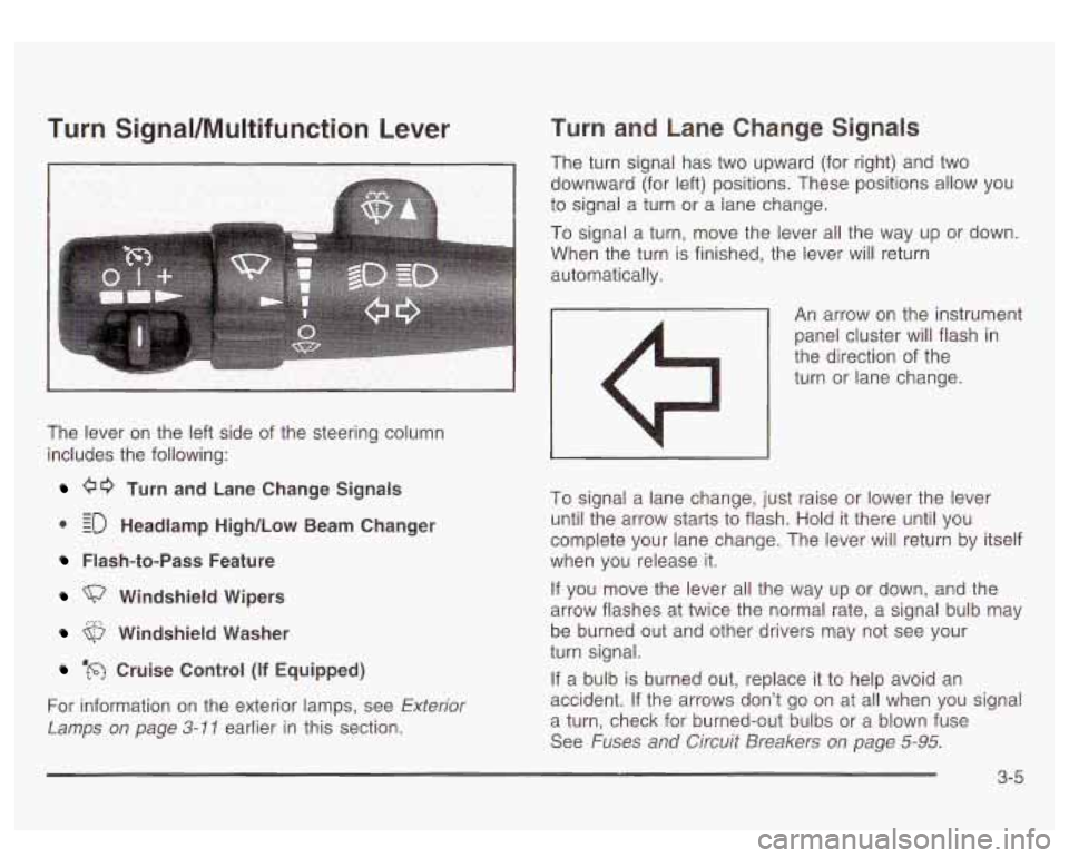
Turn SignaVMultifunction Lever
The lever on the left side of the steering column
includes the following:
00 Turn and Lane Change Signals
0 EO Headlamp High/Low Beam Changer
- -
Flash-to-Pass Feature
Windshield Wipers
Windshield Washer
‘m Cruise Control (if Equipped)
For information on the exterior lamps, see
Exterior
Lamps on page 3-11 earlier in this section.
Turn and Lane Change Signals
The turn signal has two upward (for right) and two
downward (for left) positions. These positions allow you
to signai a turn or a lane change.
To signal a turn, move the lever all the way up or down.
When the turn is finished, the lever will return
automatically.
An arrow on the instrument
panel cluster will flash
in
the direction of the
turn or lane change.
To signal a lane change, just raise or lower the lever
until the arrow starts to flash. Hold it there until you
complete your lane change. The lever will return by itself
when you release it.
If you move the lever all the way up or down, and the
arrow flashes at twice the normal rate, a signal bulb may
be burned out and other drivers may not see your
turn signal.
If a bulb
is burned out, replace it to help avoid an
accident. If the arrows don’t
go on at all when you signal
a turn, check for burned-out bulbs or a blown fuse
See
Fuses and Circuit Breakers on page 5-95.
3-5
Page 142 of 428
Certain electrical accessories may not be compatible
with the accessory power outlets and could result
in blown vehicle or adapter fuses.
If you experience a
problem, see your dealer for additional information
on accessory power outlets.
Notice: Adding some electrical equipment to your
vehicle can damage
it or keep other things from
working
as they should. This wouldn’t be covered by
your warranty. Check with your dealer before
adding electrical equipment, and never use anything
that exceeds the amperage rating.
When adding electrical equipment, be sure to follow the
proper installation instructions included with the
equipment.
Notice: Power outlets are designed for accessory
plugs only. Do not hang any type of accessory
or accessory bracket from the plug. Improper use of
the power outlet can cause damage not covered by your warranty.
Ashtrays and Cigarette Lighter
The ashtray is located in the center console. Press the
raised area on the access door to use the ashtray.
To remove the ashtray first locate the indent on the right
side of the ashtray. Then, place an instrument, such
as a pen, in the indent and pry the ashtray out.
Notice: Don’t put papers or other flammable items
into your ashtrays. Hot cigarettes or other smoking
materials could ignite them, causing a damaging fire.
To use the cigarette lighter, push it in all the way, and
let go. When it’s ready, it will pop back out by itself.
Notice: Don’t hold a cigarette lighter
in with your
hand while
it is heating. If you do, it won’t be able to
back away from the heating element when
it’s
ready. That can make it overheat, damaging the
lighter and the heating element.
3-1 7
Page 271 of 428
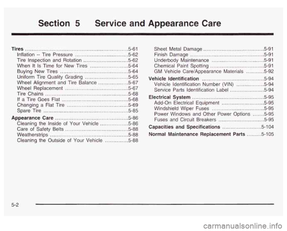
Section 5 Service and Appearance Care
Tires .......................................................... 5-61
Inflation
.. Tire Pressure ................................ 5.62
Tire Inspection and Rotation
........................... 5.62
When It
Is Time for New Tires ....................... 5-64
Buying New Tires
......................................... 5-64
Uniform Tire Quality Grading
.......................... 5-65
Wheel Alignment and Tire Balance
.................. 5.67
Wheel Replacement
...................................... 5.67
Tire Chains
.................................................. 5-68
If a Tire Goes Flat ........................................ 5.68
Spare Tire
................................................... 5.85
Changing a
Flat Tire
.................. ............ 5.69
Appearance Care
............................................ 5.86
Cleaning the Inside of Your Vehicle
................. 5-86
Care of Safety Belts
...................................... 5-88
Weatherstrips
........................................... 5-88
Cleaning the Outside of Your Vehicle
.. .... 5-88
Sheet Metal Damage ..................................... 5-91
Underbody Maintenance
................................ 5-91
Chemical Paint Spotting
............................... -591
Vehicle Identification
...................................... 5-94
Vehicle Identification Number (VIN)
................. 5-94
Service Parts Identification Label
..................... 5-94
Electrical System
............................................ 5-95
Add-on Electrical Equipment
.......................... 5-95
Windshield Wiper Fuses
................................ 5-95
Fuses and Circuit Breakers
............................ 5-95
Capacities and Specifications
........................ 5-104
Normal Maintenance Replacement Parts
......... 5-105
Finish
Damage
............................................. 5-91
GM Vehicle Care/Appearance Materials
........... 5-92
Power Windows and Other Power Options
....... 5-95
5-2
Page 364 of 428
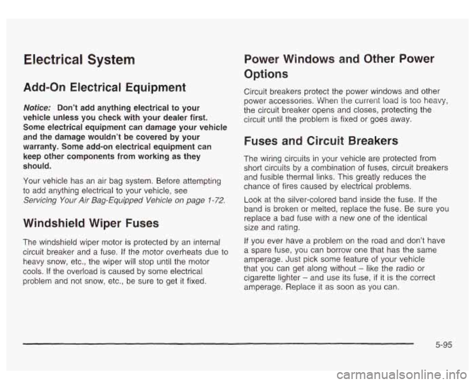
Electrical System
Add-on Electrical Equipment
Notice: Don’t add anything electrical to your
vehicle unless you check with your dealer first.
Some electrical equipment can damage your vehicle
and the damage wouldn’t be covered by your
warranty. Some add-on electrical equipment can
keep other components from working as they
should.
Your vehicle has an air bag system. Before attempting
to add anything electrical to your vehicle, see
Servicing Your Air Bag-Equipped Vehicle on page 1-72.
Windshield Wiper Fuses
The windshield wiper motor is protected by an internal
circuit breaker and a fuse.
If the motor overheats due to
heavy snow, etc., the wiper will stop until the motor
cools. If the overload
is caused by some electrical
problem and not snow, etc., be sure to get it fixed.
Power Windows and Other Power
Options
Circuit breakers protect the power windows and other
power accessories. When the current load
is too heavy,
the circuit breaker opens and closes, protecting the
circuit until the problem is fixed or goes away.
Fuses and Circuit Breakers
The wiring circuits in your vehicle are protected from
short circuits by a combination of fuses, circuit breakers
and fusible thermal links. This greatly reduces the
chance of fires caused by electrical problems.
Look at the silver-colored band inside the fuse. If the
band is broken or melted, replace the fuse. Be sure you
replace a bad fuse with a new one
of the identical
size and rating.
If you ever have a problem on the road and don’t have
a spare fuse, you can borrow one that has the same
amperage. Just pick some feature of your vehicle
that you can get along without
- like the radio or
cigarette lighter - and use its fuse, if it is the correct
amperage. Replace it as soon as you can.
5-95
Page 365 of 428
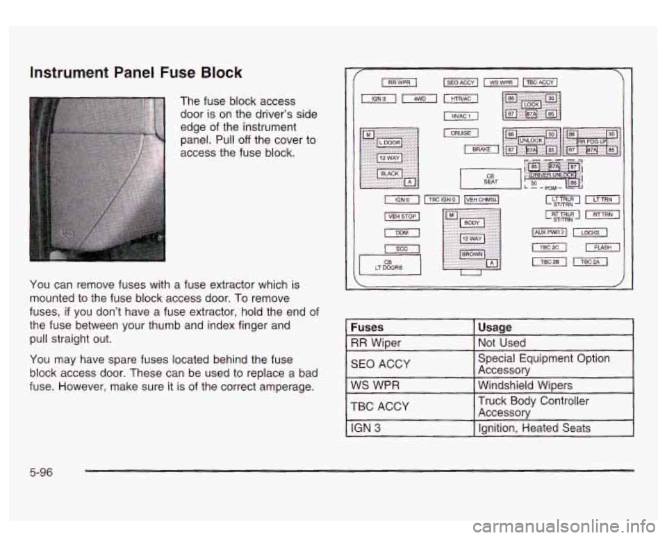
Instrument Panel Fuse Block
The fuse block access
door is on the driver's side
edge of the instrument
panel. Pull
off the cover to
access the fuse block.
You can remove fuses with a fuse extractor which
is
mounted to the fuse block access door. To remove
fuses,
if you don't have a fuse extractor, hold the end of
the fuse between your thumb and index finger and
pull straight out.
You may have spare fuses located behind the fuse
block access door. These can be used to replace
a bad
fuse. However, make sure it is of the correct amperage.
II
LT DOORS U
Fuses
SEO ACCY Not
Used
RR Wiper
Usage
TBC
ACCY Windshield Wipers
WS
WPR Accessory
Special Equipment Option
Ignition, Heated Seats
IGN 3
Accessory Truck Body Controller
5-96
Page 366 of 428
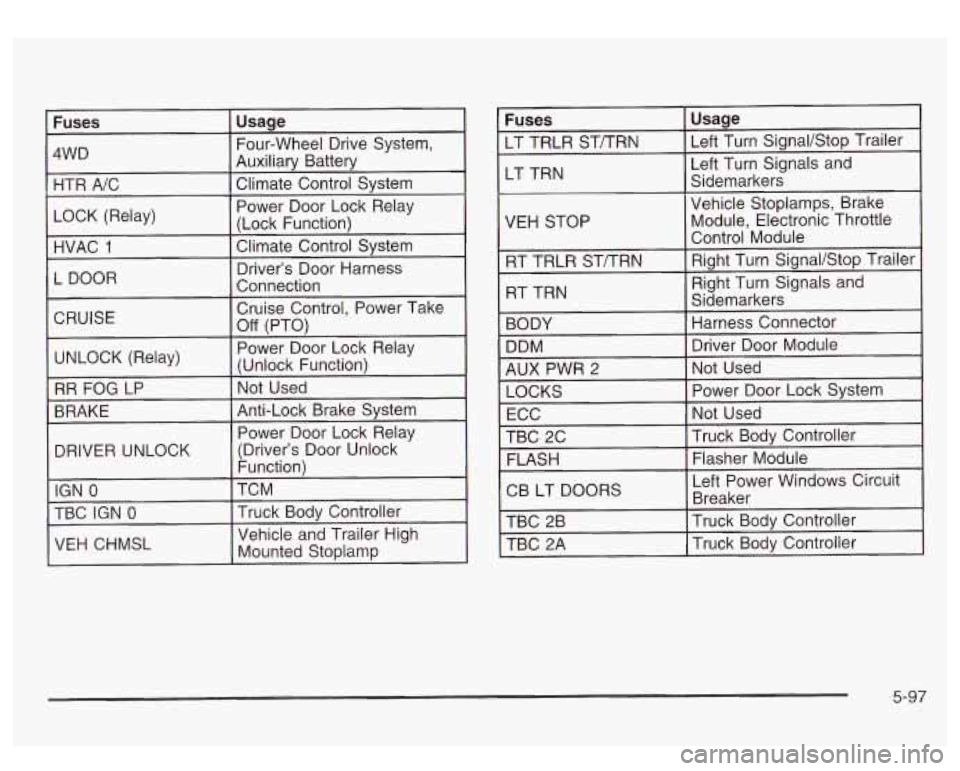
DRIVER UNLOCK
Fuses Usage
LT TRLR ST/TRN Left Turn SignaVStop Trailer
LT TRN Left Turn Signals
and
Sidemarkers
VEH STOP
5-97
Page 368 of 428
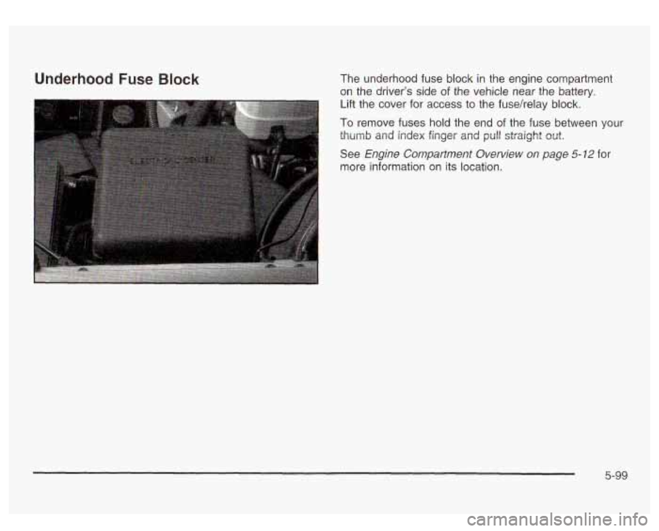
Underhood Fuse Block The underhood fuse block in the engine compartment
on the driver's side of the vehicle near the battery.
Lift the cover for access to the fusehelay block.
To remove fuses hold the end of the fuse between your
thumb and
index finger and pull straight out.
See
Engine Compartment Overview on page 5-12 for
more information on its location.
5-99
Page 369 of 428
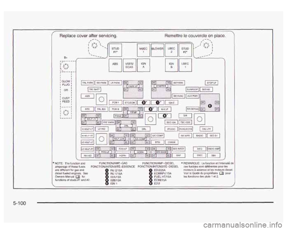
Replace cover after servicing. Remettre le couvercle en place.
I ? i I I I I I
I
I I I
I
I I I L I 1 I I L
B+
GLOW I PLUG
OR I
I CUST I FEED I I -_--l
NOTE: The function and FUNCTION/AMy-GAS
amperage of these fuses FONCTION/INTENSIT!-ESSENCE FONCTIONIINTENSITE-DIESEL ces fusibles sont diffbrentes pour les
FUNCTION/AMP-QlESEL * REMARQUE: La fonction
et I'intensitk de
are different for gas and INJ 2/15A EDU/25A moteurs essence et les rnoteurs diesel.
diesel fueled engines. See
Owners Manual for
functions
of studs #I and #2. ECMV15A f
tCMRPV/I5A
FUEL HT/15A Voir le Guide du propri6taire a pour
les fonctions des plots 1 et 2.
5- 1 00