GMC SONOMA 2004 Owner's Manual
Manufacturer: GMC, Model Year: 2004, Model line: SONOMA, Model: GMC SONOMA 2004Pages: 412, PDF Size: 4.16 MB
Page 101 of 412
You can adjust the crossrails to handle loads of various
sizes. Just loosen the slider knobs at each end of
the crossrail and move them to where you want them.
Make sure both sides of the crossrails are even,
then tighten the slider knobs.
Be sure the cargo is properly loaded. Follow these
guidelines:
•Carrying small, heavy loads on the roof is not
recommended.
•Secure the load using the tie downs at both ends of
the crossrails. When loading cargo directly on the
roof panel, use the crossrails to keep the load from
shifting.
•If you need to carry long items, move the crossrails
as far apart as possible. Tie the load to the tie
downs provided. Also tie the load to the bumpers.
Do not tie the load so tightly that the crossrails
or side rails are damaged.
Notice:Loading cargo on the luggage carrier that
weighs more than 100 lbs. (45 kg) or hangs over the
rear or sides of the vehicle may damage your
vehicle. Load cargo so that it rests on the slats as
far forward as possible and against the side
rails, making sure to fasten it securely.Don’t exceed the maximum vehicle capacity when
loading your vehicle. For more information on vehicle
capacity and loading seeLoading Your Vehicle on
page 4-45.
To prevent damage or loss of cargo as you’re driving,
check now and then to make sure the luggage
carrier and cargo are still securely fastened.
Bed Rails
{CAUTION:
If your vehicle has bed rails, they are there for
appearance only. If you try to tie down a load
with them, or to secure things in your truck,
not only can it damage the bed rails, but the
load can loosen. This could cause injury to
you or others. Secure loads by using the cargo
tie-down loops, inside the truck bed area.
2-41
Page 102 of 412
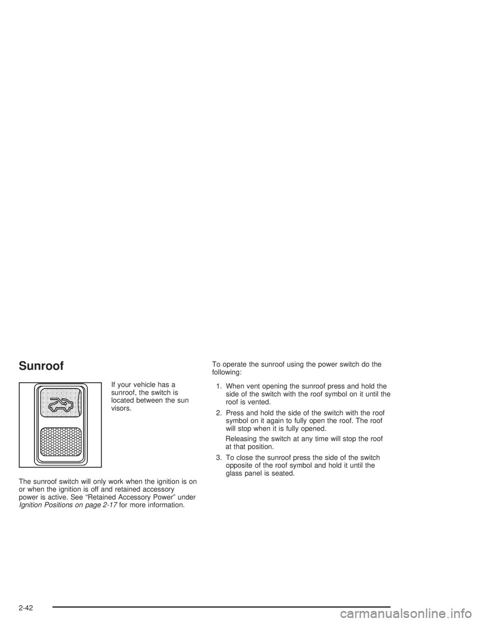
Sunroof
If your vehicle has a
sunroof, the switch is
located between the sun
visors.
The sunroof switch will only work when the ignition is on
or when the ignition is off and retained accessory
power is active. See “Retained Accessory Power” under
Ignition Positions on page 2-17for more information.To operate the sunroof using the power switch do the
following:
1. When vent opening the sunroof press and hold the
side of the switch with the roof symbol on it until the
roof is vented.
2. Press and hold the side of the switch with the roof
symbol on it again to fully open the roof. The roof
will stop when it is fully opened.
Releasing the switch at any time will stop the roof
at that position.
3. To close the sunroof press the side of the switch
opposite of the roof symbol and hold it until the
glass panel is seated.
2-42
Page 103 of 412
Manually Closing the Sunroof
If you are unable to operate the sunroof using the
switch, check the fusible link under the dashboard.
Your vehicle, when new, came with a tool for manually
operating the sunroof. See your dealer if you cannot
locate this tool in your vehicle.
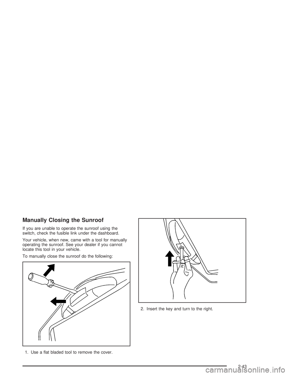
To manually close the sunroof do the following:
1. Use a flat bladed tool to remove the cover.2. Insert the key and turn to the right.
2-43
Page 104 of 412

✍NOTES
2-44
Page 105 of 412
Instrument Panel Overview...............................3-2
Hazard Warning Flashers................................3-4
Other Warning Devices...................................3-5
Horn.............................................................3-5
Tilt Wheel.....................................................3-5
Turn Signal/Multifunction Lever.........................3-6
Exterior Lamps.............................................3-11
Interior Lamps..............................................3-15
Accessory Power Outlets...............................3-16
Ashtrays and Cigarette Lighter........................3-17
Climate Controls............................................3-18
Climate Control System.................................3-18
Outlet Adjustment.........................................3-20
Warning Lights, Gages and Indicators.............3-21
Instrument Panel Cluster................................3-22
Speedometer and Odometer...........................3-24
Trip Odometer..............................................3-24
Tachometer.................................................3-24
Safety Belt Reminder Light.............................3-24
Air Bag Readiness Light................................3-25
Charging System Light..................................3-26
Voltmeter Gage............................................3-26
Brake System Warning Light..........................3-27
Anti-Lock Brake System Warning Light.............3-28
Engine Coolant Temperature Gage..................3-28Malfunction Indicator Lamp.............................3-29
Oil Pressure Gage........................................3-32
Security Light...............................................3-33
Service Four-Wheel Drive Warning Light..........3-33
Check Gages Warning Light...........................3-34
Fuel Gage...................................................3-34
Low Fuel Warning Light.................................3-35
Audio System(s).............................................3-35
Setting the Time for Radios without Radio
Data Systems (RDS)..................................3-35
Setting the Time for Radios with Radio
Data Systems (RDS)..................................3-36
AM-FM Radio...............................................3-36
Radio with CD..............................................3-39
Radio with Cassette and CD..........................3-49
Radio with Six-Disc CD.................................3-59
Theft-Deterrent Feature (Non-RDS Radios).......3-73
Theft-Deterrent Feature (RDS Radios).............3-73
Understanding Radio Reception......................3-74
Care of Your Cassette Tape Player.................3-74
Care of Your CDs.........................................3-75
Care of Your CD Player................................3-76
Fixed Mast Antenna......................................3-76
XM™ Satellite Radio Antenna System
(48 Contiguous US States).........................3-76
Section 3 Instrument Panel
3-1
Page 106 of 412

Instrument Panel Overview
3-2
Page 107 of 412
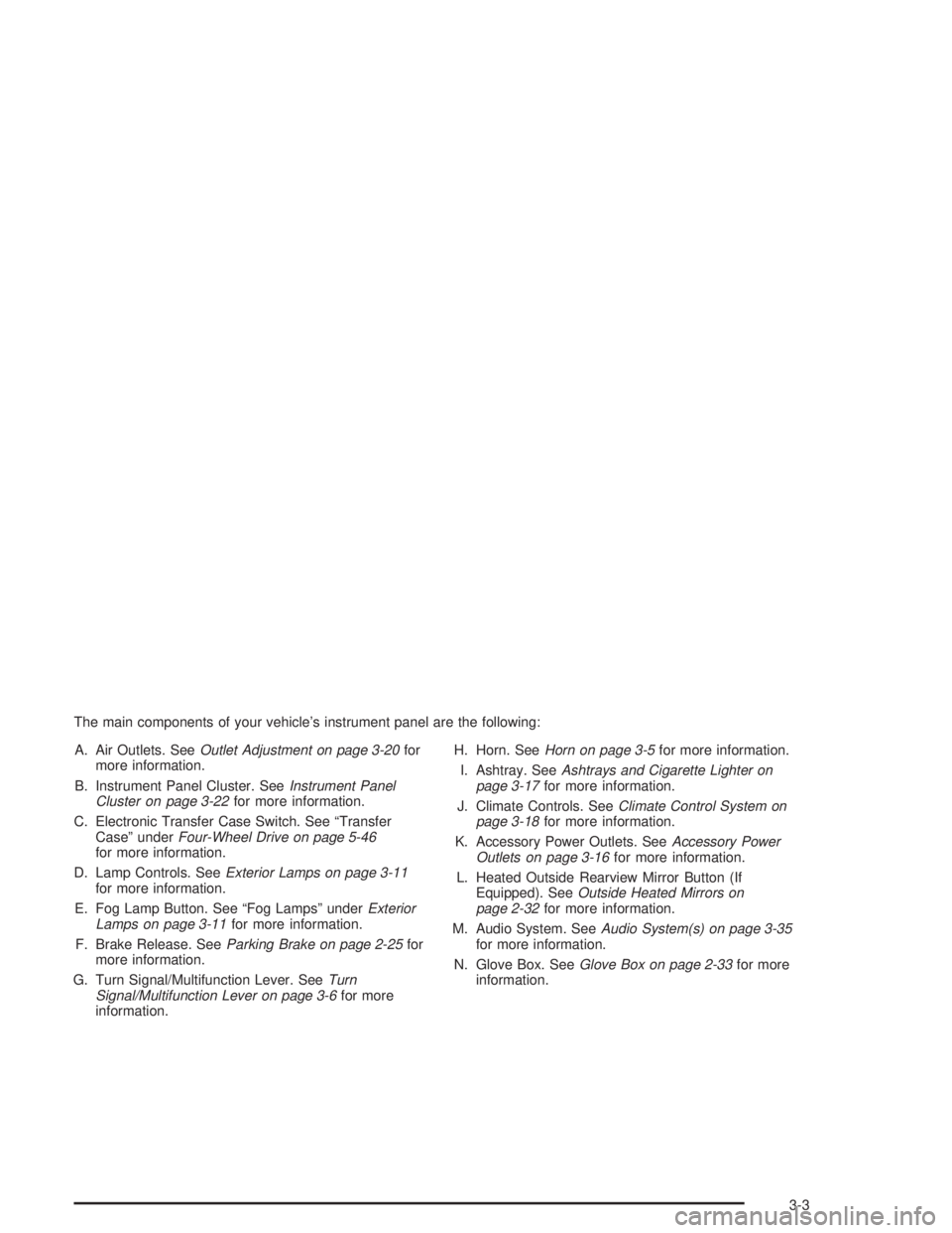
The main components of your vehicle’s instrument panel are the following:
A. Air Outlets. SeeOutlet Adjustment on page 3-20for
more information.
B. Instrument Panel Cluster. SeeInstrument Panel
Cluster on page 3-22for more information.
C. Electronic Transfer Case Switch. See “Transfer
Case” underFour-Wheel Drive on page 5-46
for more information.
D. Lamp Controls. SeeExterior Lamps on page 3-11
for more information.
E. Fog Lamp Button. See “Fog Lamps” underExterior
Lamps on page 3-11for more information.
F. Brake Release. SeeParking Brake on page 2-25for
more information.
G. Turn Signal/Multifunction Lever. SeeTurn
Signal/Multifunction Lever on page 3-6for more
information.H. Horn. SeeHorn on page 3-5for more information.
I. Ashtray. SeeAshtrays and Cigarette Lighter on
page 3-17for more information.
J. Climate Controls. SeeClimate Control System on
page 3-18for more information.
K. Accessory Power Outlets. SeeAccessory Power
Outlets on page 3-16for more information.
L. Heated Outside Rearview Mirror Button (If
Equipped). SeeOutside Heated Mirrors on
page 2-32for more information.
M. Audio System. SeeAudio System(s) on page 3-35
for more information.
N. Glove Box. SeeGlove Box on page 2-33for more
information.
3-3
Page 108 of 412
Hazard Warning Flashers
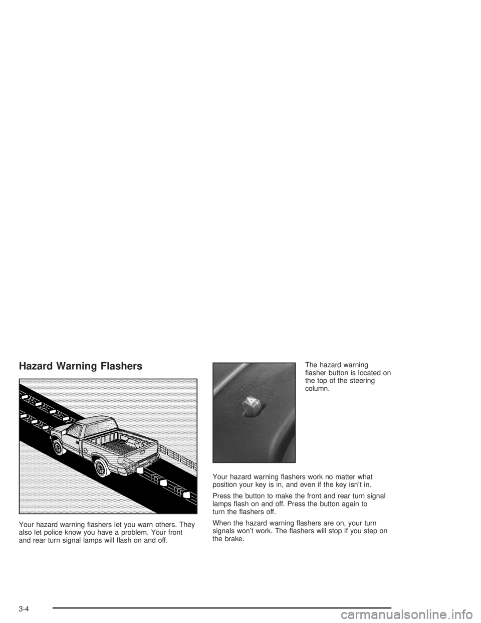
Your hazard warning flashers let you warn others. They
also let police know you have a problem. Your front
and rear turn signal lamps will flash on and off.The hazard warning
flasher button is located on
the top of the steering
column.
Your hazard warning flashers work no matter what
position your key is in, and even if the key isn’t in.
Press the button to make the front and rear turn signal
lamps flash on and off. Press the button again to
turn the flashers off.
When the hazard warning flashers are on, your turn
signals won’t work. The flashers will stop if you step on
the brake.
3-4
Page 109 of 412
Other Warning Devices
If you carry reflective triangles, you can set one up at
the side of the road about 300 feet (100 m) behind your
vehicle.
Horn
To sound the horn, press the horn symbol on the
steering wheel pad.
Tilt Wheel
A tilt wheel allows you to adjust the steering wheel
before you drive. If you have the tilt steering wheel, you
can raise it to the highest level to allow more room
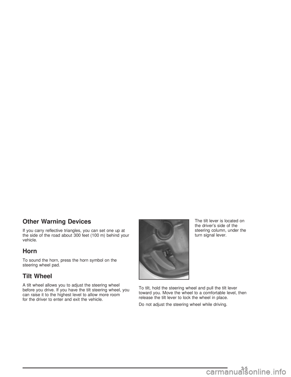
for the driver to enter and exit the vehicle.The tilt lever is located on
the driver’s side of the
steering column, under the
turn signal lever.
To tilt, hold the steering wheel and pull the tilt lever
toward you. Move the wheel to a comfortable level, then
release the tilt lever to lock the wheel in place.
Do not adjust the steering wheel while driving.
3-5
Page 110 of 412
Turn Signal/Multifunction Lever
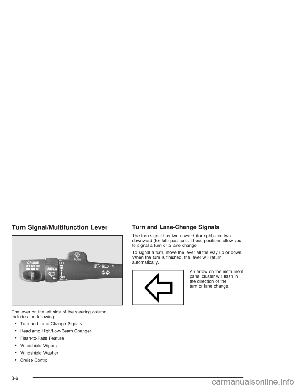
The lever on the left side of the steering column
includes the following:
•Turn and Lane Change Signals
•Headlamp High/Low-Beam Changer
•Flash-to-Pass Feature
•Windshield Wipers
•Windshield Washer
•Cruise Control
Turn and Lane-Change Signals
The turn signal has two upward (for right) and two
downward (for left) positions. These positions allow you
to signal a turn or a lane change.
To signal a turn, move the lever all the way up or down.
When the turn is finished, the lever will return
automatically.
An arrow on the instrument
panel cluster will flash in
the direction of the
turn or lane change.
3-6