clock GMC TERRAIN 2010 User Guide
[x] Cancel search | Manufacturer: GMC, Model Year: 2010, Model line: TERRAIN, Model: GMC TERRAIN 2010Pages: 410, PDF Size: 2.55 MB
Page 307 of 410

Vehicle Care 9-33
Headlamps, Front Turn
Signal, Sidemarker, and
Parking Lamps
A. Low-Beam Headlamp
B. High-Beam headlamp
C. Side Marker Lamp
D. Park/Turn Signal LampTo replace:
1. Turn the tire to reach the access
port cap located in the front of
wheel well cover.A. Screw
B. Access Port Cap
2. Remove screw (A) and turn the access port cap (B)
counterclockwise to remove.
3. If replacing a low/high headlamp bulb, remove the dust cover cap
from the back of the headlamp
housing by turning the cap
counterclockwise. 4. Turn the low/high beam or
park/turn signal bulb socket
counterclockwise to remove from
the lamp assembly.
5. Turn the sidemarker bulb socket clockwise to remove from the
lamp assembly.
6. Remove the bulb from the socket or disconnect bulb
assembly from harness
connector.
7. Install new bulb.
8. Reinstall the low/high beam or park/turn signal bulb socket to
the lamp assembly, turning
clockwise.
9. Reinstall the sidemarker bulb socket to the lamp assembly,
turning clockwise.
10. Replace the dust cover cap on headlamps.
11. Reinstall the wheel well cover access port cap and secure by
installing screw.
Page 308 of 410
9-34 Vehicle Care
Fog Lamps
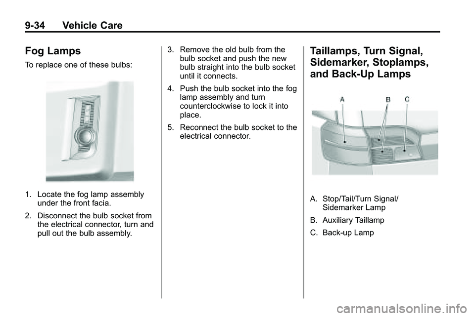
To replace one of these bulbs:
1. Locate the fog lamp assemblyunder the front facia.
2. Disconnect the bulb socket from the electrical connector, turn and
pull out the bulb assembly. 3. Remove the old bulb from the
bulb socket and push the new
bulb straight into the bulb socket
until it connects.
4. Push the bulb socket into the fog lamp assembly and turn
counterclockwise to lock it into
place.
5. Reconnect the bulb socket to the electrical connector.
Taillamps, Turn Signal,
Sidemarker, Stoplamps,
and Back-Up Lamps
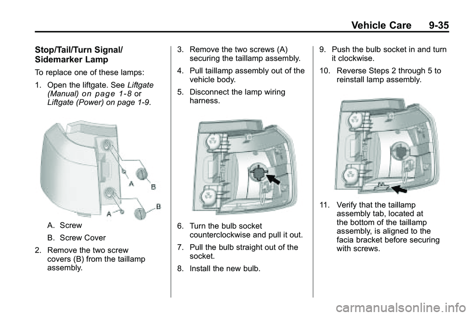
A. Stop/Tail/Turn Signal/Sidemarker Lamp
B. Auxiliary Taillamp
C. Back-up Lamp
Page 309 of 410
Vehicle Care 9-35
Stop/Tail/Turn Signal/
Sidemarker Lamp
To replace one of these lamps:
1. Open the liftgate. SeeLiftgate
(Manual)
on page 1‑8or
Liftgate (Power) on page 1‑9.
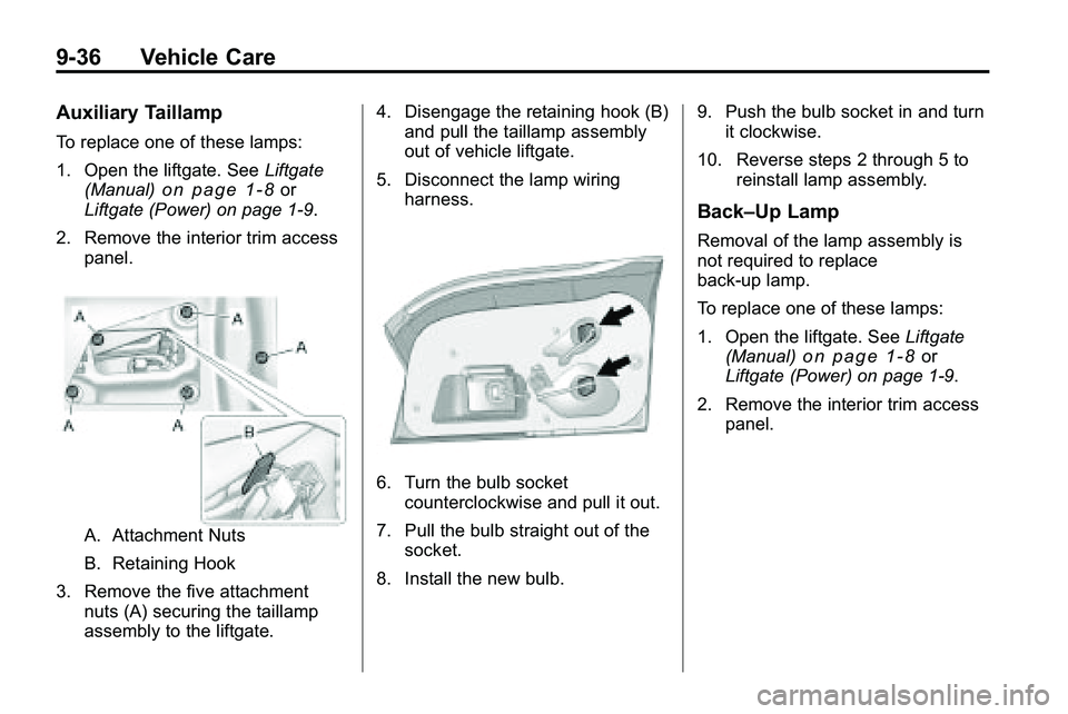
A. Screw
B. Screw Cover
2. Remove the two screw covers (B) from the taillamp
assembly. 3. Remove the two screws (A)
securing the taillamp assembly.
4. Pull taillamp assembly out of the vehicle body.
5. Disconnect the lamp wiring harness.6. Turn the bulb socketcounterclockwise and pull it out.
7. Pull the bulb straight out of the socket.
8. Install the new bulb. 9. Push the bulb socket in and turn
it clockwise.
10. Reverse Steps 2 through 5 to reinstall lamp assembly.
11. Verify that the taillampassembly tab, located at
the bottom of the taillamp
assembly, is aligned to the
facia bracket before securing
with screws.
Page 310 of 410
9-36 Vehicle Care
Auxiliary Taillamp
To replace one of these lamps:
1. Open the liftgate. SeeLiftgate
(Manual)
on page 1‑8or
Liftgate (Power) on page 1‑9.
2. Remove the interior trim access panel.
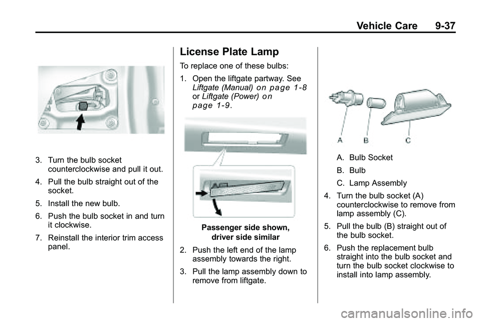
A. Attachment Nuts
B. Retaining Hook
3. Remove the five attachment nuts (A) securing the taillamp
assembly to the liftgate. 4. Disengage the retaining hook (B)
and pull the taillamp assembly
out of vehicle liftgate.
5. Disconnect the lamp wiring harness.
6. Turn the bulb socketcounterclockwise and pull it out.
7. Pull the bulb straight out of the socket.
8. Install the new bulb. 9. Push the bulb socket in and turn
it clockwise.
10. Reverse steps 2 through 5 to reinstall lamp assembly.
Back–Up Lamp
Removal of the lamp assembly is
not required to replace
back-up lamp.
To replace one of these lamps:
1. Open the liftgate. See Liftgate
(Manual)
on page 1‑8or
Liftgate (Power) on page 1‑9.
2. Remove the interior trim access panel.
Page 311 of 410
Vehicle Care 9-37
3. Turn the bulb socketcounterclockwise and pull it out.
4. Pull the bulb straight out of the socket.
5. Install the new bulb.
6. Push the bulb socket in and turn it clockwise.
7. Reinstall the interior trim access panel.
License Plate Lamp
To replace one of these bulbs:
1. Open the liftgate partway. SeeLiftgate (Manual)
on page 1‑8orLiftgate (Power)on
page 1‑9.
Passenger side shown,
driver side similar
2. Push the left end of the lamp assembly towards the right.
3. Pull the lamp assembly down to remove from liftgate.
A. Bulb Socket
B. Bulb
C. Lamp Assembly
4. Turn the bulb socket (A) counterclockwise to remove from
lamp assembly (C).
5. Pull the bulb (B) straight out of the bulb socket.
6. Push the replacement bulb straight into the bulb socket and
turn the bulb socket clockwise to
install into lamp assembly.
Page 343 of 410
Vehicle Care 9-69
Tire Changing
Removing the Spare Tire and
Tools
To access the spare tire and tools:
1. Open the liftgate. SeeLiftgate
(Manual)
on page 1‑8or
Liftgate (Power) on page 1‑9.
2. Lift the load floor up.
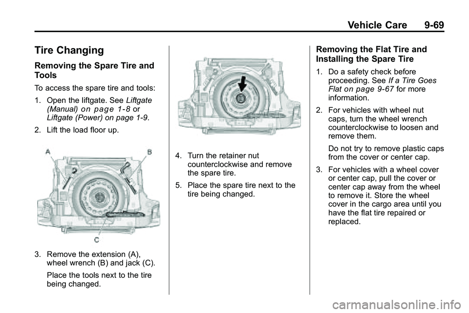
3. Remove the extension (A), wheel wrench (B) and jack (C).
Place the tools next to the tire
being changed.
4. Turn the retainer nutcounterclockwise and remove
the spare tire.
5. Place the spare tire next to the tire being changed.
Removing the Flat Tire and
Installing the Spare Tire
1. Do a safety check beforeproceeding. See If a Tire Goes
Flat
on page 9‑67for more
information.
2. For vehicles with wheel nut caps, turn the wheel wrench
counterclockwise to loosen and
remove them.
Do not try to remove plastic caps
from the cover or center cap.
3. For vehicles with a wheel cover or center cap, pull the cover or
center cap away from the wheel
to remove it. Store the wheel
cover in the cargo area until you
have the flat tire repaired or
replaced.
Page 344 of 410
9-70 Vehicle Care
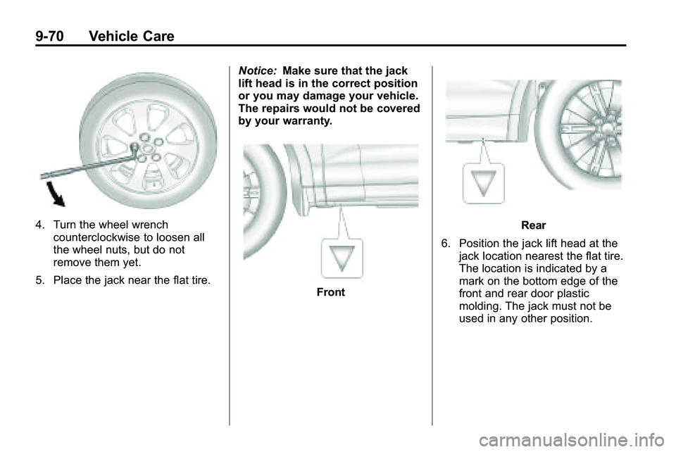
4. Turn the wheel wrenchcounterclockwise to loosen all
the wheel nuts, but do not
remove them yet.
5. Place the jack near the flat tire. Notice:
Make sure that the jack
lift head is in the correct position
or you may damage your vehicle.
The repairs would not be covered
by your warranty.
Front
Rear
6. Position the jack lift head at the jack location nearest the flat tire.
The location is indicated by a
mark on the bottom edge of the
front and rear door plastic
molding. The jack must not be
used in any other position.
Page 346 of 410
9-72 Vehicle Care
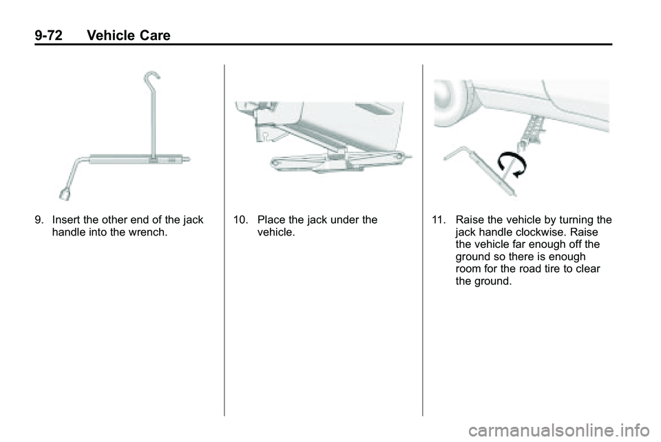
9. Insert the other end of the jackhandle into the wrench.10. Place the jack under the vehicle.11. Raise the vehicle by turning thejack handle clockwise. Raise
the vehicle far enough off the
ground so there is enough
room for the road tire to clear
the ground.
Page 348 of 410
9-74 Vehicle Care
16. Reinstall the wheel nuts.Tighten each nut by hand until
the wheel is held against
the hub.
17. Lower the vehicle by turning the jack handle
counterclockwise.
{WARNING
Wheel nuts that are improperly or
incorrectly tightened can cause
the wheels to become loose or
come off. The wheel nuts should
be tightened with a torque wrench
to the proper torque specification
after replacing. Follow the torque
specification supplied by the
aftermarket manufacturer when
using accessory locking wheel
nuts. See Capacities and
Specifications
on page 11‑2for
original equipment wheel nut
torque specifications. Notice:
Improperly tightened
wheel nuts can lead to brake
pulsation and rotor damage. To
avoid expensive brake repairs,
evenly tighten the wheel nuts in
the proper sequence and to the
proper torque specification. See
Capacities and Specifications
on
page 11‑2for the wheel nut
torque specification.
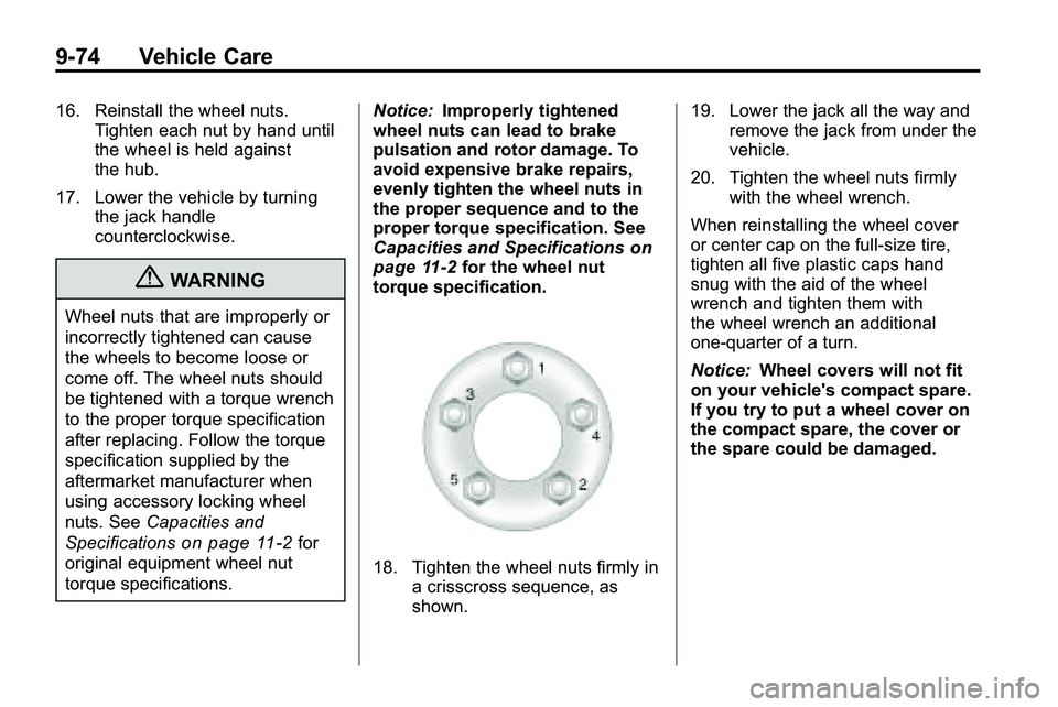
18. Tighten the wheel nuts firmly in a crisscross sequence, as
shown. 19. Lower the jack all the way and
remove the jack from under the
vehicle.
20. Tighten the wheel nuts firmly with the wheel wrench.
When reinstalling the wheel cover
or center cap on the full-size tire,
tighten all five plastic caps hand
snug with the aid of the wheel
wrench and tighten them with
the wheel wrench an additional
one‐quarter of a turn.
Notice: Wheel covers will not fit
on your vehicle's compact spare.
If you try to put a wheel cover on
the compact spare, the cover or
the spare could be damaged.
Page 401 of 410
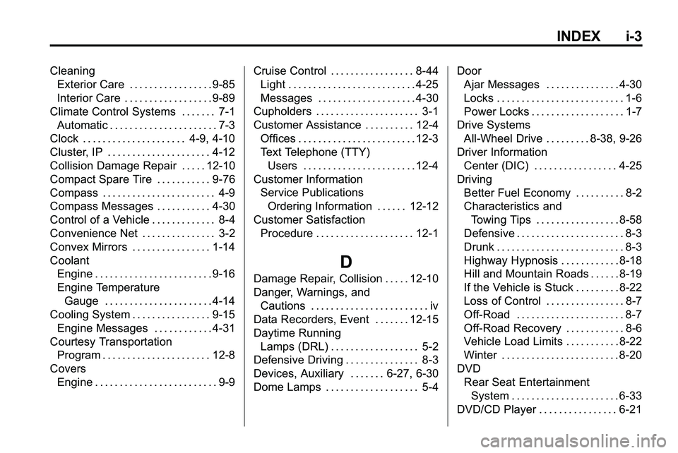
INDEX i-3
CleaningExterior Care . . . . . . . . . . . . . . . . . 9-85
Interior Care . . . . . . . . . . . . . . . . . . 9-89
Climate Control Systems . . . . . . . 7-1 Automatic . . . . . . . . . . . . . . . . . . . . . . 7-3
Clock . . . . . . . . . . . . . . . . . . . . . 4-9, 4-10
Cluster, IP . . . . . . . . . . . . . . . . . . . . . 4-12
Collision Damage Repair . . . . . 12-10
Compact Spare Tire . . . . . . . . . . . 9-76
Compass . . . . . . . . . . . . . . . . . . . . . . . 4-9
Compass Messages . . . . . . . . . . . 4-30
Control of a Vehicle . . . . . . . . . . . . . 8-4
Convenience Net . . . . . . . . . . . . . . . 3-2
Convex Mirrors . . . . . . . . . . . . . . . . 1-14
Coolant Engine . . . . . . . . . . . . . . . . . . . . . . . . 9-16
Engine Temperature
Gauge . . . . . . . . . . . . . . . . . . . . . . 4-14
Cooling System . . . . . . . . . . . . . . . . 9-15 Engine Messages . . . . . . . . . . . . 4-31
Courtesy Transportation
Program . . . . . . . . . . . . . . . . . . . . . . 12-8
Covers Engine . . . . . . . . . . . . . . . . . . . . . . . . . 9-9 Cruise Control . . . . . . . . . . . . . . . . . 8-44
Light . . . . . . . . . . . . . . . . . . . . . . . . . . 4-25
Messages . . . . . . . . . . . . . . . . . . . . 4-30
Cupholders . . . . . . . . . . . . . . . . . . . . . 3-1
Customer Assistance . . . . . . . . . . 12-4 Offices . . . . . . . . . . . . . . . . . . . . . . . . 12-3
Text Telephone (TTY)Users . . . . . . . . . . . . . . . . . . . . . . . 12-4
Customer Information Service PublicationsOrdering Information . . . . . . 12-12
Customer Satisfaction Procedure . . . . . . . . . . . . . . . . . . . . 12-1
D
Damage Repair, Collision . . . . . 12-10
Danger, Warnings, andCautions . . . . . . . . . . . . . . . . . . . . . . . . iv
Data Recorders, Event . . . . . . . 12-15
Daytime Running Lamps (DRL) . . . . . . . . . . . . . . . . . . 5-2
Defensive Driving . . . . . . . . . . . . . . . 8-3
Devices, Auxiliary . . . . . . . 6-27, 6-30
Dome Lamps . . . . . . . . . . . . . . . . . . . 5-4 Door
Ajar Messages . . . . . . . . . . . . . . . 4-30
Locks . . . . . . . . . . . . . . . . . . . . . . . . . . 1-6
Power Locks . . . . . . . . . . . . . . . . . . . 1-7
Drive Systems All-Wheel Drive . . . . . . . . . 8-38, 9-26
Driver Information
Center (DIC) . . . . . . . . . . . . . . . . . 4-25
Driving Better Fuel Economy . . . . . . . . . . 8-2
Characteristics andTowing Tips . . . . . . . . . . . . . . . . . 8-58
Defensive . . . . . . . . . . . . . . . . . . . . . . 8-3
Drunk . . . . . . . . . . . . . . . . . . . . . . . . . . 8-3
Highway Hypnosis . . . . . . . . . . . . 8-18
Hill and Mountain Roads . . . . . . 8-19
If the Vehicle is Stuck . . . . . . . . . 8-22
Loss of Control . . . . . . . . . . . . . . . . 8-7
Off-Road . . . . . . . . . . . . . . . . . . . . . . 8-7
Off-Road Recovery . . . . . . . . . . . . 8-6
Vehicle Load Limits . . . . . . . . . . . 8-22
Winter . . . . . . . . . . . . . . . . . . . . . . . . 8-20
DVD Rear Seat EntertainmentSystem . . . . . . . . . . . . . . . . . . . . . . 6-33
DVD/CD Player . . . . . . . . . . . . . . . . 6-21