turn signal GMC YUKON HYBRID 2009 Owners Manual
[x] Cancel search | Manufacturer: GMC, Model Year: 2009, Model line: YUKON HYBRID, Model: GMC YUKON HYBRID 2009Pages: 94, PDF Size: 0.53 MB
Page 37 of 94
Service............................................................5-2
Doing Your Own Service Work.........................5-2
Checking Things Under the Hood.....................5-3
High Voltage Devices and Wiring......................5-3
Engine Compartment Overview.........................5-4
Automatic Transmission Fluid...........................5-5
Drive Motor/Generator Control Module (DMCM)
Coolant Surge Tank Pressure Cap..................5-6
Drive Motor/Generator Control Module (DMCM)
Cooling System...........................................5-6
Power Steering Fluid.....................................5-11
Brakes........................................................5-11
Battery........................................................5-15
Jump Starting...............................................5-16
Bulb Replacement..........................................5-21
Taillamps, Turn Signal, Stoplamps and
Back-up Lamps.........................................5-21
Replacement Bulbs.......................................5-22Electrical System............................................5-22
Fuses and Circuit Breakers............................5-22
Underhood Fuse Block..................................5-22
Tires..............................................................5-24
Inflation - Tire Pressure.................................5-24
Tire Pressure Monitor Operation.....................5-25
Tire Inspection and Rotation...........................5-29
Tire Chains..................................................5-30
If a Tire Goes Flat........................................5-30
Tire Sealant and Compressor Kit
(Without Selector Switch)............................5-32
Tire Sealant and Compressor Kit
(With Selector Switch)................................5-42
Tire Sealant and Compressor Kit Storage.........5-50
Capacities and Speci�cations..........................5-52
Section 5 Service and Appearance Care
5-1
Page 57 of 94
Bulb Replacement
Taillamps, Turn Signal, Stoplamps
and Back-up Lamps
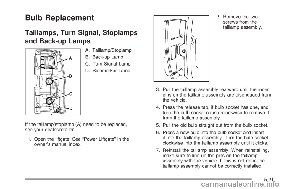
A. Taillamp/Stoplamp
B. Back-up Lamp
C. Turn Signal Lamp
D. Sidemarker Lamp
If the taillamp/stoplamp (A) need to be replaced,
see your dealer/retailer.
1. Open the liftgate. See “Power Liftgate” in the
owner’s manual index.2. Remove the two
screws from the
taillamp assembly.
3. Pull the taillamp assembly rearward until the inner
pins on the taillamp assembly are disengaged from
the vehicle.
4. Press the release tab, if bulb socket has one, and
turn the bulb socket counterclockwise to remove it
from the taillamp assembly.
5. Pull the old bulb straight out from the bulb socket.
6. Press a new bulb into the bulb socket and insert
it into the taillamp assembly. Turn the bulb socket
clockwise into the taillamp assembly until it clicks.
7. Reinstall the taillamp assembly. When reinstalling,
make sure to line up the pins on the taillamp
assembly with the vehicle. If this is not done the
taillamp assembly cannot be correctly installed.
5-21
Page 58 of 94
Replacement Bulbs
Exterior Lamp Bulb Number
Back-up Lamp and Rear Turn
Signal Lamp3156
Sidemarker Lamp 194
For replacement bulbs not listed here, contact your
dealer/retailer.
Electrical System
Fuses and Circuit Breakers
The wiring circuits in the vehicle are protected from
short circuits by a combination of fuses, circuit breakers
and fusible thermal links. This greatly reduces the
chance of fires caused by electrical problems.
Be sure you replace a bad fuse with a new one of the
identical size and rating.If you ever have a problem on the road and do not have
a spare fuse, you can borrow one that has the same
amperage. Just pick some feature of the vehicle that you
can get along without, like the radio or cigarette
lighter, and use its fuse, if it is the correct amperage.
Replace it as soon as you can.
The vehicle also has a special fuse in the battery box
for the 300-volt batteries. If this fuse has failed and
needs to be replaced, the vehicle will be disabled and
you will need to have the vehicle repaired by your
dealer/retailer. Do not attempt to self-service this fuse.
Underhood Fuse Block
Hybrid Auxiliary Underhood Fuse
Block
The hybrid underhood fuse block is located in the
engine compartment near the front of the vehicle.
Lift the cover for access to the fuse/relay block.
SeeEngine Compartment Overview on page 5-4for
more information on its location. For more information on
the main underhood fuse block, see “Underhood Fuse
Block” in the owner manual.
5-22
Page 64 of 94
You have two minutes to match the first tire/wheel
position, and five minutes overall to match all four
tire/wheel positions. If it takes longer than two minutes,
to match the first tire and wheel, or more than
five minutes to match all four tire and wheel positions
the matching process stops and you need to start over.
The TPMS sensor matching process is outlined below:
1. Set the parking brake.
2. Turn the ignition switch to ON/RUN with the
engine off.
3. Press the Remote Keyless Entry (RKE) transmitter’s
LOCK and UNLOCK buttons at the same time for
approximately five seconds. The horn sounds twice
to signal the receiver is in relearn mode and TIRE
LEARNING ACTIVE message displays on the
DIC screen.
4. Start with the driver side front tire.
5. Remove the valve cap from the valve cap stem.
Activate the TPMS sensor by increasing or
decreasing the tire’s air pressure for five seconds,
or until a horn chirp sounds. The horn chirp,
which may take up to 30 seconds to sound,
confirms that the sensor identification code has
been matched to this tire and wheel position.6. Proceed to the passenger side front tire, and repeat
the procedure in Step 5.
7. Proceed to the passenger side rear tire, and repeat
the procedure in Step 5.
8. Proceed to the driver side rear tire, and repeat the
procedure in Step 5. The horn sounds two times to
indicate the sensor identification code has been
matched to the driver side rear tire, and the TPMS
sensor matching process is no longer active.
The TIRE LEARNING ACTIVE message on the
DIC display screen goes off.
9. Turn the ignition switch to LOCK/OFF.
10. Set all four tires to the recommended air pressure
level as indicated on the Tire and Loading
Information label.
11. Put the valve caps back on the valve stems.
5-28
Page 91 of 94
A
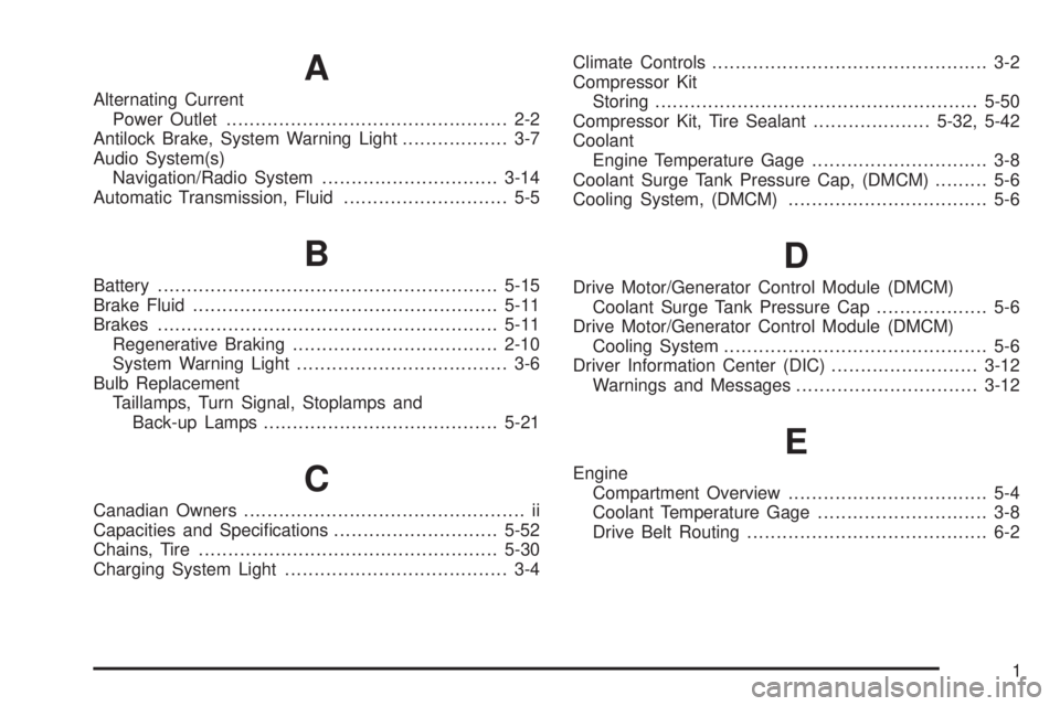
Alternating Current
Power Outlet................................................ 2-2
Antilock Brake, System Warning Light.................. 3-7
Audio System(s)
Navigation/Radio System..............................3-14
Automatic Transmission, Fluid............................ 5-5
B
Battery..........................................................5-15
Brake Fluid....................................................5-11
Brakes..........................................................5-11
Regenerative Braking...................................2-10
System Warning Light.................................... 3-6
Bulb Replacement
Taillamps, Turn Signal, Stoplamps and
Back-up Lamps........................................5-21
C
Canadian Owners................................................ ii
Capacities and Specifications............................5-52
Chains, Tire...................................................5-30
Charging System Light...................................... 3-4Climate Controls............................................... 3-2
Compressor Kit
Storing.......................................................5-50
Compressor Kit, Tire Sealant....................5-32, 5-42
Coolant
Engine Temperature Gage.............................. 3-8
Coolant Surge Tank Pressure Cap, (DMCM)......... 5-6
Cooling System, (DMCM).................................. 5-6
D
Drive Motor/Generator Control Module (DMCM)
Coolant Surge Tank Pressure Cap................... 5-6
Drive Motor/Generator Control Module (DMCM)
Cooling System............................................. 5-6
Driver Information Center (DIC).........................3-12
Warnings and Messages...............................3-12
E
Engine
Compartment Overview.................................. 5-4
Coolant Temperature Gage............................. 3-8
Drive Belt Routing......................................... 6-2
1
Page 94 of 94
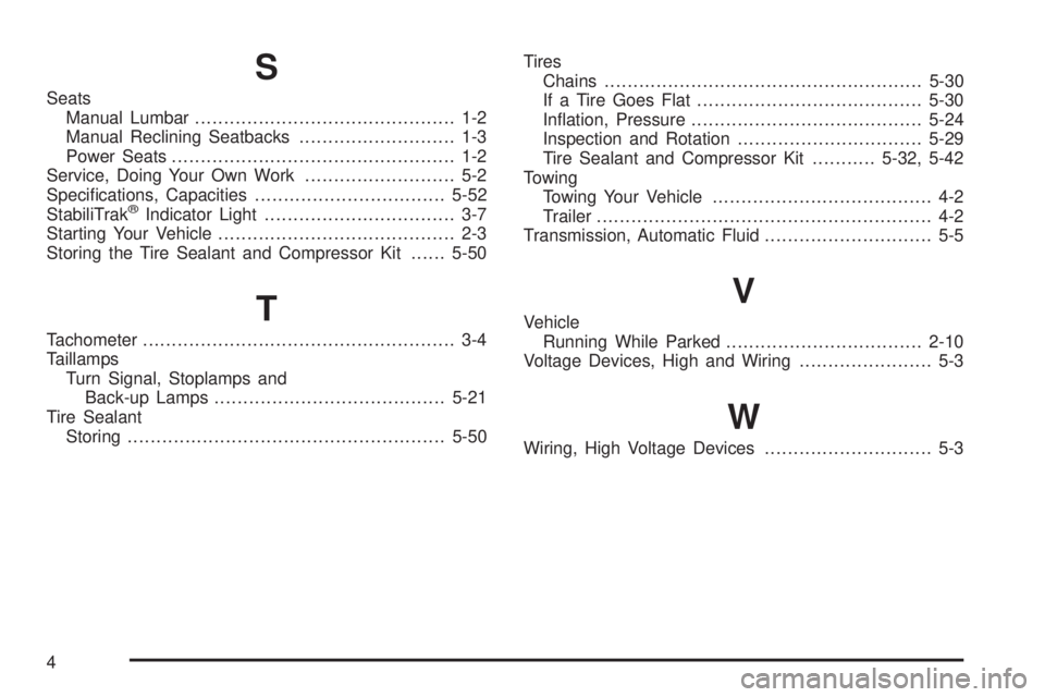
S
Seats
Manual Lumbar............................................. 1-2
Manual Reclining Seatbacks........................... 1-3
Power Seats................................................. 1-2
Service, Doing Your Own Work.......................... 5-2
Specifications, Capacities.................................5-52
StabiliTrak
®Indicator Light................................. 3-7
Starting Your Vehicle......................................... 2-3
Storing the Tire Sealant and Compressor Kit......5-50
T
Tachometer...................................................... 3-4
Taillamps
Turn Signal, Stoplamps and
Back-up Lamps........................................5-21
Tire Sealant
Storing.......................................................5-50Tires
Chains.......................................................5-30
If a Tire Goes Flat.......................................5-30
Inflation, Pressure........................................5-24
Inspection and Rotation................................5-29
Tire Sealant and Compressor Kit...........5-32, 5-42
Towing
Towing Your Vehicle...................................... 4-2
Trailer.......................................................... 4-2
Transmission, Automatic Fluid............................. 5-5
V
Vehicle
Running While Parked..................................2-10
Voltage Devices, High and Wiring....................... 5-3
W
Wiring, High Voltage Devices............................. 5-3
4