stop start GMC YUKON HYBRID 2010 User Guide
[x] Cancel search | Manufacturer: GMC, Model Year: 2010, Model line: YUKON HYBRID, Model: GMC YUKON HYBRID 2010Pages: 120, PDF Size: 1.03 MB
Page 36 of 120
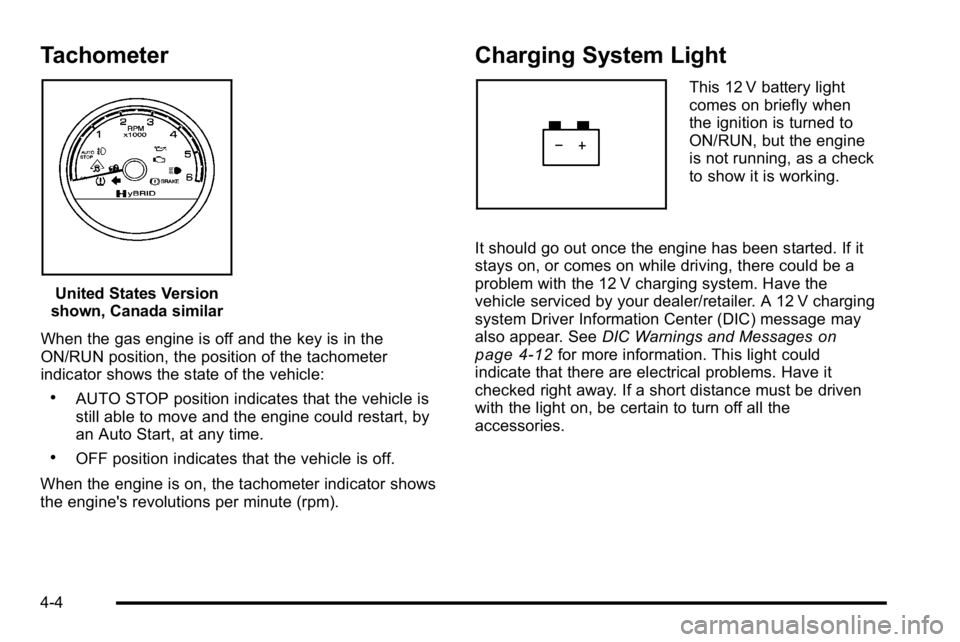
Tachometer
United States Version
shown, Canada similar
When the gas engine is off and the key is in the
ON/RUN position, the position of the tachometer
indicator shows the state of the vehicle:
.AUTO STOP position indicates that the vehicle is
still able to move and the engine could restart, by
an Auto Start, at any time.
.OFF position indicates that the vehicle is off.
When the engine is on, the tachometer indicator shows
the engine's revolutions per minute (rpm).
Charging System Light
This 12 V battery light
comes on briefly when
the ignition is turned to
ON/RUN, but the engine
is not running, as a check
to show it is working.
It should go out once the engine has been started. If it
stays on, or comes on while driving, there could be a
problem with the 12 V charging system. Have the
vehicle serviced by your dealer/retailer. A 12 V charging
system Driver Information Center (DIC) message may
also appear. See DIC Warnings and Messages
on
page 4‑12for more information. This light could
indicate that there are electrical problems. Have it
checked right away. If a short distance must be driven
with the light on, be certain to turn off all the
accessories.
4-4
Page 39 of 120
Antilock Brake System (ABS)
Warning Light
For vehicles with the
Antilock Brake System
(ABS), this light comes on
briefly when the engine is
in ON/RUN.
That is normal. If the light does not come on then, have
it fixed so it will be ready to warn if there is a problem.
If the ABS light stays on, turn the ignition off, if the light
comes on while driving, stop as soon as it is safely
possible and turn the ignition off. Then start the engine
again to reset the system. If the ABS light still stays on,
or comes on again while driving, the vehicle needs
service. If the regular brake system warning light is not
on, the vehicle still has brakes, but not antilock brakes.
If the regular brake system warning light is also on, the
vehicle does not have antilock brakes and there is a
problem with the regular brakes. See Brake System
Warning Light on page 4‑6.
For vehicles with a Driver Information Center (DIC),
see DIC Warnings and Messages
on page 4‑12for all
brake related DIC messages.
StabiliTrak®Indicator Light
For vehicles with
StabiliTrak, this warning
light comes on briefly
when the ignition is in
ON/RUN.
If it does not, have the vehicle serviced by your
dealer/retailer. If the system is working normally the
indicator light goes off.
If the light comes on and stays on while driving, there
could be a problem with the StabiliTrak system and the
vehicle might need service. When this warning light is
on, the StabiliTrak system is off and does not limit
wheel spin.
The light flashes if the system is active and is working
to assist the driver with directional control of the vehicle
in difficult driving conditions.
See the owner manual for more information.
4-7
Page 41 of 120
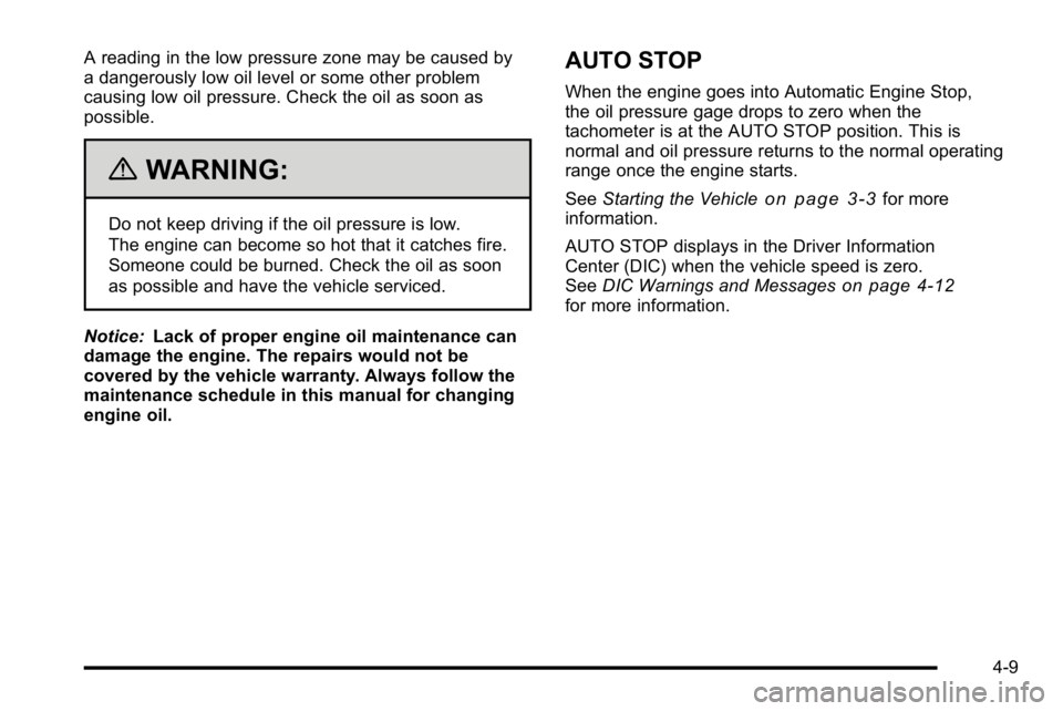
A reading in the low pressure zone may be caused by
a dangerously low oil level or some other problem
causing low oil pressure. Check the oil as soon as
possible.
{WARNING:
Do not keep driving if the oil pressure is low.
The engine can become so hot that it catches fire.
Someone could be burned. Check the oil as soon
as possible and have the vehicle serviced.
Notice: Lack of proper engine oil maintenance can
damage the engine. The repairs would not be
covered by the vehicle warranty. Always follow the
maintenance schedule in this manual for changing
engine oil.
AUTO STOP
When the engine goes into Automatic Engine Stop,
the oil pressure gage drops to zero when the
tachometer is at the AUTO STOP position. This is
normal and oil pressure returns to the normal operating
range once the engine starts.
See Starting the Vehicle
on page 3‑3for more
information.
AUTO STOP displays in the Driver Information
Center (DIC) when the vehicle speed is zero.
See DIC Warnings and Messages
on page 4‑12for more information.
4-9
Page 44 of 120
Driver Information Center (DIC)
Trip/Fuel Menu Items
Press the trip/fuel button to display the Trip/Fuel Menu
items. For more items see“DIC Operation and
Displays” in the owner manual.
BATTERY VOLTAGE
This display shows the current battery voltage. If the
voltage is in the normal range, the value will display.
For example, the display may read BATTERY
VOLTAGE 13.2 VOLTS. If the voltage is high or low,
the display will read HIGH or LOW. Your vehicle's
charging system regulates voltage based on the state
of the battery. The battery voltage may fluctuate when
viewing this information on the DIC. This is normal.
See“Charging System Light” in the owner manual for
more information. If there is a problem with the battery
charging system, the DIC will display a message.
See DIC Warnings and Messages on page 4‑12.
INST ECON (Instantaneous Economy)
This display normally shows instantaneous fuel
economy. When the vehicle is in Auto Stop mode
AUTO STOP or INST ECON = 99 MPG (l/00km) will be
displayed. See Starting the Vehicle
on page 3‑3for
more information.
DIC Warnings and Messages
Warning messages are displayed on the DIC to notify
the driver that the status of the vehicle has changed
and that some action may be needed by the driver to
correct the condition. If there is more than one message
that needs to be displayed they will appear one after
another.
Some messages may not require immediate action, but
you can press any of the DIC buttons on the instrument
panel or the trip odometer reset stem to acknowledge
that you received the messages and to clear them from
the display.
Some messages cannot be cleared from the DIC
display because they are more urgent. These
messages require action before they can be cleared.
You should take any messages that appear on the
display seriously and remember that clearing the
messages will only make the messages disappear, not
correct the problem.
For information on other DIC messages, see “DIC
Warnings and Messages” in the owner manual Index.
HOOD OPEN
If the hood is not fully closed or there is a problem with
the hood switch, this message will be displayed. Close
the hood to clear the message. If the HOOD OPEN
message continues to be displayed after verifying the
4-12
Page 45 of 120
hood is closed, you should have the hood switch
serviced. Failure to service the hood switch properly
can result in an Auto Start condition.
Auto Stops will be disabled when this message is
displayed. If the vehicle is in auto stop mode when this
message appears, the engine will instantly start.
OIL PRESSURE LOW STOP ENGINE
If engine oil pressure is low, this message will be
displayed on the DIC. Stop the vehicle as soon as
safely possible and do not operate it until the cause of
the low oil pressure has been corrected. Check your oil
level as soon as possible and have your vehicle
serviced. See“Engine Oil”in the owner manual Index.
SERVICE 4 WHEEL DRIVE
This message may display if a problem occurs with the
four-wheel-drive system. If this message appears, stop
as soon as possible and turn off the vehicle. Make sure
the key is in the LOCK/OFF position for at least
one minute and then restart the vehicle and check for
the message on the DIC display. If the message is still
displayed or appears again when you begin driving,
the four-wheel-drive system needs service. See your
dealer/retailer.
SERVICE BATTERY CHARGING
SYSTEM
If the 12V battery system faults or fails this message will
appear on the DIC. The battery/charging system light
will appear in the instrument panel cluster. See “Battery
Warning Light” in the owner manual Index. Driving with
this message on could drain the battery. Have the
electrical system checked as soon as possible.
SERVICE BRAKE SYSTEM
This message will be displayed if there is a problem
with the brake system. You will still be able to brake, but
it will be noticeably more difficult. Pull off the road to a
safe location and have your vehicle towed to the
nearest dealer/retailer for service. See “Brakes,”
“Brake System Warning Light,” and“ABS Brake System
Warning Light” in the owner manual Index.
SERVICE HYBRID SYSTEM
If this message is displayed on the DIC, the vehicle may
continue to operate, but you need to have it serviced as
soon as possible.
SERVICE POWER STEERING
This message displays if a problem has been detected
with the electric power steering. Have your vehicle
serviced by your dealer/retailer immediately.
4-13
Page 57 of 120
Section 6 Service and Appearance Care
Service. . . . . . . . . . . . . . . . . . . . . . . . . . . . . . . . . . . . . . . . . . . . . 6-2
Doing Your Own Service Work . . . . . . . . . . . . . . . . . . 6-2
Checking Things Under the Hood . . . . . . . . . . . . . . . . .6-3
High Voltage Devices and Wiring . . . . . . . . . . . . . . . 6-3
Engine Compartment Overview . . . . . . . . . . . . . . . . . 6-4
Automatic Transmission Fluid . . . . . . . . . . . . . . . . . . . 6-5
Drive Motor/Generator Control Module (DMCM) Coolant Surge Tank Pressure Cap . . . . . . . . . . . . 6-8
Drive Motor/Generator Control Module (DMCM) Cooling System . . . . . . . . . . . . . . . . . . . . . . . . . . . . . . . 6-9
Power Steering Fluid . . . . . . . . . . . . . . . . . . . . . . . . . . 6-13
Brakes . . . . . . . . . . . . . . . . . . . . . . . . . . . . . . . . . . . . . . . . . 6-13
Battery . . . . . . . . . . . . . . . . . . . . . . . . . . . . . . . . . . . . . . . . . 6-16
Jump Starting . . . . . . . . . . . . . . . . . . . . . . . . . . . . . . . . . . 6-18
Bulb Replacement . . . . . . . . . . . . . . . . . . . . . . . . . . . . . . . . 6-24
Taillamps, Turn Signal, Stoplamps and Back-up Lamps . . . . . . . . . . . . . . . . . . . . . . . . . . . . . . 6-24
Replacement Bulbs . . . . . . . . . . . . . . . . . . . . . . . . . . . . 6-25 Electrical System
. . . . . . . . . . . . . . . . . . . . . . . . . . . . . . . . . 6-25
High Voltage Devices and Wiring . . . . . . . . . . . . . . 6-25
Fuses and Circuit Breakers . . . . . . . . . . . . . . . . . . . . 6-26
Underhood Fuse Block . . . . . . . . . . . . . . . . . . . . . . . . 6-26
Tires . . . . . . . . . . . . . . . . . . . . . . . . . . . . . . . . . . . . . . . . . . . . . . . 6-28
Inflation - Tire Pressure . . . . . . . . . . . . . . . . . . . . . . . . 6-28
Tire Pressure Monitor Operation . . . . . . . . . . . . . . . 6-29
Tire Inspection and Rotation . . . . . . . . . . . . . . . . . . . 6-33
Tire Chains . . . . . . . . . . . . . . . . . . . . . . . . . . . . . . . . . . . . 6-34
If a Tire Goes Flat . . . . . . . . . . . . . . . . . . . . . . . . . . . . . 6-34
Tire Sealant and Compressor Kit (Without Selector Switch) . . . . . . . . . . . . . . . . . . . . 6-35
Tire Sealant and Compressor Kit (With Selector Switch) . . . . . . . . . . . . . . . . . . . . . . . 6-45
Tire Sealant and Compressor Kit Storage . . . . . . 6-55
Appearance Care . . . . . . . . . . . . . . . . . . . . . . . . . . . . . . . . . 6-56
Vehicle Care/Appearance Materials . . . . . . . . . . . . 6-56
Capacities and Specifications . . . . . . . . . . . . . . . . . . .6-57
6-1
Page 68 of 120
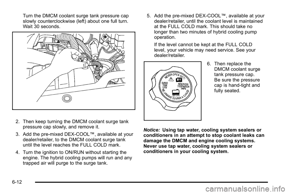
Turn the DMCM coolant surge tank pressure cap
slowly counterclockwise (left) about one full turn.
Wait 30 seconds.
2. Then keep turning the DMCM coolant surge tankpressure cap slowly, and remove it.
3. Add the pre‐mixed DEX‐COOL™, available at your dealer/retailer, to the DMCM coolant surge tank
until the level reaches the FULL COLD mark.
4. Turn the ignition to ON/RUN without starting the engine. The hybrid cooling pumps will run and any
trapped air will purge to the surge tank. 5. Add the pre‐mixed DEX‐COOL™, available at your
dealer/retailer, until the coolant level is maintained
at the FULL COLD mark. This should take no
longer than two minutes of hybrid cooling pump
operation.
If the level cannot be kept at the FULL COLD
level, your vehicle may need service. See your
dealer/retailer.
6. Then replace the
DMCM coolant surge
tank pressure cap.
Be sure the pressure
cap is hand-tight and
fully seated.
Notice: Using tap water, cooling system sealers or
conditioners in an attempt to stop coolant leaks can
damage the DMCM and engine cooling systems.
Never use tap water, cooling system sealers or
conditioners in your cooling system.
6-12
Page 88 of 120
TPMS Sensor Matching Process
Each TPMS sensor has a unique identification code.
Any time you rotate your vehicle's tires or replace one
or more of the TPMS sensors, the identification codes
will need to be matched to the new tire/wheel position.
The sensors are matched to the tire/wheel positions in
the following order: driver side front tire, passenger
side front tire, passenger side rear tire, and driver side
rear tire using a TPMS diagnostic tool. See your
dealer/retailer for service.
The TPMS sensors can also be matched to each
tire/wheel position by increasing or decreasing the
tire's air pressure. If increasing the tire's air pressure,
do not exceed the maximum inflation pressure indicated
on the tire's sidewall.
To decrease air-pressure out of a tire you can use the
pointed end of the valve cap, a pencil-style air pressure
gage, or a key.
You have two minutes to match the first tire/wheel
position, and five minutes overall to match all four
tire/wheel positions. If it takes longer than two minutes,
to match the first tire and wheel, or more than
five minutes to match all four tire and wheel positions
the matching process stops and you need to start over.The TPMS sensor matching process is outlined below:
1. Set the parking brake.
2. Turn the ignition switch to ON/RUN with the engine off.
3. Press
QandKon the Remote Keyless Entry
(RKE) transmitter at the same time for
approximately five seconds. The horn sounds
twice to signal the receiver is in relearn mode and
TIRE LEARNING ACTIVE message displays on
the DIC screen.
4. Start with the driver side front tire.
5. Remove the valve cap from the valve cap stem. Activate the TPMS sensor by increasing or
decreasing the tire's air pressure for five seconds,
or until a horn chirp sounds. The horn chirp, which
may take up to 30 seconds to sound, confirms that
the sensor identification code has been matched to
this tire and wheel position.
6. Proceed to the passenger side front tire, and repeat the procedure in Step 5.
7. Proceed to the passenger side rear tire, and repeat the procedure in Step 5.
6-32