battery location GREAT WALL FLORID 2008 Service Manual
[x] Cancel search | Manufacturer: GREAT WALL, Model Year: 2008, Model line: FLORID, Model: GREAT WALL FLORID 2008Pages: 281, PDF Size: 43.97 MB
Page 16 of 281

Downloaded from www.Manualslib.com manuals search engine 9Overview
General Repair Methods and Operations
1. If a jack is needed, please kindly comply to the safety procedures liste\
d below.
2. Park the vehicle on a flat surface, stablize the front and the back wheels using any fixed object or tool,
jack up the vehicle, support it with the chassis, and then start the mai\
ntenance.
3. Disconnect the battery's negative cable before maintenance, in order to reduce the possibility of
damaging and burning out the cable due to a short circuit.
4. Cover the vehicle body, seats, and floor to prevent them from being damaged and polluted.
5. Handle brake fluid and antifreeze fluid carefully, because it may damage the vehicle's surface paint
and its surroundings.
6. Using the proper tools or basic tools that have been recommended and are purchasable is very
important in guaranteeing an effective and reliable maintenance result.
7. Dispose the used dowel pins, gaskets, O-rings, oil seals, lock washers, and self-locking nuts. Prepare
new parts for installation. Normal functions are not guaranteed if these\
parts are reused.
8. Store the removed parts in order and in groups to make reassembly more c\
onvenient.
9. Store bolts and nuts separately, because their hardness levels and designs are different according to
the installation locations.
10. Clean parts before they are inspected or reassembled. In addition, parts that come in contact with
engine oil also need to be cleaned, as well as checked for blockage by u\
sing compressed air.
11. Before installation, use engine oil or grease to lubricate the rotating and sliding sides of the necessary
parts.
12. When necessary, use sealant on gaskets to avoid leakage.
13. Please carefully comply to all tightening torque specifications of b\
olts and nuts.
14. After maintenance, check to make sure whether the repairs were performed correctly and whether the
malfunctions have been fixed.
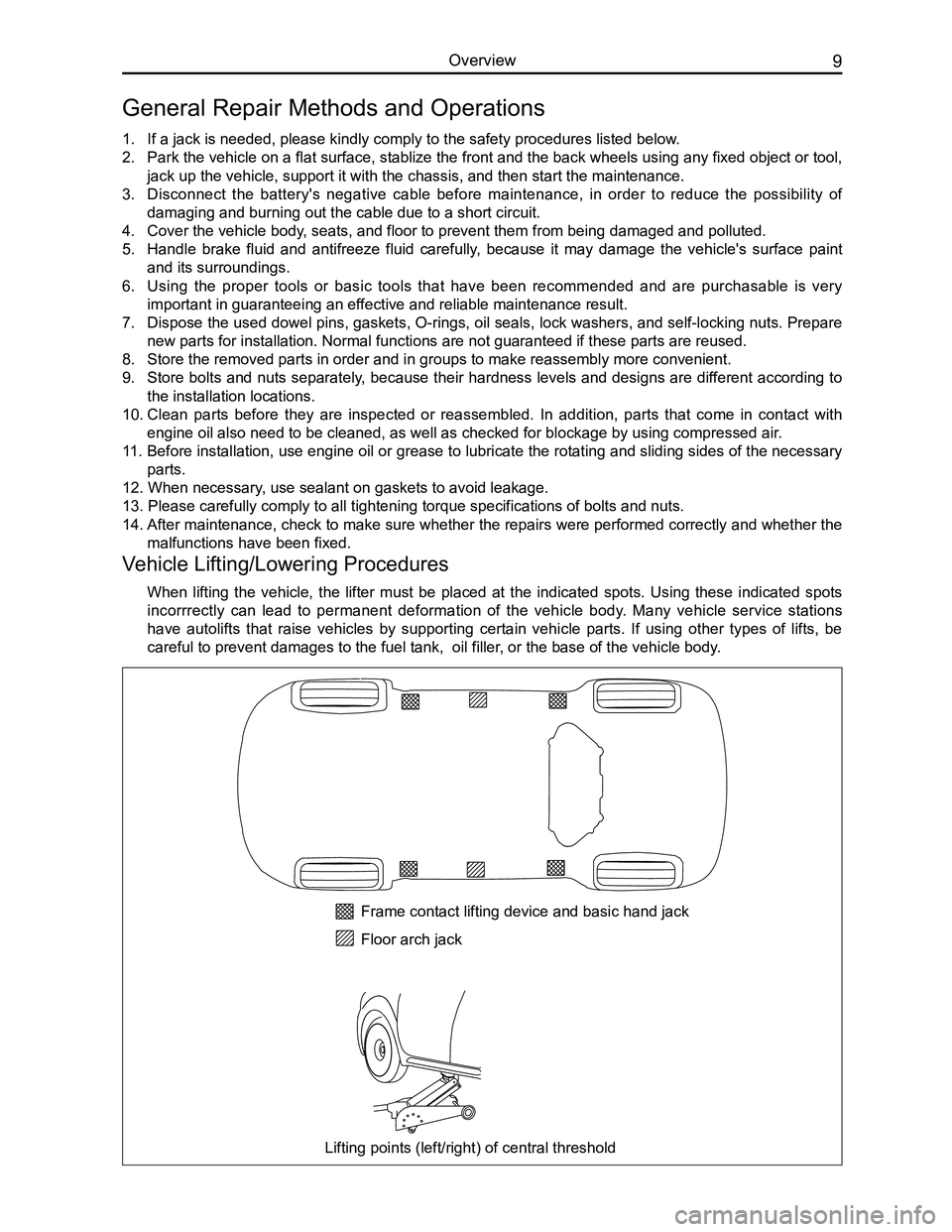
Vehicle Lifting/Lowering Procedures
When lifting the vehicle, the lifter must be placed at the indicated spots. Using these indicated spots
incorrrectly can lead to permanent deformation of the vehicle body. Many vehicle service stations
have autolifts that raise vehicles by supporting certain vehicle parts. If using other types of lifts, be
careful to prevent damages to the fuel tank, oil filler, or the base of the vehicle body.
Frame contact lifting device and basic hand jack
Floor arch jack
Lifting points (left/right) of central threshold
Page 25 of 281

Downloaded from www.Manualslib.com manuals search engine GWFLORID Maintenance Manual18
Torque Specifications for Key Operational Bolts
Any part that has a tightening torque requirement for fastening piece connections should be fastened according
to specifications, the tightening torque of fastening pieces that have no tightening torque specification should
satisfy the QC/T 518—1999 regulations.
Tightening torque for key operational bolts are shown in the table below.
No.Important fastening piece locationsFastening piece name
and model numberQuantity
Tightening
torque
(N·m)
1Chassis
1.01Left mount & left side memberHexagon bolt for flange face1112±10
Left mount & left mounting bracketHexagon bolt for flange face264±5
1.02Left mounting bracket & transmissionHexagon bolt for flange face364±5
Right mount & engineHexagon nut for flange face141±4
1.03Right mount & engineHexagon bolt for flange face264±5
Right mount & vehicle bodyHexagon bolt for flange face 264±5
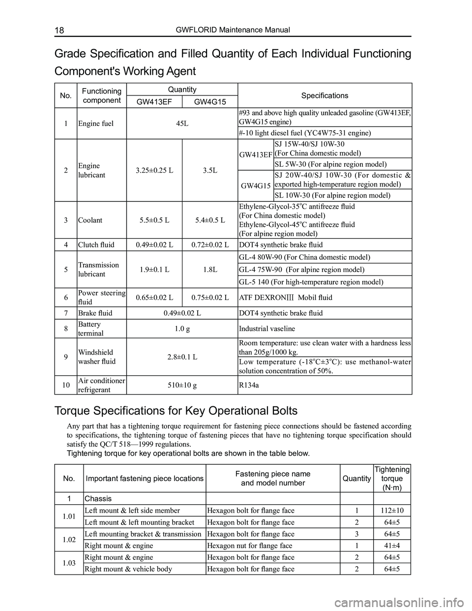
Grade Specification and Filled Quantity of Each Individual Functioning
Component's Working Agent
No.Functioning
component
QuantitySpecificationsGW413EFGW4G15
1Engine fuel45L
#93 and above high quality unleaded gasoline (GW413EF,
GW4G15 engine)
#-10 light diesel fuel (YC4W75-31 engine)
2Engine
lubricant3.25±0.25 L3.5L
GW413EF
SJ 15W-40/SJ 10W-30
(For China domestic model)
SL 5W-30 (For alpine region model)
GW4G15
SJ 20W-40/SJ 10W-30 (For domestic &
exported high-temperature region model)
SL 10W-30 (For alpine region model)
3Coolant5.5±0.5 L5.4±0.5 L
Ethylene-Glycol-35oC antifreeze fluid
(For China domestic model)
Ethylene-Glycol-45oC antifreeze fluid
(For alpine region model)
4Clutch fluid0.49±0.02 L0.72±0.02 LDOT4 synthetic brake fluid
5Transmission
lubricant1.9±0.1 L1.8L
GL-4 80W-90 (For China domestic model)
GL-4 75W-90 (For alpine region model)
GL-5 140 (For high-temperature region model)
6Power steering
fluid0.65±0.02 L0.75±0.02 LATF DEXRONⅢ Mobil fluid
7Brake fluid0.49±0.02 LDOT4 synthetic brake fluid
8Battery
terminal1.0 gIndustrial vaseline
9Windshield
washer fluid2.8±0.1 L
Room temperature: use clean water with a hardness less
than 205g/1000 kg.
Low temperature (-18oC±3oC): use methanol-water
solution concentration of 50%.
10Air conditioner
refrigerant510±10 gR134a
Page 186 of 281

Downloaded from www.Manualslib.com manuals search engine 179Electrical Accessories
Functional description and display program
1. This system will be activated within the first second after engaging the reverse gear. There will be two
beeps indicating the system is working properly.
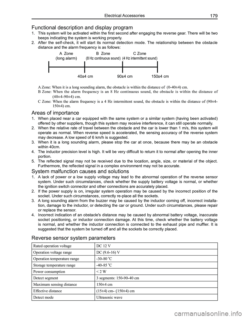
2. After the self-check, it will start its normal detection mode. The relationship between the obstacle
distance and the alarm frequency is as follows:
A Zone: When it is a long sounding alarm, the obstacle is within the distance of (0-40±4) cm.
B Zone: When the alarm frequency is an 8 Hz continuous sound, the obstacle is within the distance of
(40±4-90±4) cm.
C Zone: When the alarm frequency is a 4 Hz intermittent sound, the obstacle is within the distance of (90±4-
150±4) cm.
Areas of importance
1. When placed near a car equipped with the same system or a similar system (having been activated)
offered by other suppliers, though this system may receive interference, i\
t can still operate normally.
2. When the relative rate of travel between the obstacle and the car is lower than 1 m/s, this system will
operate as normal. When reverse speed is accelerated, the sensing accuracy of the reverse system
may decrease. A low speed of 6 km/h is suggested.
3. When it is a long sounding alarm, please stop the car at once, because there may be an obstacle
within 40cm.
4. The inductor precision level is high. It will be very difficult to return it to normal after opening the inner
portion.
5. The reflected signal may not be received due to the location, angle, size, or material of the object.
Furthermore, the reflected signal in a complex environment may not be ac\
curate.
System malfunction causes and solutions
1. A lack of power or a low supply voltage may lead to the abnormal operation of the reverse sensor
system. Under such circumstances, check whether the supply battery voltage is normal, or whether
the ignition switch connector and other connections are accurately place\
d.
2. If the power supply is on, irregular system operation may be caused by the incorrect position of the
socket. Under such circumstances, correctly re-place all the sockets.
3. A long sounding alarm from the buzzer may be caused by the inductor coming off, incorrect installa-
tion, damage to the inductor, or detecting the car or ground. Under such circumstances, please repair
or replace the sensor.
4. Incorrect indication of an obstacle's distance may be caused by abnormal battery voltage, inaccurate
socket positioning, or inductor connection damage. At this time, check whether the battery voltage
is normal, and whether the inductor connection is connected to the exhaust pipe and muffler. It is
suggested that the system be turned off and all the sockets be correctly placed.
Reverse sensor system parameters
Rated operation voltageDC 12 V
Operation voltage rangeDC (9.6-16) V
Operation temperature range-30-80 oC
Storage temperature range-40-85 oC
Power consumption< 2 W
Detect segment3 segments: 150-90-40 cm
Maximum sensing distance150±4 cm
Effective distance(15±4) cm- (150±4) cm
Detect modeUltrasonic wave
C Zone
(4 Hz intermittent sound)
40±4 cm 90±4 cm 150±4 cm
A Zone
(long alarm)
B Zone
(8 Hz continuous sound)
Page 208 of 281

Downloaded from www.Manualslib.com manuals search engine 201Electrical Accessories
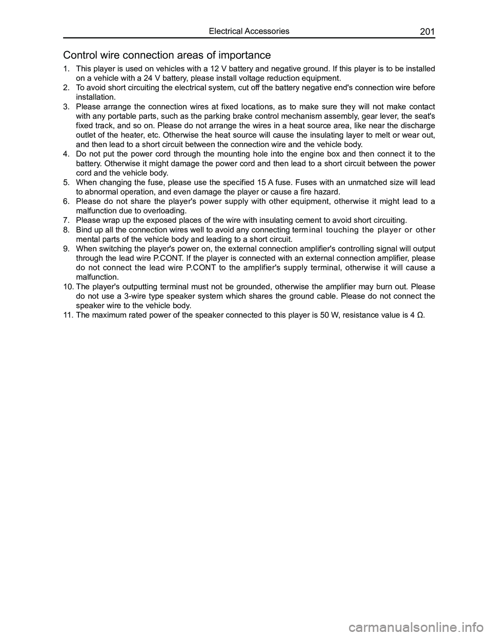
1. This player is used on vehicles with a 12 V battery and negative ground. If this player is to be installed
on a vehicle with a 24 V battery, please install voltage reduction equipment.
2. To avoid short circuiting the electrical system, cut off the battery negative end's connection wire before
installation.
3. Please arrange the connection wires at fixed locations, as to make sure they will not make contact
with any portable parts, such as the parking brake control mechanism assembly, gear lever, the seat's
fixed track, and so on. Please do not arrange the wires in a heat source area, like near the discharge
outlet of the heater, etc. Otherwise the heat source will cause the insulating layer to melt or wear out,
and then lead to a short circuit between the connection wire and the veh\
icle body.
4. Do not put the power cord through the mounting hole into the engine box and then connect it to the
battery. Otherwise it might damage the power cord and then lead to a short circuit between the power
cord and the vehicle body.
5. When changing the fuse, please use the specified 15 A fuse. Fuses with an unmatched size will lead
to abnormal operation, and even damage the player or cause a fire hazard\
.
6. Please do not share the player's power supply with other equipment, otherwise it might lead to a
malfunction due to overloading.
7. Please wrap up the exposed places of the wire with insulating cement to \
avoid short circuiting.
8. Bind up all the connection wires well to avoid any connecting term inal touching the player or other
mental parts of the vehicle body and leading to a short circuit.
9. When switching the player's power on, the external connection amplifier's controlling signal will output
through the lead wire P.CONT. If the player is connected with an external connection amplifier, please
do not connect the lead wire P.CONT to the amplifier's supply terminal, otherwise it will cause a
malfunction.
10. The player's outputting terminal must not be grounded, otherwise the amplifier may burn out. Please
do not use a 3-wire type speaker system which shares the ground cable. Please do not connect the
speaker wire to the vehicle body.
11. The maximum rated power of the speaker connected to this player is 50 W , resistance value is 4 Ω.
Control wire connection areas of importance