display GREAT WALL FLORID 2008 Service Manual
[x] Cancel search | Manufacturer: GREAT WALL, Model Year: 2008, Model line: FLORID, Model: GREAT WALL FLORID 2008Pages: 281, PDF Size: 43.97 MB
Page 99 of 281
Downloaded from www.Manualslib.com manuals search engine GWFLORID Maintenance Manual92
Wheel
General tire balancing procedures
Clean out the accumulated dirt and debris from the inside of the rim.
Warning:
The gravel on the tread must be eliminated to avoid flying out and injuring the operator when
undergoing rotational balancing. This is also a good way to acquire better balance. First thoroughly
inspect the tire's damaged condition, then according to the balancing device manufacture's
recommendations, carry out the balancing operation.
Off-vehicle balancing
Most off-vehicle balancers are more accurate and convenient than on-vehicle rotational balancers. They are
also able to perform dynamic (two sided) balancing. Although it does not correct drum brake and brake disc
imbalance like on-vehicle balancing, it achieves the same effect based on its accuracy.
On-vehicle balancing
On-vehicle balancing is different based on equipment and tool manufacturer. Therefore, when performing
balancing operations, be sure to comply to each manufacturer's operating\
instructions.
Warning: Control the wheel rotation speed to make sure the speedometer stays within 55 km/h.
This restriction is necessary because when a driven wheel slides while the other one stays still, the
speedometer will display only half of the actual wheel speed. When a wheel is sliding, be extremely
careful, because sliding wheels can reach very high speeds. This may lead to the tire rubber peeling
or differential damage, which may cause serious personal injury, or damage to the vehicle.
Tire installation and removal
• Install or remove tires with a tire changer. When operating machinery, make sure to comply to the machine
manufacturers operation manual. Please do not change tires merely with manual hand tools or tire installation
crowbars. This will damage the tire chafer or the vehicle wheel's rim.
• Use a wire brush or coarse steel wool to clean off grease and old rubber, as well as light rust or corrosion from
the rim tire bead's tire chafer seat. Before tire installation or removal, first use the indicated tire lubricant to
thoroughly lube the tire chafer portions one time.
• After installing the tire, inflate it to the specified pressure and make\
sure the tire bead is properly seated.
Warning: Do not over-inflate the tire. If the tire bead severally expands and exceeds the safety limit,
it may burst and cause serious personal injury. While inflating, do not exceed the specified pressure.
If the specified pressure does not allow the tire bead to sit properly, deflate the tire, re-lubricate, and
then re-inflate.
Spare tire usage
• Spare tire standard inflation pressure: 420 kPa.
• Spare tire pressure measurements should be taken under normal temperatur\
e conditions.
• After inflating the spare tire, soapy water should be used to check if the air nozzles core is leaking air, then
lock on the air nozzle cap.
• The spare tire should always be kept in a useable state. Check the air p\
ressure at least once a month.
• When the spare tire's working limit, indicated by the remaining pattern's depth, reaches 1.6 mm (and its pat-
tern groove bottom protrudes to the same level), for your safety, please stop using the spare tire.
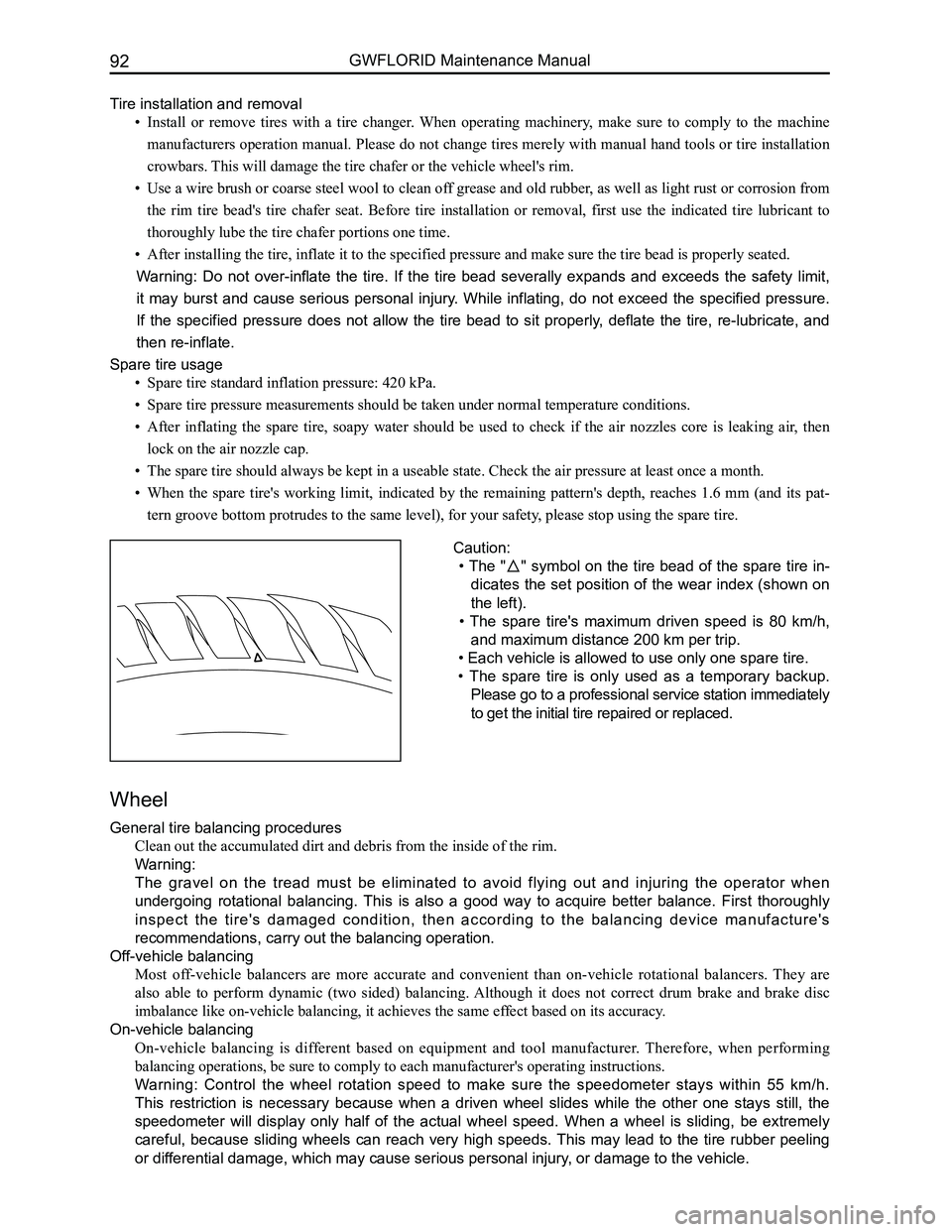
Caution:
• The "" symbol on the tire bead of the spare tire in-
dicates the set position of the wear index (shown on
the left).
• The spare tire's maximum driven speed is 80 km/h,
and maximum distance 200 km per trip.
• Each vehicle is allowed to use only one spare tire.
• The spare tire is only used as a temporary backup.
Please go to a professional service station immediately
to get the initial tire repaired or replaced.
Page 176 of 281
Downloaded from www.Manualslib.com manuals search engine 169Vehicle Body Electronic System
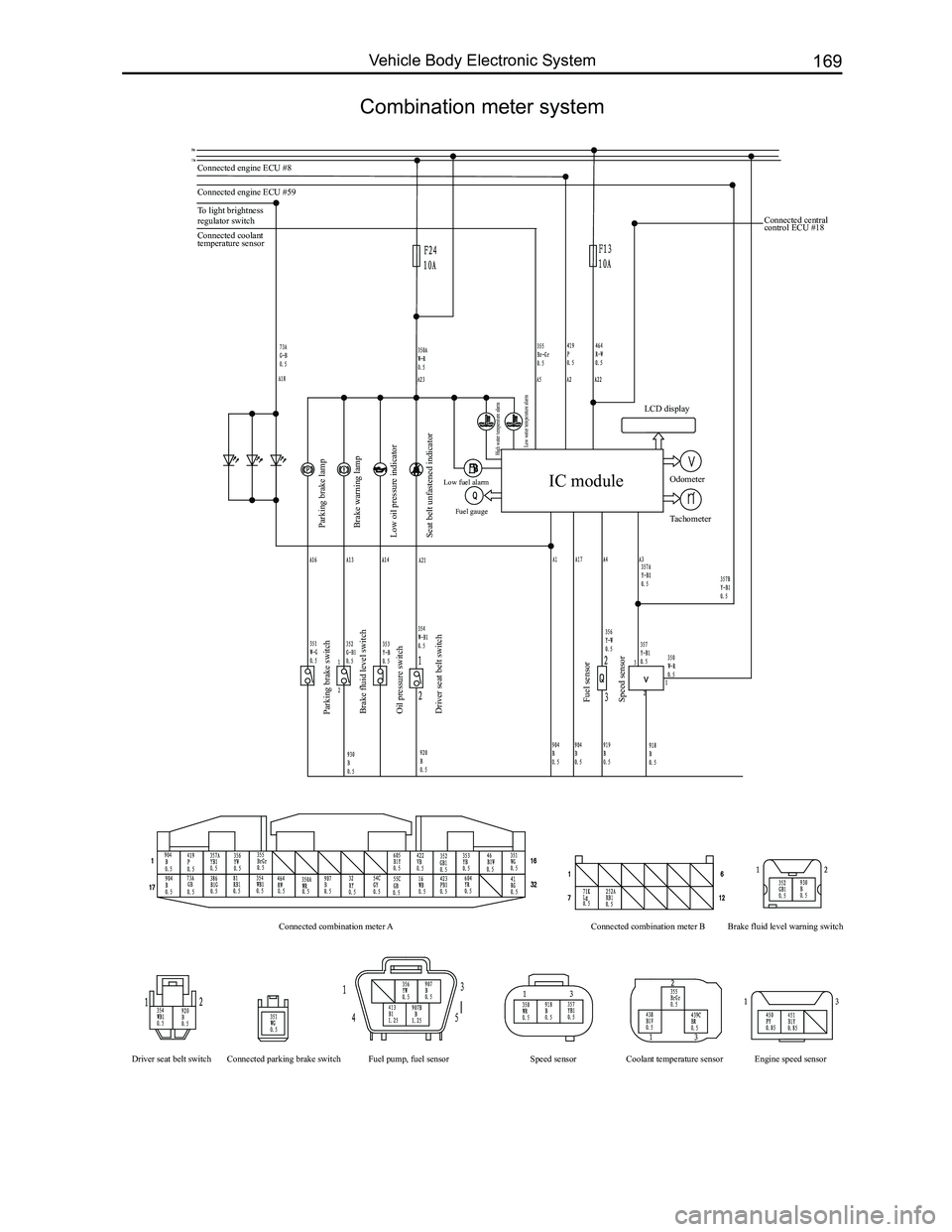
Combination meter system
Connected engine ECU #8
Connected engine ECU #59
To light brightness
regulator switch
Parking brake lamp
Parking brake switch
Brake fluid level switch
Oil pressure switch
Driver seat belt switch
Fuel sensor
Speed sensor
Connected combination meter A
Driver seat belt switch Connected parking brake switch Fuel pump, fuel sensor Coolant temperature sensor Engine speed sensor
Speed sensor Connected combination meter B
Brake fluid level warning switch
Brake warning lamp
Low oil pressure indicator
Seat belt unfastened indicator
Low fuel alarm Fuel gauge
High water temperature alarm
Low water temperature alarm
Connected coolant
temperature sensor Connected central
control ECU #18
IC module
LCD display
Odometer
Tachometer
Page 185 of 281
Downloaded from www.Manualslib.com manuals search engine GWFLORID Maintenance Manual178
Reverse Sensor
Reverse sensor operation (ultrasonic wave distance-measurement)
Sound is a kind of wave. Sound frequency that can be heard by human beings range from 20 Hz to 20 KHz.
Those that exceed 20 KHz are called ultrasonic waves. Since an ultrasonic wave is also a kind of sound, its
velocity in the air also equals the sound velocity of 340 m/s. Part of the ultrasonic wave will rebound when it
encounters an obstacle. So the distance between the sound source and the obstacle can be calculated according
to the sonic speed and the time difference between the emission of sound and the receipt of sound.
Reverse sensor system composition
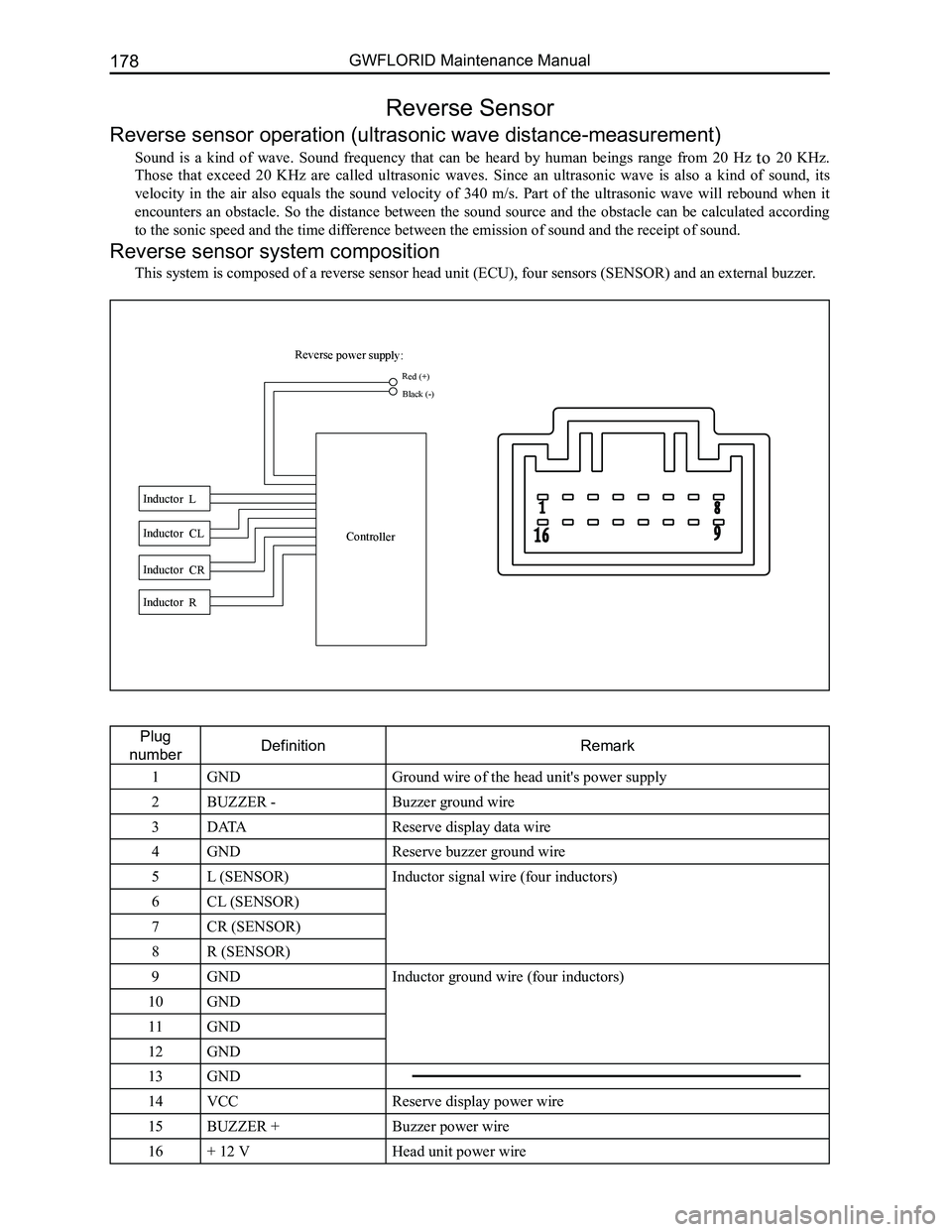
This system is composed of a reverse sensor head unit (ECU), four sensors (SENSOR) and an external buzzer.
Plug
numberDefinitionRemark
1GNDGround wire of the head unit's power supply
2BUZZER -Buzzer ground wire
3DATAReserve display data wire
4GNDReserve buzzer ground wire
5L (SENSOR)Inductor signal wire (four inductors)
6CL (SENSOR)
7CR (SENSOR)
8R (SENSOR)
9GNDInductor ground wire (four inductors)
10GND
11GND
12GND
13GND
14VCCReserve display power wire
15BUZZER +Buzzer power wire
16+ 12 VHead unit power wire
Reverse power supply:
Inductor L Inductor CL
Inductor CR Inductor R Controller
Red (+)
Black (-)
Page 186 of 281
Downloaded from www.Manualslib.com manuals search engine 179Electrical Accessories
Functional description and display program
1. This system will be activated within the first second after engaging the reverse gear. There will be two
beeps indicating the system is working properly.
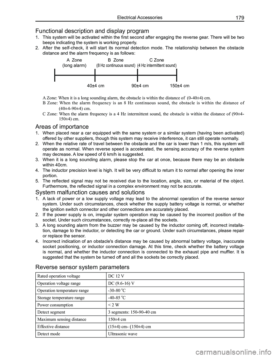
2. After the self-check, it will start its normal detection mode. The relationship between the obstacle
distance and the alarm frequency is as follows:
A Zone: When it is a long sounding alarm, the obstacle is within the distance of (0-40±4) cm.
B Zone: When the alarm frequency is an 8 Hz continuous sound, the obstacle is within the distance of
(40±4-90±4) cm.
C Zone: When the alarm frequency is a 4 Hz intermittent sound, the obstacle is within the distance of (90±4-
150±4) cm.
Areas of importance
1. When placed near a car equipped with the same system or a similar system (having been activated)
offered by other suppliers, though this system may receive interference, i\
t can still operate normally.
2. When the relative rate of travel between the obstacle and the car is lower than 1 m/s, this system will
operate as normal. When reverse speed is accelerated, the sensing accuracy of the reverse system
may decrease. A low speed of 6 km/h is suggested.
3. When it is a long sounding alarm, please stop the car at once, because there may be an obstacle
within 40cm.
4. The inductor precision level is high. It will be very difficult to return it to normal after opening the inner
portion.
5. The reflected signal may not be received due to the location, angle, size, or material of the object.
Furthermore, the reflected signal in a complex environment may not be ac\
curate.
System malfunction causes and solutions
1. A lack of power or a low supply voltage may lead to the abnormal operation of the reverse sensor
system. Under such circumstances, check whether the supply battery voltage is normal, or whether
the ignition switch connector and other connections are accurately place\
d.
2. If the power supply is on, irregular system operation may be caused by the incorrect position of the
socket. Under such circumstances, correctly re-place all the sockets.
3. A long sounding alarm from the buzzer may be caused by the inductor coming off, incorrect installa-
tion, damage to the inductor, or detecting the car or ground. Under such circumstances, please repair
or replace the sensor.
4. Incorrect indication of an obstacle's distance may be caused by abnormal battery voltage, inaccurate
socket positioning, or inductor connection damage. At this time, check whether the battery voltage
is normal, and whether the inductor connection is connected to the exhaust pipe and muffler. It is
suggested that the system be turned off and all the sockets be correctly placed.
Reverse sensor system parameters
Rated operation voltageDC 12 V
Operation voltage rangeDC (9.6-16) V
Operation temperature range-30-80 oC
Storage temperature range-40-85 oC
Power consumption< 2 W
Detect segment3 segments: 150-90-40 cm
Maximum sensing distance150±4 cm
Effective distance(15±4) cm- (150±4) cm
Detect modeUltrasonic wave
C Zone
(4 Hz intermittent sound)
40±4 cm 90±4 cm 150±4 cm
A Zone
(long alarm)
B Zone
(8 Hz continuous sound)
Page 198 of 281
Downloaded from www.Manualslib.com manuals search engine 191Electrical Accessories
4. Security system component replacement
When a failure appears in one of the immobilizer system components, this component must be replaced. After
the replacement, perform matching on the immobilizer system again.
Only changing the coil
There is no need to match the immobilizer system again.
Only changing the key (theft deterrent transponder assembly)
(a) Get the vehicle's PIN code from the code located inside the burglar-proof classified envelope
(b) Connect the scanner with the vehicle's diagnostic connection
(c) Insert the key into the ignition lock and turn it to the "ON" position
(d) Check whether the key is legal and matched. If it is illegal or already been matched, then it cannot be
matched again, but will have to be replaced
(e) Input the PIN code with the scanner
(f) Erase the damaged lost key's information
(g) Match the new key according to the scanner's prompt
(h) If it is necessary to match another key, insert the key, and after resetting the scanner, operate according to
steps c, d, e, and g.
Caution: Make sure the key is legal and hasn't been matched before learning the key. Otherwise, the
immobilizer system won’t successfully match or the scanner will display that it has been matched but
the electrojet's validation is not available.
Only replacing the theft deterrent controller assembly
(a) Get the vehicle's PIN code from the code inside the burglar-proof classified envelope
(b) Turn off the ignition switch, and replace with an unmatched new theft deterrent controller or reset the theft
deterrent controller
(c) Insert the key into the ignition lock and turn it to the ON position
(d) Input the PIN code with the scanner
(e) Match the theft deterrent controller assembly according to the scanner prompts
(f) Because the theft deterrent controller is new, there is no VIN and original key information stored in it. It
will need the VIN inputted and must be matched with the original key, otherwise the original key will not
work.
Caution:
(a) Replace the new alarm remote controller or reset the alarm remote controller, or the alarm re-
mote controller system matching can not be completed.
(b) Select "Read EMS to alarm remote controller", not "Read alarm remote controller to EMS", or it
will make the transponder inoperable.
Only replacing the engine ECU
(a) Get the vehicle's PIN code from the code inside the burglar-proof classified envelope
(b) Turn off the ignition switch, and replace with a new non-matched or reset ECU
(c) Insert the key into the ignition lock and turn it to the ON position
(d) Input the PIN code with the scanner
(e) Match the ECU according to the prompts on the scanner, and complete the ECU and theft deterrent
controller matching.
Caution:
(a) Make sure to replace it with a new or reset ECU, otherwise the immobilizer system matching can-
not be completed.
(b) Select the menu of "Read EMS to theft deterrent controller", but not "Read theft deterrent control-
ler to EMS", or it will make the transponder inoperable.
Replacing the theft deterrent controller and EMS controller at the same\
time
If both the theft deterrent controller and EMS controller need to be changed at the same time, then the transpon-
der that has been matched must also be replaced, otherwise the immobilizer system matching cannot be com-
pleted. The immobilizer system needs to be re-matched after being replace.
Matching after sales stage
Problems caused by lost keys or immobilizer system failures requires a duplicate key, replaced parts, etc. These
problems cannot be solved without re-matching the immobilizer system's parts. During the matching, input the
correct PIN code with scanner. Specific possible problems and matching methods the maintenance station may
encounter are as follows:
1. Match an empty key:
(a) Properly connect the engine ECU and the theft deterrent controller, and then insert the key to be matched,
and switch the ignition switch to the ON position
Page 201 of 281
Downloaded from www.Manualslib.com manuals search engine GWFLORID Maintenance Manual194
Display characterMalfunctionSolutions
ERR3Disc is placed upside downEject the disc and reload
ERR4Incompatible disc file or formatCheck the disc format
ERR1
ERR1Disc structure errorEject the disc and replay
Trouble code
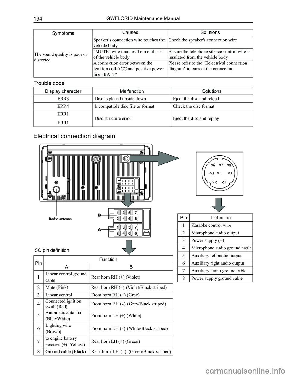
Electrical connection diagram
SymptomsCausesSolutions
The sound quality is poor or
distorted
Speaker's connection wire touches the
vehicle body
Check the speaker's connection wire
"MUTE" wire touches the metal parts
of the vehicle body
Ensure the telephone silence control wire is
insulated from the vehicle body
A connection error between the
ignition coil ACC and positive power
line "BATT"
Please refer to the "Eelectrical connection
diagram" to correct the connection
Radio antenna
12
345
678
PinDefinition
1Karaoke control wire
2Microphone audio output
3Power supply (+)
4Microphone audio ground cable
5Auxiliary left audio output
6Auxiliary right audio output
7Auxiliary audio ground cable
8Power supply ground cable
PinFunction
AB
1Linear control ground
cableRear horn RH (+) (Violet)
2Mute (Pink)Rear horn RH ( - ) (Violet/Black striped)
3Linear controlFront horn RH (+) (Grey)
4Connected ignition
swith (Red)Front horn RH ( - ) (Grey/Black striped)
5Automatic antenna
(Blue/White)Front horn LH (+) (White)
6Lighting wire
(Brown)Front horn LH ( - ) (White/Black striped)
7to engine battery
positive (+) (Yellow)Rear horn LH (+) (Green)
8Ground cable (Black)Rear horn LH ( - ) (Green/Black striped)
ISO pin definition
Page 204 of 281
Downloaded from www.Manualslib.com manuals search engine 197Electrical Accessories
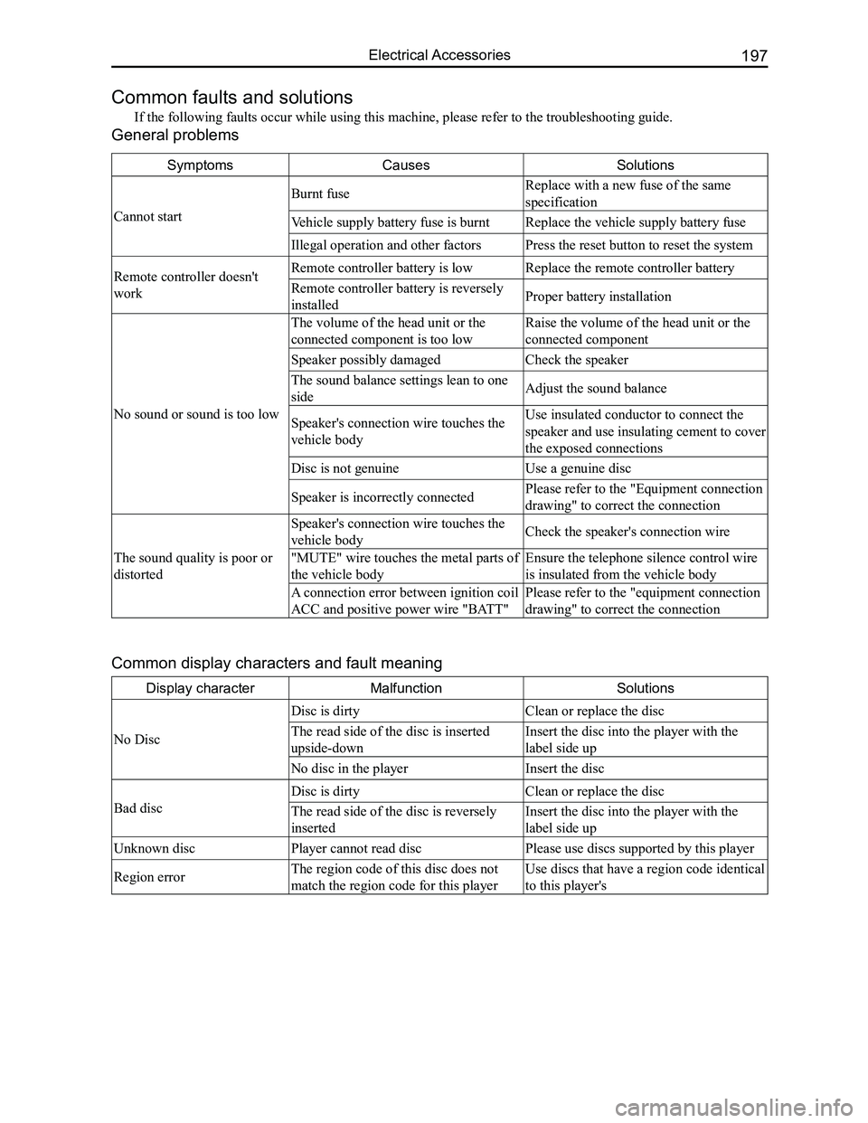
Common faults and solutions
If the following faults occur while using this machine, please refer to \
the troubleshooting guide.
General problems
SymptomsCausesSolutions
Cannot start
Burnt fuseReplace with a new fuse of the same
specification
Vehicle supply battery fuse is burntReplace the vehicle supply battery fuse
Illegal operation and other factorsPress the reset button to reset the system
Remote controller doesn't
work
Remote controller battery is lowReplace the remote controller battery
Remote controller battery is reversely
installedProper battery installation
No sound or sound is too low
The volume of the head unit or the
connected component is too low
Raise the volume of the head unit or the
connected component
Speaker possibly damagedCheck the speaker
The sound balance settings lean to one
sideAdjust the sound balance
Speaker's connection wire touches the
vehicle body
Use insulated conductor to connect the
speaker and use insulating cement to cover
the exposed connections
Disc is not genuineUse a genuine disc
Speaker is incorrectly connectedPlease refer to the "Equipment connection
drawing" to correct the connection
The sound quality is poor or
distorted
Speaker's connection wire touches the
vehicle bodyCheck the speaker's connection wire
"MUTE" wire touches the metal parts of
the vehicle body
Ensure the telephone silence control wire
is insulated from the vehicle body
A connection error between ignition coil
ACC and positive power wire "BATT"
Please refer to the "equipment connection
drawing" to correct the connection
Common display characters and fault meaning
Display characterMalfunctionSolutions
No Disc
Disc is dirtyClean or replace the disc
The read side of the disc is inserted
upside-down
Insert the disc into the player with the
label side up
No disc in the playerInsert the disc
Bad disc
Disc is dirtyClean or replace the disc
The read side of the disc is reversely
inserted
Insert the disc into the player with the
label side up
Unknown disc Player cannot read discPlease use discs supported by this player
Region error The region code of this disc does not
match the region code for this player
Use discs that have a region code identical
to this player's
Page 205 of 281
Downloaded from www.Manualslib.com manuals search engine GWFLORID Maintenance Manual198
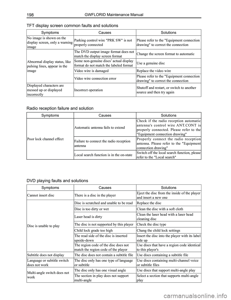
TFT display screen common faults and solutions
SymptomsCausesSolutions
No image is shown on the
display screen, only a warning
image
Parking control wire "PRK SW" is not
properly connected
Please refer to the "Equipment connection
drawing" to correct the connection
Abnormal display status, like
pulsing lines, appear in the
image
The DVD output image format does not
match the display screen formatChange the screen format to automatic
Some non-genuine discs’ actual display
format do not match the labeled formatUse a genuine disc
Video wire is damaged Replace the video wire
Video wire connection error Please refer to the "Equipment connection
drawing" to correct the connection
Displayed characters are
messed up or displayed
incorrectly
Incorrect operation Shutoff and restart, or switch to another
source and then try again
SymptomsCausesSolutions
Poor lock channel effect
Automatic antenna fails to extend
Check if the radio reception automatic
a n t e n n a ' s c o n t r o l w i r e A N T. C O N T i s
properly connected. Please refer to the
"Equipment connection drawing"
Failure to connect the radio reception
antenna
P r o p e r l y c o n n e c t t h e r a d i o r e c e p t i o n
antenna. Please refer to the "Equipment
connection drawing"
Local search function is in the on-state Switch off the local search function, please
refer to the "Local search"
Radio reception failure and solution
DVD playing faults and solutions
SymptomsCausesSolutions
Cannot insert discThere is a disc in the playerEject the disc from the inside of the player
and insert a new one
Disc is unable to play
Disc is scratched and unable to be readReplace the disc
Disc is too dirty or wetClean the disc with a soft cloth
Laser head is dirtyClean the laser head with a laser head
cleaning disc
The disc is not supported by this playerCheck the disc type
Child lock grade too highChang the child lock settings
The read side of the disc is inserted
upside-down
Insert the disc into the player with its label
side up
The region code of the disc does not
match the region code of the player
Use discs that have a region code identical
to this player's
Subtitle does not displayThe disc does not contain a subtitle fileUse discs containing a subtitle file
Language or subtitle switch
does not work
The disc only has one type of language
or subtitle
Use discs containing multi-channel voice
or subtitle files
Multi-angle switch does not
work
The disc only has one visual angleUse discs that support multi-angle play
The section in play does not support
multi-angle
Select a section that supports multi-angle
play
Page 206 of 281

Downloaded from www.Manualslib.com manuals search engine 199Electrical Accessories
SymptomsCausesSolutions
Image is blurred and distortedThe disc is copy protected
The player is compatible with the copy
system, so if the disc is copy protected, it
may not be able to play, and is not a problem
with the player
PBC function has no effect
when playing a VCD discThe disc contains no PBC functionUse discs that support the PBC function
Repeat function and album/
time search are unavailablePBC is set to onTurn off the PBC function
SymptomsCausesSolutions
Cannot play MP3
Disc is scratched or dirty Clean the disc with soft cloth
Laser head is dirtyClean the laser head with a laser head
cleaning disc
The disc is not supported by this playerPlease use discs supported by this player
The read side of the disc is inserted
upside-down
Insert the disc into the player with its label
side up
The sound is not smooth when
playing MP3
The disc is too dirty or scratchedClean or replace the disc
Partial content is damagedReplace the disc
Bad record conditionRe-record the disc
Name of MP3 file is not
displayed normallyIrregular file nameDo not use Chinese names
MP3 playing faults and solution
Page 225 of 281
Downloaded from www.Manualslib.com manuals search engine GWFLORID Maintenance Manual218
detection but also during the diagnostic detection cycle. However, if a short circuit on the power supply causes
a malfunction, and the low-end transistor is opened while malfunctioned, the low-end transistor can only be
detected when starting up detection, as to avoid faulty execution.
(b) Ignition voltage is provided by a pressure increase converter.
(c) Acceleration sensor performs self-detection when starting up detection.
(d) Allowed offset range of the acceleration sensor during a diagnostic cycle.
(e) Microcontroller includes AD converter, ROM, RAM, etc.
(f) Security sensor status.
Caution: There is a short-circuiting bar inside the squib circuit connector. When the connector is not
connected, the short circuit happens between the squib circuit's terminal (+) and terminal (-), as to
avoid faulty deployment caused by static electricity. When the connector is bad and the short-circuiting
bar is connected, the fault symptom may not be eliminated.
4. Clear the trouble code
When the X-431 diagnostic instrument receives the "Clear the trouble code" order sent through the serial inter-
face, the trouble code inside the ECU will be cleared. However, if an internal trouble code is recorded or has a
collision record, it will not carry out this order.
(a) Malfunction status display.
When the working voltage is supplied to the SRS-ECU through a battery, the SRS-ECU will light the warning
lamp to inspect the light bulbs. During the initialization stage, the warning lamp will remain on for 6-7 s, and
in order to inform the driver that the system has a malfunction, the warning lamp will continue to remain on
after the working voltage is supplied. If the history trouble code’s quantity is less than 16, the warning lamp
will remain lit for 6-7 s after turning the ignition on and then turn off automatically. If the history trouble code’s
quantity is 16 and the current malfunction appears, it will be recorded and the first history malfunction record
will be automatically removed.
(b) Malfunction indicator.
When the system has malfunctioned, the warning lamp will be always on.
A displayed or history malfunction can only be reset by service personnel. A SRS-ECU internal malfunction or
malfunction’s "collision record" cannot be reset. In this situation, the SRS-ECU mus\
t be replaced.
(c) Microcontroller - independent warning lamp is lit.
The controller has a self-diagnosis function. If the inner controller malfunctions, the warning lamp will always
be on.
(d) If the airbag warning lamp is always on, please inspect it according to the following steps.
The first step of inspecting any of the malfunctions is to detect the malfunction’s position with a scanner. Then
carry out the inspection using the corresponding part’s inspection method. If the scanning result is an internal
malfunction or having to do with airbag execution, the SRS-ECU can be di\
rectly replaced.