AUX GREAT WALL FLORID 2008 Service Manual
[x] Cancel search | Manufacturer: GREAT WALL, Model Year: 2008, Model line: FLORID, Model: GREAT WALL FLORID 2008Pages: 281, PDF Size: 43.97 MB
Page 22 of 281
Downloaded from www.Manualslib.com manuals search engine 15Overall Parameters
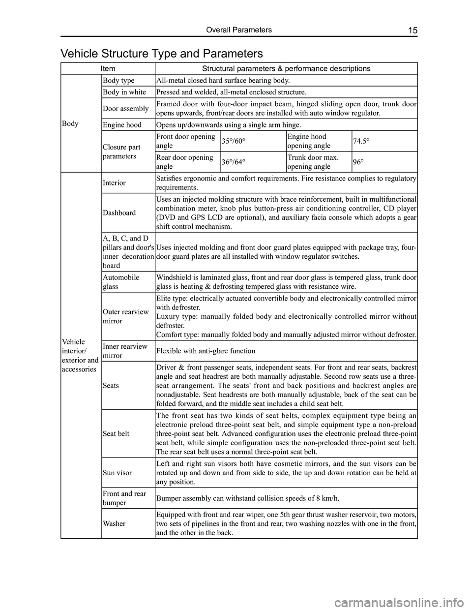
Vehicle Structure Type and Parameters
ItemStructural parameters & performance descriptions
Body
Body typeAll-metal closed hard surface bearing body.
Body in whitePressed and welded, all-metal enclosed structure.
Door assemblyFramed door with four-door impact beam, hinged sliding open door, trunk door
opens upwards, front/rear doors are installed with auto window regulator\
.
Engine hoodOpens up/downwards using a single arm hinge.
Closure part
parameters
Front door opening
angle35°/60°Engine hood
opening angle74.5°
Rear door opening
angle36°/64°Trunk door max.
opening angle96°
Vehicle
interior/
exterior and
accessories
Interior Satisfies ergonomic and comfort requirements. Fire resistance complies to regulatory
requirements.
Dashboard
Uses an injected molding structure with brace reinforcement, built in multifunctional
combination meter, knob plus button-press air conditioning controller, CD player
(DVD and GPS LCD are optional), and auxiliary facia console which adopts a gear
shift control mechanism.
A, B, C, and D
pillars and door's
inner decoration
board
Uses injected molding and front door guard plates equipped with package tray, four-
door guard plates are all installed with window regulator switches.
Automobile
glass
Windshield is laminated glass, front and rear door glass is tempered glass, trunk door
glass is heating & defrosting tempered glass with resistance wire.
Outer rearview
mirror
Elite type: electrically actuated convertible body and electronically controlled mirror
with defroster.
Luxury type: manually folded body and electronically controlled mirror without
defroster.
Comfort type: manually folded body and manually adjusted mirror without \
defroster.
Inner rearview
mirrorFlexible with anti-glare function
Seats
Driver & front passenger seats, independent seats. For front and rear seats, backrest
angle and seat headrest are both manually adjustable. Second row seats use a three-
seat arrangement. The seats' front and back positions and backrest angles are
nonadjustable. Seat headrests are both manually adjustable, back of the seat can be
folded forward, and the middle seat includes a child seat belt.
Seat belt
The front seat has two kinds of seat belts, complex equipment type being an
electronic preload three-point seat belt, and simple equipment type a non-preload
three-point seat belt. Advanced configuration uses the electronic preload three-point
seat belt, while simple configuration uses the non-preloaded three-point seat belt.
The rear seat belt uses a normal three-point seat belt.
Sun visor
Left and right sun visors both have cosmetic mirrors, and the sun visors can be
rotated up and down and from side to side, the up and down rotation can be held at
any position.
Front and rear
bumperBumper assembly can withstand collision speeds of 8 km/h.
Washer
Equipped with front and rear wiper, one 5th gear thrust washer reservoir, two motors,
two sets of pipelines in the front and rear, two washing nozzles with one in the front,
and the other in the back.
Page 24 of 281
Downloaded from www.Manualslib.com manuals search engine 17Overall Parameters
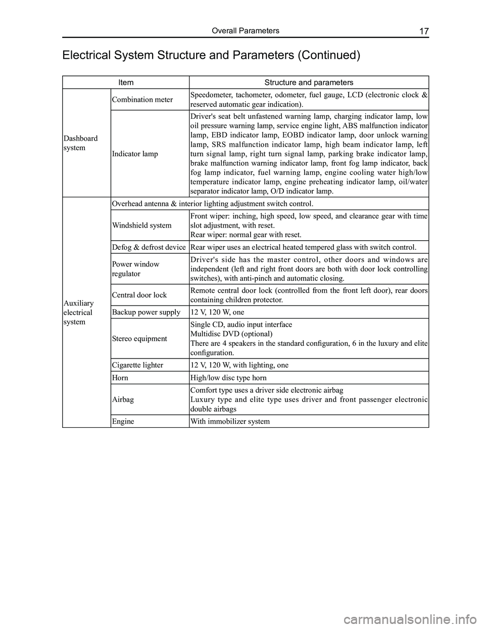
ItemStructure and parameters
Dashboard
system
Combination meter Speedometer, tachometer, odometer, fuel gauge, LCD (electronic clock &
reserved automatic gear indication).
Indicator lamp
Driver's seat belt unfastened warning lamp, charging indicator lamp, low
oil pressure warning lamp, service engine light, ABS malfunction indicator
lamp, EBD indicator lamp, EOBD indicator lamp, door unlock warning
lamp, SRS malfunction indicator lamp, high beam indicator lamp, left
turn signal lamp, right turn signal lamp, parking brake indicator lamp,
brake malfunction warning indicator lamp, front fog lamp indicator, back
fog lamp indicator, fuel warning lamp, engine cooling water high/low
temperature indicator lamp, engine preheating indicator lamp, oil/water
separator indicator lamp, O/D indicator lamp.
Auxiliary
electrical
system
Overhead antenna & interior lighting adjustment switch control.
Windshield system
Front wiper: inching, high speed, low speed, and clearance gear with time
slot adjustment, with reset.
Rear wiper: normal gear with reset.
Defog & defrost deviceRear wiper uses an electrical heated tempered glass with switch control.\
Power window
regulator
D r i v e r ' s s i d e h a s t h e m a s t e r c o n t r o l , o t h e r d o o r s a n d w i n d o w s a r e
independent (left and right front doors are both with door lock controlling
switches), with anti-pinch and automatic closing.
Central door lockRemote central door lock (controlled from the front left door), rear doors
containing children protector.
Backup power supply12 V, 120 W, one
Stereo equipment
Single CD, audio input interface
Multidisc DVD (optional)
There are 4 speakers in the standard configuration, 6 in the luxury and elite
configuration.
Cigarette lighter12 V, 120 W, with lighting, one
HornHigh/low disc type horn
Airbag
Comfort type uses a driver side electronic airbag
Luxury type and elite type uses driver and front passenger electronic
double airbags
EngineWith immobilizer system
Electrical System Structure and Parameters (Continued)
Page 109 of 281
Downloaded from www.Manualslib.com manuals search engine GWFLORID Maintenance Manual102
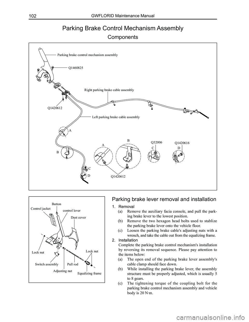
Parking Brake Control Mechanism Assembly
Components
Parking brake lever removal and installation
1. Removal
(a) Remove the auxiliary facia console, and pull the park-
ing brake lever to the lowest position.
(b) Remove the two hexagon head bolts used to stablize
the parking brake lever onto the vehicle floor.
(c) Loosen the parking brake cable's adjusting nuts with a
wrench, and take the cable out from the equalizing frame.
2. Installation
Complete the parking brake control mechanism's installation
by reversing its removal sequence. Please pay attention to
the items below:
(a) The open end of the parking brake lever assembly's
cable clamp should face down.
(b) While installing the parking brake lever, the assembly
structure must be properly adjusted, which is usually 5
to 8 gears.
(c) The tightening torque of the coupling bolt for the
parking brake control mechanism assembly and vehicle
body is 20 N·m.
A
B
C
D
Q1420612
Q1460825
Q32006Q1420616
Parking brake control mechanism assembly
Q1420612
A
B
CD
Left parking brake cable assembly
Right parking brake cable assembly
Button
control lever Control jacket
Dust cover
Lock nutLock nut
Switch assembly
Adjusting nutEqualizing frame
Pull rod
Page 183 of 281
Downloaded from www.Manualslib.com manuals search engine GWFLORID Maintenance Manual176
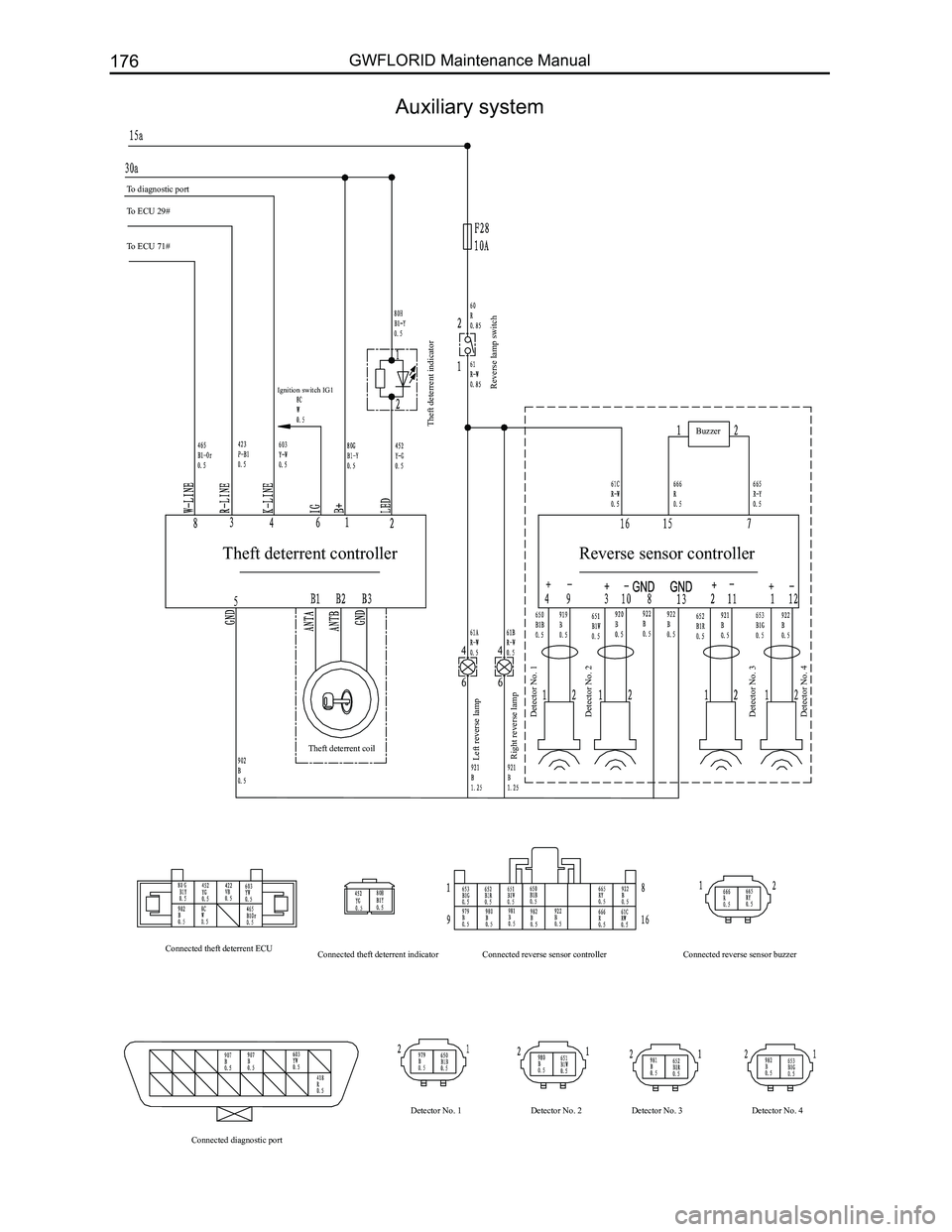
Auxiliary system
To diagnostic port
To ECU 29#
To ECU 71#
Theft deterrent indicatorReverse lamp switch
Left reverse lamp
Right reverse lamp Detector No. 1
Detector No. 2
Detector No. 3
Detector No. 4
Theft deterrent coil
Connected theft deterrent ECU Connected diagnostic port Detector No. 1
Detector No. 2Detector No. 3 Detector No. 4
Connected theft deterrent indicator
Connected reverse sensor controller Connected reverse sensor buzzerBuzzer
Ignition switch IG1
Theft deterrent controller
Reverse sensor controller
Page 201 of 281
Downloaded from www.Manualslib.com manuals search engine GWFLORID Maintenance Manual194
Display characterMalfunctionSolutions
ERR3Disc is placed upside downEject the disc and reload
ERR4Incompatible disc file or formatCheck the disc format
ERR1
ERR1Disc structure errorEject the disc and replay
Trouble code
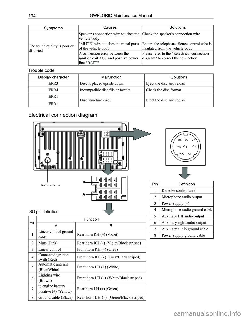
Electrical connection diagram
SymptomsCausesSolutions
The sound quality is poor or
distorted
Speaker's connection wire touches the
vehicle body
Check the speaker's connection wire
"MUTE" wire touches the metal parts
of the vehicle body
Ensure the telephone silence control wire is
insulated from the vehicle body
A connection error between the
ignition coil ACC and positive power
line "BATT"
Please refer to the "Eelectrical connection
diagram" to correct the connection
Radio antenna
12
345
678
PinDefinition
1Karaoke control wire
2Microphone audio output
3Power supply (+)
4Microphone audio ground cable
5Auxiliary left audio output
6Auxiliary right audio output
7Auxiliary audio ground cable
8Power supply ground cable
PinFunction
AB
1Linear control ground
cableRear horn RH (+) (Violet)
2Mute (Pink)Rear horn RH ( - ) (Violet/Black striped)
3Linear controlFront horn RH (+) (Grey)
4Connected ignition
swith (Red)Front horn RH ( - ) (Grey/Black striped)
5Automatic antenna
(Blue/White)Front horn LH (+) (White)
6Lighting wire
(Brown)Front horn LH ( - ) (White/Black striped)
7to engine battery
positive (+) (Yellow)Rear horn LH (+) (Green)
8Ground cable (Black)Rear horn LH ( - ) (Green/Black striped)
ISO pin definition
Page 203 of 281
Downloaded from www.Manualslib.com manuals search engine GWFLORID Maintenance Manual196
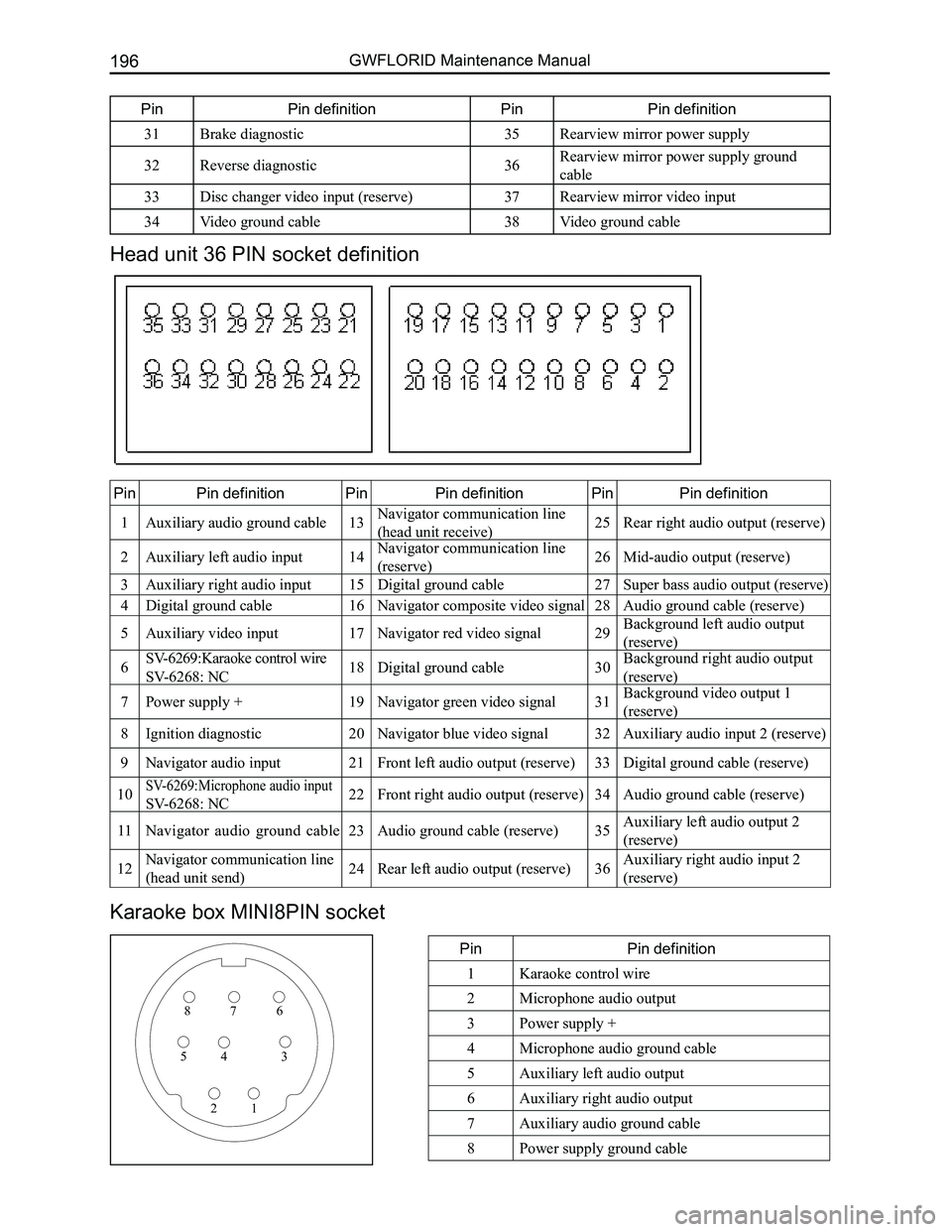
Head unit 36 PIN socket definition
PinPin definitionPinPin definitionPinPin definition
1Auxiliary audio ground cable13Navigator communication line
(head unit receive)25Rear right audio output (reserve)
2Auxiliary left audio input14Navigator communication line
(reserve)26Mid-audio output (reserve)
3Auxiliary right audio input15Digital ground cable27Super bass audio output (reserve)
4Digital ground cable16Navigator composite video signal28Audio ground cable (reserve)
5Auxiliary video input17Navigator red video signal29Background left audio output
(reserve)
6SV-6269:Karaoke control wire
SV-6268: NC18Digital ground cable30Background right audio output
(reserve)
7Power supply +19Navigator green video signal31Background video output 1
(reserve)
8Ignition diagnostic20Navigator blue video signal32Auxiliary audio input 2 (reserve)
9Navigator audio input21Front left audio output (reserve)33Digital ground cable (reserve)
10SV-6269:Microphone audio input
SV-6268: NC22Front right audio output (reserve)34Audio ground cable (reserve)
11Navigator audio ground cable23Audio ground cable (reserve)35Auxiliary left audio output 2
(reserve)
12Navigator communication line
(head unit send)24Rear left audio output (reserve)36Auxiliary right audio input 2
(reserve)
Karaoke box MINI8PIN socket
PinPin definition
1Karaoke control wire
2Microphone audio output
3Power supply +
4Microphone audio ground cable
5Auxiliary left audio output
6Auxiliary right audio output
7Auxiliary audio ground cable
8Power supply ground cable
876
345
21
PinPin definitionPinPin definition
31Brake diagnostic35Rearview mirror power supply
32Reverse diagnostic36Rearview mirror power supply ground
cable
33Disc changer video input (reserve)37Rearview mirror video input
34Video ground cable38Video ground cable
Page 207 of 281
Downloaded from www.Manualslib.com manuals search engine GWFLORID Maintenance Manual200
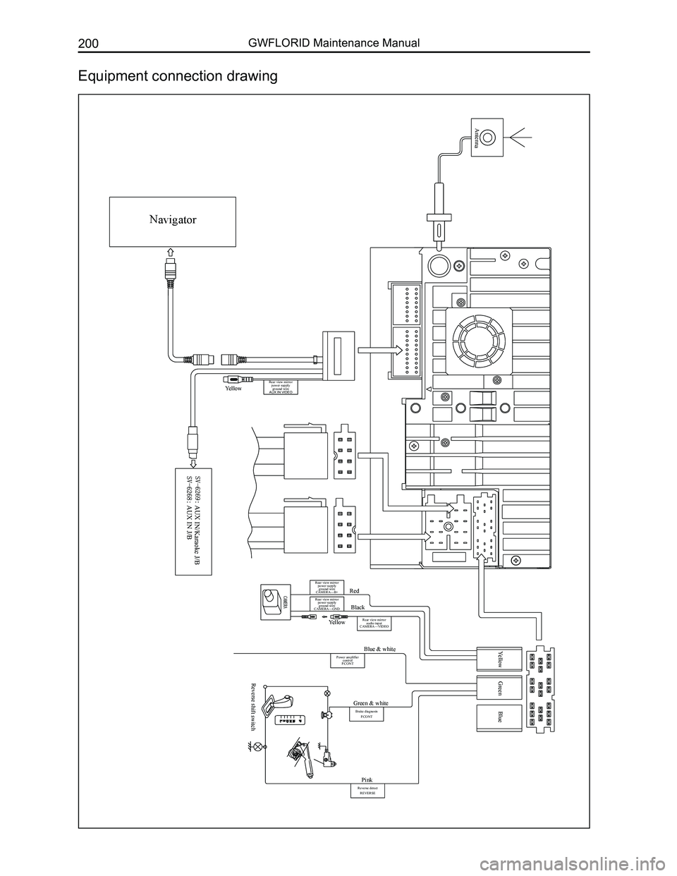
Equipment connection drawing
Navigator
Antenna
Yellow
AUX IN/Karaoke J/B AUX IN J/B
Red
Black
Yellow Green BlueBlue & white
Green & white
Pink
Reverse shift switch
Yellow
Rear view mirror power supply ground wire
CAMERA—B+
Rear view mirror power supply ground wire
CAMERA—GND
Rear view mirror audio input
CAMERA—VIDEO
Power amplifier control
P.CONT
Brake diagnosis
P.CONT
Reverse detectREVERSE
Rear view mirror power supply ground wire
AUX IN VIDEO
Page 219 of 281
Downloaded from www.Manualslib.com manuals search engine GWFLORID Maintenance Manual212
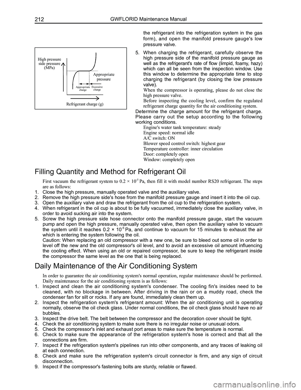
High pressure side pressure(MPa)
Appropriate pressure
Appropriate chargeExcessive charge
Refrigerant charge (g)
5. When charging the refrigerant, carefully observe the
high pressure side of the manifold pressure gauge as
well as the refrigerant's rate of flow (limpid, foamy, hazy)
which can all be seen from the inspection window. Use
this window to determine the appropriate time to stop
charging the refrigerant (by closing the low pressure
valve).
When the compressor is operating, please do not close the
high pressure valve.
Before inspecting the cooling level, confirm the regulated
refrigerant charge quantity for the air conditioning system.
Determine the charge amount for the refrigerant charge.
Please carry out the setup according to the following
working conditions.
Engine's water tank temperature: steady
Engine speed: normal idle
A/C switch: ON
Blower speed control switch: highest gear
Temperature controller: inner circulation
Door: completely open
Window: completely open
Filling Quantity and Method for Refrigerant Oil
First vacuum the refrigerant system to 0.2 × 10⁻⁵ Pa, then fill it with model number RS20 refrigerant. The steps
are as follows:
1. Close the high pressure, manually operated valve and the auxiliary valve\
.
2. Remove the high pressure side's hose from the manifold pressure gauge an\
d insert it into the oil cup.
3. Open the auxiliary valve and draw the refrigerant from the oil cup to th\
e refrigeration system.
4. When refrigerant in the oil cup is about to be fully vacuumed, immediately close the auxiliary valve, in
order to avoid sucking air into the system.
5. Screw the high pressure side hose connector onto the manifold pressure gauge, start the vacuum
pump and open the high pressure, manually operated valve, then open the auxiliary valve to vacuum
the system until it reaches 0.2 × 10⁻⁵ Pa, and continue to vacuum for 15 minutes to exhaust the air
which is entering the system following the oil.
Caution: When replacing an old compressor with a new one, be sure to bleed out some oil in order to
level off the new and the old compressor's oil level, and to avoid an excessive oil amount influencing
the cooling effect. When using an old or repaired compressor, be sure to keep the refrigerant inside
the compressor the same level as the one that is being replaced.
Daily Maintenance of the Air Conditioning System
In order to guarantee the air conditioning system's normal operation, regular maintenance should be performed.
Daily maintenance for the air conditioning system is as follows:
1. Inspect and clean the air conditioning system's condenser. The cooling fin's insides need to be
cleaned, with no blockage in between. After driving in the rain or on a muddy road, check the
condenser fan for silt or rocks. If any are found, immediately clean the\
m up.
2. Inspect the refrigeration system's refrigerant amount: When the air conditioning unit is operating
normally, observe the oil check glass. Under normal conditions, the oil check glass should have no air
bubbles.
3. Inspect the drive belt. The belt between the compressor and the decoration cover should be tight\
.
4. Check the air conditioning system to make sure there is no irregular noi\
se or unusual odors.
5. Check the compressor's inlet and exhaust port areas to make sure the tem\
perature is normal.
6. Check to make sure the appearance of the refrigeration system's hose is correct and that all the
connections are firm.
7. Inspect if the refrigeration system's pipelines run into other components, and any traces of leaking oil
at each connection.
8. Check and make sure the refrigeration system's circuit connector is firm, and any sign of circuit
disconnection.
9. Inspect if the compressor's fastening bolts are sturdy, reliable or flawed.
the refrigerant into the refrigeration system in the gas
form), and open the manifold pressure gauge's low
pressure valve.
Page 234 of 281
Downloaded from www.Manualslib.com manuals search engine 227Airbags
Removal Method for Individual Components
SRS airbag system electronic control component (SRS-ECU)
1. Areas of Importance
(a) After taking off the battery's negative (-) terminal, wait for 60 s before operating. Wrap the removed
negative (-) terminal in tape to insulate it.
(b) The SRS-ECU can not be dismantled or repaired. If there is any malfunction, please replace it with a new
one.
(c) Do not let the SRS-ECU vibrate or collide with anything. If sunken or depressed, cracked, deformed, etc.,
please replace with a new SRS-ECU.
(d) Every time the airbag is deployed, please replace with a new SRS-ECU.
(e) Do not knock the SRS-ECU while removing or performing maintenance on the SRS-ECU's surrounding
components.
2. Operation before removal
(a) Set the ignition switch to the LOCK position.
(b) After taking off the battery's negative (-) terminal, put them in a proper place or wrap them in\
tape.
3. Removal sequence
(a) Remove the auxiliary facia console.
(b) Reomve the connectors connected with the airbag ECU.
(c) Remove the SRS-ECU.
4. Installation sequence
(a) SRS-ECU.
(b) Install the connectors connected with the airbag ECU.
(c) Dashboard base.
(d) Connect the battery's negative (-) terminal.
5. Installation points
(a) Install the SRS-ECU
Caution: If SRS-ECU isn't installed correctly, the SRS airbag will not operate properly.
(b) Inspection after installation
• Set the ignition switch to the ON position.
• SRS warning lamp stays on for 6-7 s.
• If the lamp does not turn off, malfunction inspection and troubleshooting should be performed.
6. Inspection
(a) Whether the SRS-ECU cover has sunken or depressed, cracked, deformed, etc.
(b) Whether the connectors are damaged or deformed.
Caution: Please replace with a new SRS-ECU, if there is any sunkeness or depression, cracking, de-
formity, etc.
Except for the areas described above, to perform SRS-ECU inspections, please refer to the related troubleshooting
contents.
Page 236 of 281
Downloaded from www.Manualslib.com manuals search engine 229Airbags
3. Driver side airbag module installation sequence (after steering wheel i\
nstallation is completed)
(a) Install the horn's wire harness.
(b) Install the airbag module executing equipment's (gas generator) wire harness.
(c) Place the airbag module onto the steering wheel's proper installation position (avoid heavy knocking while
placing).
(d) Tighten the airbag module mounting bolt.
(e) Connect the battery's negative (-) terminal.
(f) Inspection after installation.
Auxiliary airbag removal and installation
1. Auxiliary airbag removal
(a) Remove the glove box.
(b) Pull out the dashboard wire harness and the auxiliary airbag wire harness connectors.
(c) Remove the airbag mounting bolt.
(d) Remove the upper dashboard.
(e) Remove the auxiliary airbag's two mounting nuts.
(f) Press the buckle and remove the auxiliary airbag.
2. Installation sequence for the auxiliary airbag is reverse to the removal\
sequence.
Caution: Please do not place anything on the auxiliary airbag, as to avoid accidents while deploying
the airbag.
Operation essentials
1. Driver side airbag and steering wheel removal
Caution: The following operations should only be performed after the battery's negative (-) terminal
has been disconnected, and after the ignition switch key has been pulled\
out for 60 s.
(a) Remove the mounting screws from the two holes under the steering wheel bottom cap, and lightly pick up
the driver side airbag module.
(b) Pull out the deployed airbag module's wire harness and the horn line, and remove the airbag module\
.
Attention: Diagnose the airbag module's circuit with an electrical measuring instruments but do not
dismantle it. Face the bottom of the removed passenger side airbag upwards and store it in a clean
and dry place.
(c) Remove the steering wheel mounting bolt on the steering column.
Caution: Due to the over-tight occlusion of the spline and column, the steering wheel and steering
column may be hard to separate, in which case make sure not to use force to remove the steering
wheel. The correct method is to tighten the screw into the column just a bit, and then pull up the
steering wheel (because the steering wheel bottom is connected to the clock spring, if force is used to
remove it, it may damage it).
2. Clock spring removal
(a) After steering wheel removal is completed, remove the combination switch hood.
(b) Pull out the dashboard wire harness connectors under the clock spring.
(c) Take off the clock spring.
Caution: Store the removed clock spring in a clean and dry place.
3. Installation notes
(a) Inspection before installation, inspection of driver side airbag module.
(b) Inspect the new airbag or clock spring before installing them.
4. Driver side airbag module inspection
Inspect each of the following items. If any faults are found, replace with a new corresponding airbag module
part. Discard the old components after they have been deployed in the pr\
oper order.
(a) Whether the cover sunken or depressed, cracked, or deformed.
(b) Whether the wire harness has broken connectors and deformed terminals.
(c) Whether the gas generator's housing is sunken or depressed, cracked, or deformed.
(d) Airbag module installation status.
Caution: The specified measuring instrument cannot measure the airbag module (tube rupture) circuit
resistance. Test the resistance with a testing instrument. There is an electric current in the tube rup-
ture which may lead to accidental deployment due to static electricity a\
nd cause serious accidents.
5. Clock spring inspection
Inspect each of the following items. If any fault is found, replace with\
a new clock spring.