fuel filter GREAT WALL FLORID 2008 Service Manual
[x] Cancel search | Manufacturer: GREAT WALL, Model Year: 2008, Model line: FLORID, Model: GREAT WALL FLORID 2008Pages: 281, PDF Size: 43.97 MB
Page 4 of 281
Downloaded from www.Manualslib.com manuals search engine Chapter One: Overview ........................................................................\
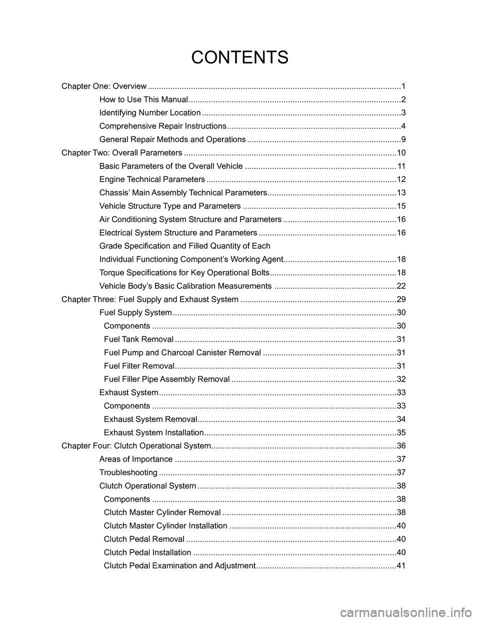
........................................1
How to Use This Manual ...................................................................................\
...........2
Identifying Number Location ..................................................................................\
......3
Comprehensive Repair Instructions .............................................................................4
General Repair Methods and Operations ....................................................................9
Chapter Two: Overall Parameters ........................................................................\
......................10
Basic Parameters of the Overall Vehicle ...................................................................11
Engine Technical Parameters ..................................................................................\
..12
Chassis’ Main Assembly Technical Parameters .........................................................13
Vehicle Structure Type and Parameters ....................................................................15
Air Conditioning System Structure and Parameters ..................................................16
Electrical System Structure and Parameters .............................................................16
Grade Specification and Filled Quantity of Each
Individual Functioning Component’s Working Agent ..................................................18
Torque Specifications for Key Operational Bolts ........................................................18
Vehicle Body’s Basic Calibration Measurements ......................................................22
Chapter Three: Fuel Supply and Exhaust System .....................................................................29
Fuel Supply System ...................................................................................\
................30
Components ..................................................................................\
..........................30
Fuel Tank Removal ..................................................................................\
................31
Fuel Pump and Charcoal Canister Removal ...........................................................31
Fuel Filter Removal ...................................................................................\
...............31
Fuel Filler Pipe Assembly Removal .........................................................................32
Exhaust System ...................................................................................\
......................33
Components ..................................................................................\
..........................33
Exhaust System Removal ...................................................................................\
.....34
Exhaust System Installation ...................................................................................\
..35
Chapter Four: Clutch Operational System........................................................................\
..........36
Areas of Importance ..................................................................................\
................37
Troubleshooting ..................................................................................\
.......................37
Clutch Operational System ..................................................................................\
......38
Components ..................................................................................\
..........................38
Clutch Master Cylinder Removal .............................................................................38
Clutch Master Cylinder Installation ..........................................................................40
Clutch Pedal Removal ..................................................................................\
...........40
Clutch Pedal Installation ..................................................................................\
........40
Clutch Pedal Examination and Adjustment ..............................................................41
CONTENTS
Page 20 of 281
Downloaded from www.Manualslib.com manuals search engine 13Overall Parameters
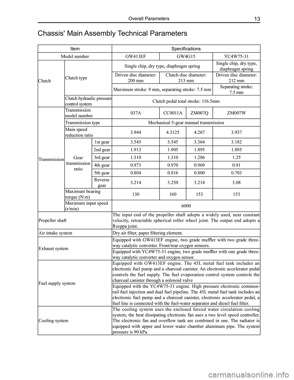
Chassis' Main Assembly Technical Parameters
ItemSpecifications
Model numberGW413EFGW4G15YC4W75-31
ClutchClutch type
Single chip, dry type, diaphragm springSingle chip, dry type,
diaphragm spring
Driven disc diameter:
200 mm
Clutch disc diameter:
213 mm
Driven disc diameter:
212 mm
Maximum stroke: 9 mm, separating stroke: 7.5 mmSeparating stroke:
7.5 mm
Clutch hydraulic pressure
control systemClutch pedal total stroke: 116.5mm
Transmission
Transmission
model number037ACC0011AZM007QZM007W
Transmission typeMechanical 5-gear manual transmission
Main speed
reduction ratio3.9444.31254.2673.937
Gear
transmission
ratio
1st gear3.5453.5453.3643.182
2nd gear1.9131.9051.8951.895
3rd gear1.3101.3101.2861.25
4th gear0.9730.9700.9690.91
5th gear0.8040.8160.8000.703
Reverse
gear3.2143.2503.2143.08
Maximum bearing
torque (N·m)130160153153
Maximum input speed
(r/min)6000
Propeller shaft
The input end of the propeller shaft adopts a widely used, near constant
velocity, retractable spherical roller wheel joint. The output end adopts a
Rzeppa joint.
Air intake systemDry air filter, paper filtering element.
Exhaust system
Equipped with GW413EF engine, two grade muffler with two grade three-
way catalytic converter. Front/rear oxygen sensors.
Equipped with YC4W75-31 engine, two grade muffler with one grade three-
way catalytic converter and oxygen sensor.
Fuel supply system
Equipped with GW413EF engine. The 45L metal fuel tank includes an
electronic fuel pump and a charcoal canister. An electronic accelerator pedal
controls the fuel supply. The fuel evaporation control system controls the
charcoal canister through a solenoid valve
Equipped with the YC4W75-31 engine. High pressure electronic common-
rail fuel injection and dual fuel pipeline. The 45L metal fuel tank includes an
electronic fuel pump and a charcoal canister, electronic accelerator pedal, a
fuel line is connected with the fuel-water separator and diesel fuel filter.
Cooling system
The cooling system uses the enclosed forced water circulation cooling
system, the heat dissipating electronic fan uses a two level speed controller.
The electronic fan and overflow tank are combined in one. The radiator is
equipped with upper and lower water chamber aluminum pipe. The system
pressure is 90 kPa.
Page 26 of 281
Downloaded from www.Manualslib.com manuals search engine 19Overall Parameters
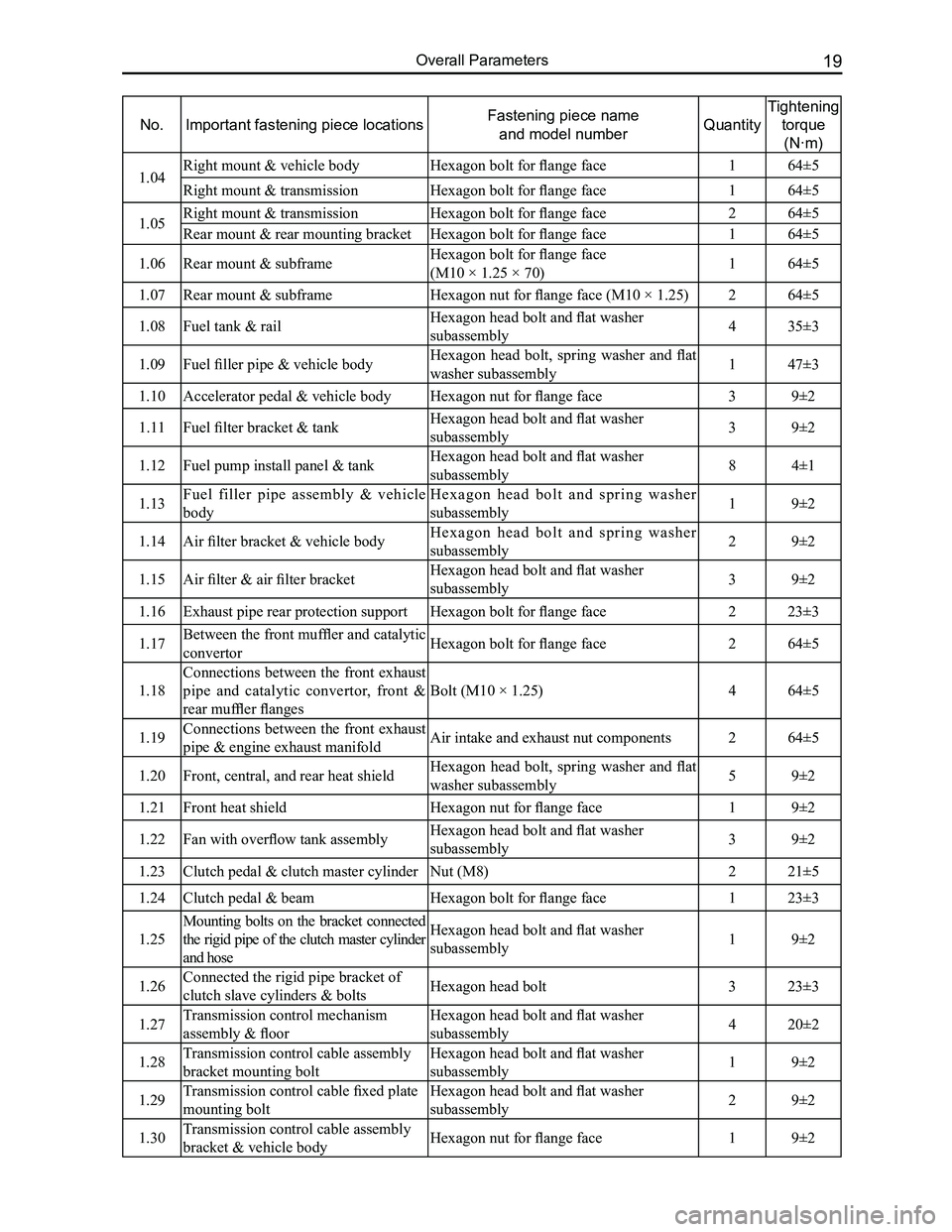
No.Important fastening piece locationsFastening piece name
and model numberQuantity
Tightening
torque
(N·m)
1.04Right mount & vehicle bodyHexagon bolt for flange face164±5
Right mount & transmissionHexagon bolt for flange face 164±5
1.05Right mount & transmissionHexagon bolt for flange face 264±5
Rear mount & rear mounting bracketHexagon bolt for flange face 164±5
1.06Rear mount & subframeHexagon bolt for flange face
(M10 × 1.25 × 70)164±5
1.07Rear mount & subframeHexagon nut for flange face (M10 × 1.25)264±5
1.08Fuel tank & railHexagon head bolt and flat washer
subassembly435±3
1.09Fuel filler pipe & vehicle bodyHexagon head bolt, spring washer and flat
washer subassembly147±3
1.10Accelerator pedal & vehicle bodyHexagon nut for flange face39±2
1.11Fuel filter bracket & tankHexagon head bolt and flat washer
subassembly39±2
1.12Fuel pump install panel & tankHexagon head bolt and flat washer
subassembly84±1
1.13Fuel filler pipe assembly & vehicle
body
H e x a g o n h e a d b o l t a n d s p r i n g w a s h e r
subassembly19±2
1.14Air filter bracket & vehicle bodyH e x a g o n h e a d b o l t a n d s p r i n g w a s h e r
subassembly29±2
1.15Air filter & air filter bracketHexagon head bolt and flat washer
subassembly39±2
1.16Exhaust pipe rear protection supportHexagon bolt for flange face223±3
1.17Between the front muffler and catalytic
convertorHexagon bolt for flange face264±5
1.18
Connections between the front exhaust
pipe and catalytic convertor, front &
rear muffler flanges
Bolt (M10 × 1.25)464±5
1.19Connections between the front exhaust
pipe & engine exhaust manifoldAir intake and exhaust nut components264±5
1.20Front, central, and rear heat shieldHexagon head bolt, spring washer and flat
washer subassembly59±2
1.21Front heat shieldHexagon nut for flange face19±2
1.22Fan with overflow tank assemblyHexagon head bolt and flat washer
subassembly39±2
1.23Clutch pedal & clutch master cylinderNut (M8)221±5
1.24Clutch pedal & beamHexagon bolt for flange face123±3
1.25
Mounting bolts on the bracket connected
the rigid pipe of the clutch master cylinder
and hose
Hexagon head bolt and flat washer
subassembly19±2
1.26Connected the rigid pipe bracket of
clutch slave cylinders & boltsHexagon head bolt323±3
1.27Transmission control mechanism
assembly & floor
Hexagon head bolt and flat washer
subassembly420±2
1.28Transmission control cable assembly
bracket mounting bolt
Hexagon head bolt and flat washer
subassembly19±2
1.29Transmission control cable fixed plate
mounting bolt
Hexagon head bolt and flat washer
subassembly29±2
1.30Transmission control cable assembly
bracket & vehicle bodyHexagon nut for flange face19±2
Page 36 of 281
Downloaded from www.Manualslib.com manuals search engine 29Fuel Supply and Exhaust System
Fuel Supply and Exhaust System
Fuel Supply System............................................................30
Components .....................................................................30
Fuel Tank Removal ...........................................................31
Fuel Pump and Charcoal Canister Removal ....................31
Fuel Filter Removal ..........................................................31
Fuel Filler Pipe Assembly Removal ..................................32
Exhaust System..................................................................33
Components .....................................................................33
Exhaust System Removal ................................................34
Exhaust System Installation .............................................35
Page 37 of 281
Downloaded from www.Manualslib.com manuals search engine 30GWFLORID Maintenance Manual
Fuel Supply System
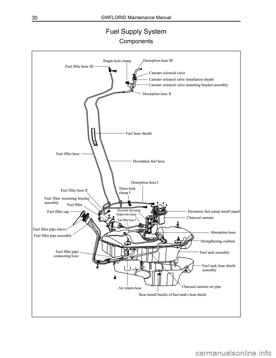
Components
Fuel filler hose III
Canister solenoid valve
Canister solenoid valve installation sheath
Canister solenoid valve mounting bracket assembly
Fuel hose sheath
Desorption fuel hose
Fuel filler hose
Desorption hose I
Fuel filler hose IIThree-hole clamp I
Charcoal canister
Fuel tank assembly
Fuel tank heat shield assembly
Charcoal canister air pipeAir return hose
Fuel filler pipe assembly
Electronic fuel pumpSingle-hole clampElectronic fuel pump install panel
Strengthening cushion
Fuel filler pipe connecting hose
Absorption hoseFuel filler pipe sleeve
Single-hole clamp
Fuel filter
Rear install buckle of fuel tank's heat shield
Fuel filler cap
Fuel filler hose I
Desorption hose III
Desorption hose II
Fuel filter mounting bracket assembly
Page 38 of 281
Downloaded from www.Manualslib.com manuals search engine 31Fuel Supply and Exhaust System
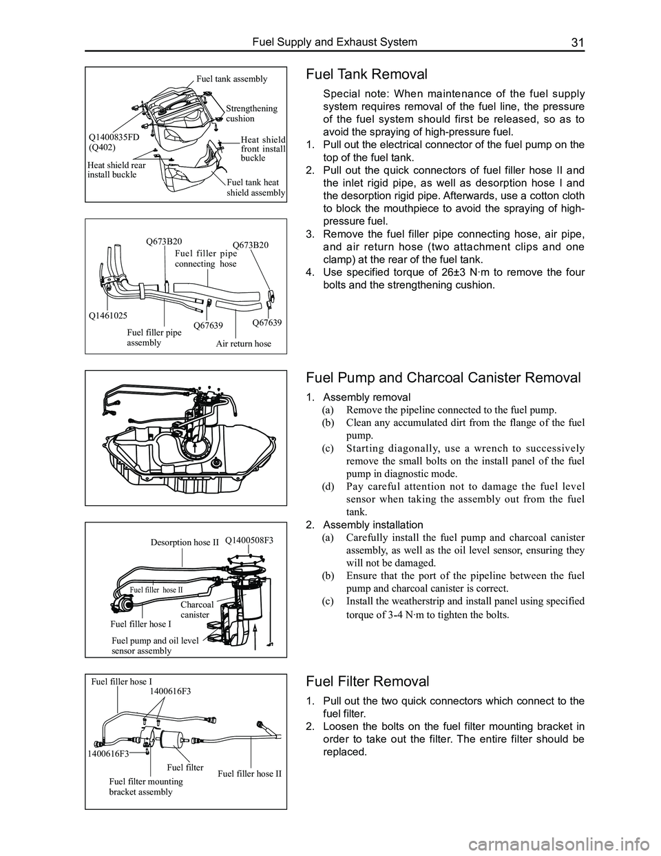
Fuel Tank Removal
Special note: When maintenance of the fuel supply
system requires removal of the fuel line, the pressure
of the fuel system should first be released, so as to
avoid the spraying of high-pressure fuel.
1. Pull out the electrical connector of the fuel pump on the
top of the fuel tank.
2. Pull out the quick connectors of fuel filler hose II and
the inlet rigid pipe, as well as desorption hose I and
the desorption rigid pipe. Afterwards, use a cotton cloth
to block the mouthpiece to avoid the spraying of high-
pressure fuel.
3. Remove the fuel filler pipe connecting hose, air pipe,
and air return hose (two attachment clips and one
clamp) at the rear of the fuel tank.
4. Use specified torque of 26±3 N·m to remove the four
bolts and the strengthening cushion.
Fuel Pump and Charcoal Canister Removal
1. Assembly removal
(a) Remove the pipeline connected to the fuel pump.
(b) Clean any accumulated dirt from the flange of the fuel
pump.
(c) Starting diagonally, use a wrench to successively
remove the small bolts on the install panel of the fuel
pump in diagnostic mode.
(d) Pay careful attention not to damage the fuel level
sensor when taking the assembly out from the fuel
tank.
2. Assembly installation
(a) Carefully install the fuel pump and charcoal canister
assembly, as well as the oil level sensor, ensuring they
will not be damaged.
(b) Ensure that the port of the pipeline between the fuel
pump and charcoal canister is correct.
(c) Install the weatherstrip and install panel using specified
torque of 3-4 N·m to tighten the bolts.
Fuel Filter Removal
1. Pull out the two quick connectors which connect to the
fuel filter.
2. Loosen the bolts on the fuel filter mounting bracket in
order to take out the filter. The entire filter should be
replaced.
Air return hose
Fuel filler pipe connecting hose
Fuel filler pipe assembly
Q1461025Q67639
Q673B20
Q67639
Q673B20
Fuel filler hose I1400616F3
Fuel filter mounting bracket assembly
Fuel filterFuel filler hose II
1400616F3
Desorption hose II
Fuel filler hose II
Fuel filler hose I
Charcoalcanister
Fuel pump and oil level sensor assembly
Q1400508F3
Strengthening cushion
Heat shield front install buckle
Fuel tank heat shield assembly
Heat shield rear install buckle
Fuel tank assembly
Q1400835FD(Q402)