light GREAT WALL FLORID 2008 Service Manual
[x] Cancel search | Manufacturer: GREAT WALL, Model Year: 2008, Model line: FLORID, Model: GREAT WALL FLORID 2008Pages: 281, PDF Size: 43.97 MB
Page 2 of 281
Downloaded from www.Manualslib.com manuals search engine PREFACE
GWFLORID will build 1.3L (GW413EF, GW4G13) or 1.5L (GW4G15) gasoline engines, in which the
GW4G13 and GW4G15 engines will both incorporate the newest VVT technology which meets the Euro IV
emission standards. GWFLORID features McPherson technology on its chassis system. With an ultra light
body made from structural steel and high-intensity front and rear fender impact beams as well as a collision
impact absorption system, it is able to maintain the cab's integrity and safety to greater extent. We wrote this
maintenance manual in order to meet the demand of Great Wall after-sales service technicians. This manual
mainly introduces the areas of importance in regard to maintenance and care, and removal and installation of
each system's assembly and maintenance technical parameters.
To reduce the possibility of injury or property damage, read and follow t\
he instructions carefully:
This manual is provided by the Great Wall Motor Co., Ltd, and is written for the technician use. Any
maintenance or repair without proper prior training and tools or devices may result in personal injury of the
person performing the maintenance or others in the vicinity. It is also possible that damage to the vehicle will
occur or will lead to mechanical failure during normal operation.
Correct vehicle maintenance and repair is essential for the safety of the person performing regular
maintenance as well as the vehicle itself. If there is any component that needs to be replaced, use a
component with the same serial number or a serial number specified by the Great Wall Motor Co., Ltd. Never
use any part that has not been authorized by the Great Wall Motor Co., Ltd.
Any maintenance procedure introduced in this manual is effective for maintenance and repair. Some of
these procedures need specially designed tools.
Therefore, before using any vehicle part following any maintenance procedure or working with a tool
that has not been authorized by the Great Wall Motor Co., Ltd, check to make sure that none of the above
will endanger the safety of the person performing the work or the correc\
t operation of the vehicle.
This manual includes multiple "Warnings" and "Cautions," which should be strictly followed, so as to
reduce the possibility of injury during maintenance or repair. Improper maintenance or repair of the vehicle
may cause potential safety hazards. These "Warnings" and "Cautions" are not exhaustive. It is impossible for
the Great Wall Motor Co., Ltd, to warn against all the potential dangers caused by not properly following the
instructions.
Please read carefully the "Areas of Importance" before carrying out any maintenance or repair on the
airbag system's components or its surrounding electrical components. Action contrary to any of the "Areas of
Importance" may lead to the deployment of the airbag, resulting in injur\
y or unnecessary repair of the airbag.
To avoid accidental deployment of the airbag and its resulting injury, we suggest repairing the airbag
system before other vehicle systems if the airbag and the other vehicle \
systems both need repairing.
We have received generous support and help from many professional technicians during the preparation
of this manual. We would like to express our heartfelt gratitude to all of them.
Although we have tried our best to write this manual well, we do not guarantee that the entire content
in this manual is absolutely correct. Users may not make any legal claim against the Great Wall Motor Co.,
Ltd. in regards to this manual. Any loss caused by using this manual is not our responsibility. Because of
the writer's limited experience, there are likely mistakes in this manual, therefore we welcome any user
comments, suggestions, and corrections.
Great Wall Motor Co., Ltd. reserves the final right of explanation.
\
Editor
May 2008
Page 9 of 281
Downloaded from www.Manualslib.com manuals search engine GWFLORID Maintenance Manual2
How to Use This Manual
1. There is a content index on the first page of each
chapter. You can consult the index to see the items
needed for maintenance. In order to make searching
more convenient, the subject of each chapter has been
printed on the page header of each odd page.
2. There is a summary or caution item in the beginning of
each chapter. Please read this content carefully before
any maintenance is performed. Some systems include
a malfunction diagnostic table to help determine ve-
hicle failures and their causes.
3. Throughout the entire manual, each maintenance
step's corresponding specification is highlighted in bold,
so there should be no need to pause maintenance
work in order to find these specifications.
4. Warnings, Cautions & Notes
• Warnings are highlighted in bold, indicating the possibility
of causing injury to oneself or to others.
• Cautions are highlighted in bold, indicating the possibility
of damaging the part being repaired.
• Notes are listed separately from the instructions, not high-
lighted in bold. They are mainly used for additional expla-
nations in order to work more effectively.
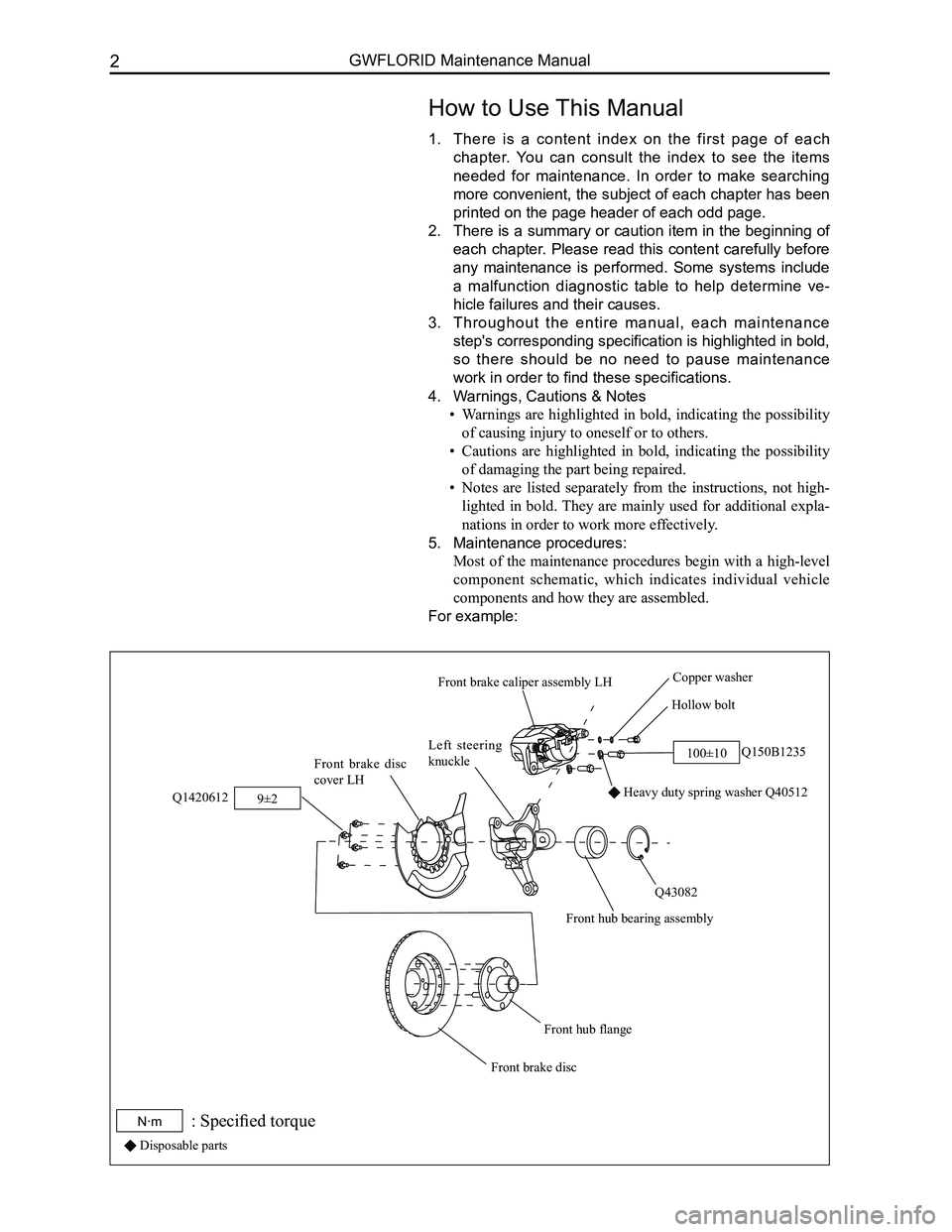
5. Maintenance procedures:
Most of the maintenance procedures begin with a high-level
component schematic, which indicates individual vehicle
components and how they are assembled.
For example:
Hollow bolt
Copper washer
Q150B1235
Heavy duty spring washer Q40512
Q43082
Front hub bearing assembly
Left steering
knuckleFront brake disc
cover LH
Q1420612
Front hub flange
Front brake disc
Front brake caliper assembly LH
100±10
9±2
N·m: Specified torque
Disposable parts
Page 13 of 281
Downloaded from www.Manualslib.com manuals search engine GWFLORID Maintenance Manual6
2. Inspection procedures for related fuses or fuses in re- Inspection procedures for related fuses or fuses in re-Inspection procedures for related fuses or fuses in re-
lay boxes. Inspect the battery for damage, the battery's
charging state, cleanness, and tightening with the
connectors.
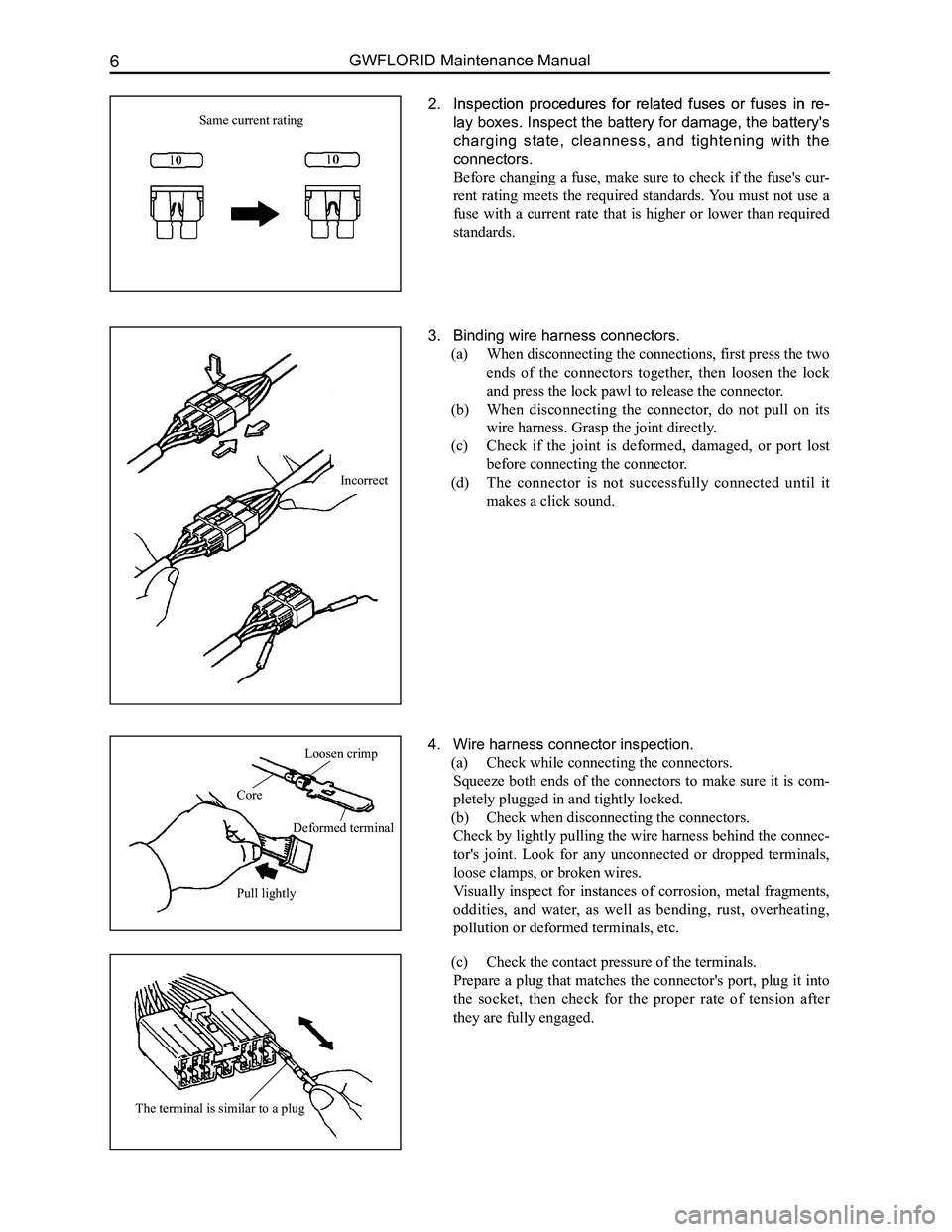
Before changing a fuse, make sure to check if the fuse's cur-
rent rating meets the required standards. You must not use a
fuse with a current rate that is higher or lower than required
standards.
Same current rating
3. Binding wire harness connectors.
(a) When disconnecting the connections, first press the two
ends of the connectors together, then loosen the lock
and press the lock pawl to release the connector.
(b) When disconnecting the connector, do not pull on its
wire harness. Grasp the joint directly.
(c) Check if the joint is deformed, damaged, or port lost
before connecting the connector.
(d) The connector is not successfully connected until it
makes a click sound.
4. Wire harness connector inspection.
(a) Check while connecting the connectors.
Squeeze both ends of the connectors to make sure it is com-
pletely plugged in and tightly locked.
(b) Check when disconnecting the connectors.
Check by lightly pulling the wire harness behind the connec-
tor's joint. Look for any unconnected or dropped terminals,
loose clamps, or broken wires.
Visually inspect for instances of corrosion, metal fragments,
oddities, and water, as well as bending, rust, overheating,
pollution or deformed terminals, etc.
(c) Check the contact pressure of the terminals.
Prepare a plug that matches the connector's port, plug it into
the socket, then check for the proper rate of tension after
they are fully engaged.
Loosen crimp
Core
Deformed terminal
Pull lightly
The terminal is similar to a plug
Incorrect
Page 23 of 281
Downloaded from www.Manualslib.com manuals search engine GWFLORID Maintenance Manual16
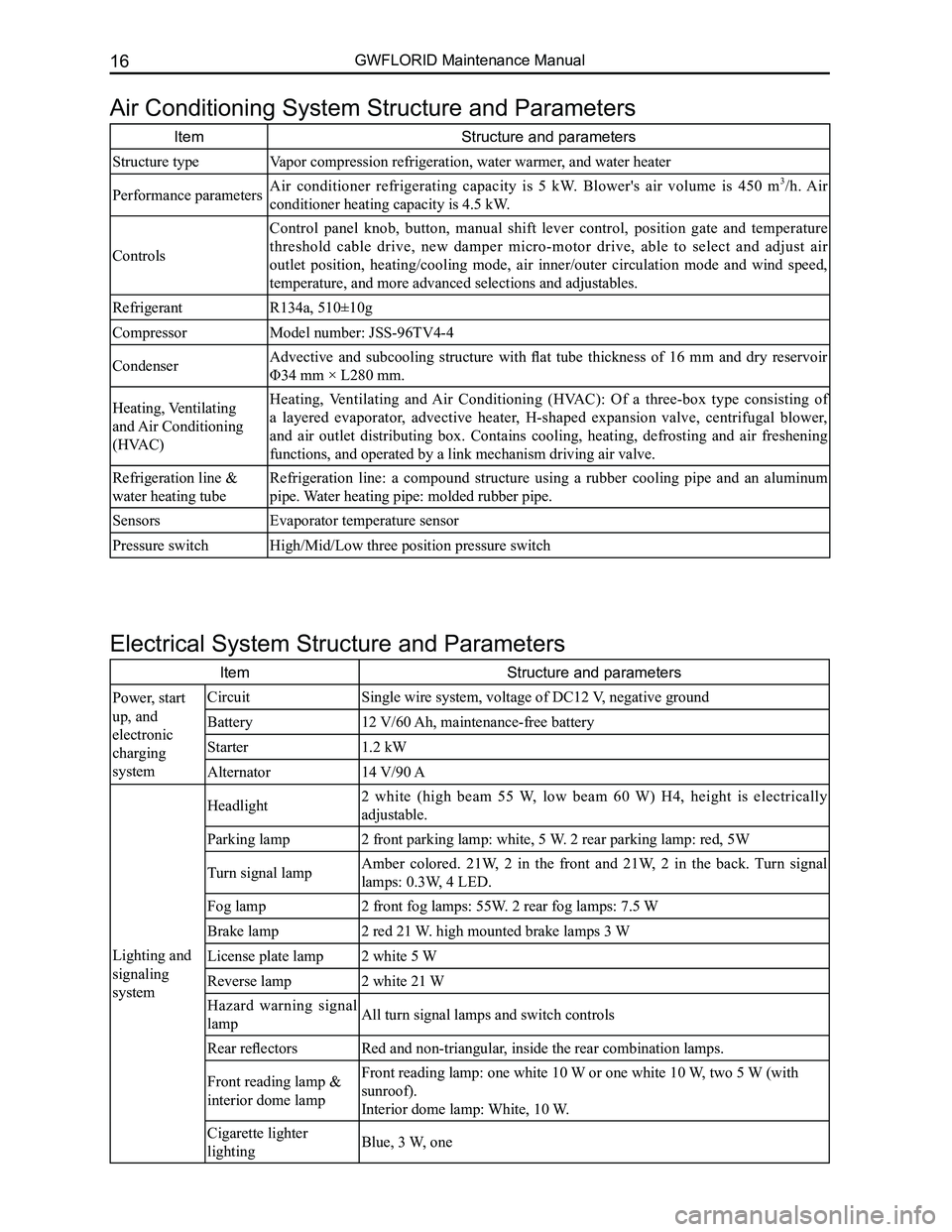
Air Conditioning System Structure and Parameters
ItemStructure and parameters
Structure typeVapor compression refrigeration, water warmer, and water heater
Performance parametersAir conditioner refrigerating capacity is 5 kW. Blower's air volume is 450 m3/h. Air
conditioner heating capacity is 4.5 kW.
Controls
Control panel knob, button, manual shift lever control, position gate and temperature
threshold cable drive, new damper micro-motor drive, able to select and adjust air
outlet position, heating/cooling mode, air inner/outer circulation mode and wind speed,
temperature, and more advanced selections and adjustables.
RefrigerantR134a, 510±10g
CompressorModel number: JSS-96TV4-4
CondenserAdvective and subcooling structure with flat tube thickness of 16 mm and dry reservoir
Φ34 mm × L280 mm.
Heating, Ventilating
and Air Conditioning
(HVAC)
Heating, Ventilating and Air Conditioning (HVAC): Of a three-box type consisting of
a layered evaporator, advective heater, H-shaped expansion valve, centrifugal blower,
and air outlet distributing box. Contains cooling, heating, defrosting and air freshening
functions, and operated by a link mechanism driving air valve.
Refrigeration line &
water heating tube
Refrigeration line: a compound structure using a rubber cooling pipe and an aluminum
pipe. Water heating pipe: molded rubber pipe.
SensorsEvaporator temperature sensor
Pressure switchHigh/Mid/Low three position pressure switch
Electrical System Structure and Parameters
ItemStructure and parameters
Power, start
up, and
electronic
charging
system
CircuitSingle wire system, voltage of DC12 V, negative ground
Battery12 V/60 Ah, maintenance-free battery
Starter1.2 kW
Alternator14 V/90 A
Lighting and
signaling
system
Headlight2 white (high beam 55 W, low beam 60 W) H4, height is electrically
adjustable.
Parking lamp2 front parking lamp: white, 5 W. 2 rear parking lamp: red, 5W
Turn signal lampAmber colored. 21W, 2 in the front and 21W, 2 in the back. Turn signal
lamps: 0.3W, 4 LED.
Fog lamp2 front fog lamps: 55W. 2 rear fog lamps: 7.5 W
Brake lamp2 red 21 W. high mounted brake lamps 3 W
License plate lamp2 white 5 W
Reverse lamp2 white 21 W
Hazard warning signal
lampAll turn signal lamps and switch controls
Rear reflectorsRed and non-triangular, inside the rear combination lamps.
Front reading lamp &
interior dome lamp
Front reading lamp: one white 10 W or one white 10 W, two 5 W (with
sunroof).
Interior dome lamp: White, 10 W.
Cigarette lighter
lightingBlue, 3 W, one
Page 24 of 281
Downloaded from www.Manualslib.com manuals search engine 17Overall Parameters
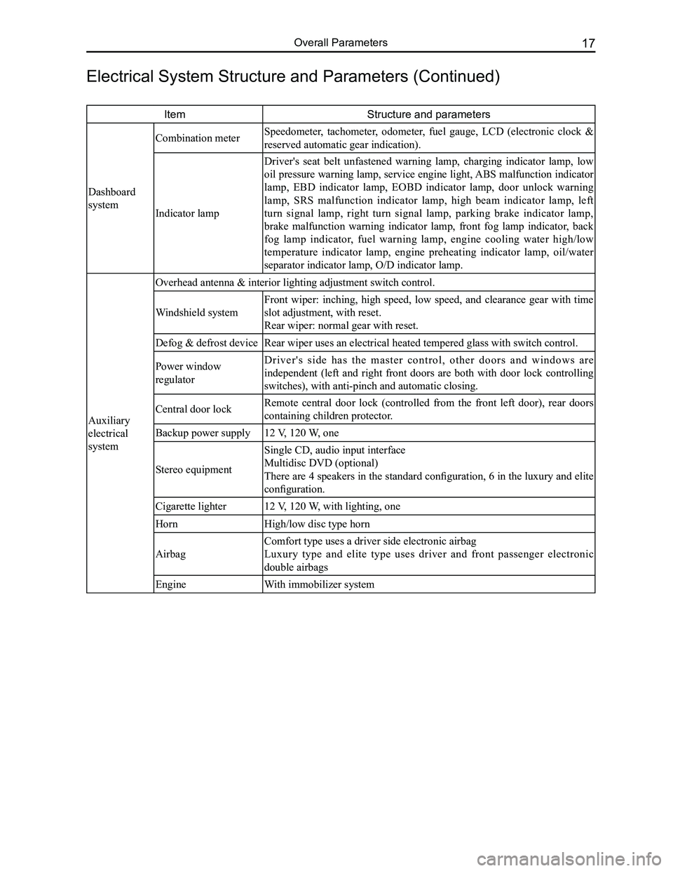
ItemStructure and parameters
Dashboard
system
Combination meter Speedometer, tachometer, odometer, fuel gauge, LCD (electronic clock &
reserved automatic gear indication).
Indicator lamp
Driver's seat belt unfastened warning lamp, charging indicator lamp, low
oil pressure warning lamp, service engine light, ABS malfunction indicator
lamp, EBD indicator lamp, EOBD indicator lamp, door unlock warning
lamp, SRS malfunction indicator lamp, high beam indicator lamp, left
turn signal lamp, right turn signal lamp, parking brake indicator lamp,
brake malfunction warning indicator lamp, front fog lamp indicator, back
fog lamp indicator, fuel warning lamp, engine cooling water high/low
temperature indicator lamp, engine preheating indicator lamp, oil/water
separator indicator lamp, O/D indicator lamp.
Auxiliary
electrical
system
Overhead antenna & interior lighting adjustment switch control.
Windshield system
Front wiper: inching, high speed, low speed, and clearance gear with time
slot adjustment, with reset.
Rear wiper: normal gear with reset.
Defog & defrost deviceRear wiper uses an electrical heated tempered glass with switch control.\
Power window
regulator
D r i v e r ' s s i d e h a s t h e m a s t e r c o n t r o l , o t h e r d o o r s a n d w i n d o w s a r e
independent (left and right front doors are both with door lock controlling
switches), with anti-pinch and automatic closing.
Central door lockRemote central door lock (controlled from the front left door), rear doors
containing children protector.
Backup power supply12 V, 120 W, one
Stereo equipment
Single CD, audio input interface
Multidisc DVD (optional)
There are 4 speakers in the standard configuration, 6 in the luxury and elite
configuration.
Cigarette lighter12 V, 120 W, with lighting, one
HornHigh/low disc type horn
Airbag
Comfort type uses a driver side electronic airbag
Luxury type and elite type uses driver and front passenger electronic
double airbags
EngineWith immobilizer system
Electrical System Structure and Parameters (Continued)
Page 25 of 281
Downloaded from www.Manualslib.com manuals search engine GWFLORID Maintenance Manual18
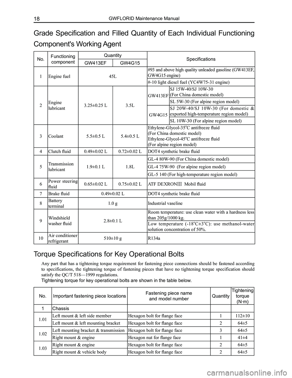
Torque Specifications for Key Operational Bolts
Any part that has a tightening torque requirement for fastening piece connections should be fastened according
to specifications, the tightening torque of fastening pieces that have no tightening torque specification should
satisfy the QC/T 518—1999 regulations.
Tightening torque for key operational bolts are shown in the table below.
No.Important fastening piece locationsFastening piece name
and model numberQuantity
Tightening
torque
(N·m)
1Chassis
1.01Left mount & left side memberHexagon bolt for flange face1112±10
Left mount & left mounting bracketHexagon bolt for flange face264±5
1.02Left mounting bracket & transmissionHexagon bolt for flange face364±5
Right mount & engineHexagon nut for flange face141±4
1.03Right mount & engineHexagon bolt for flange face264±5
Right mount & vehicle bodyHexagon bolt for flange face 264±5
Grade Specification and Filled Quantity of Each Individual Functioning
Component's Working Agent
No.Functioning
component
QuantitySpecificationsGW413EFGW4G15
1Engine fuel45L
#93 and above high quality unleaded gasoline (GW413EF,
GW4G15 engine)
#-10 light diesel fuel (YC4W75-31 engine)
2Engine
lubricant3.25±0.25 L3.5L
GW413EF
SJ 15W-40/SJ 10W-30
(For China domestic model)
SL 5W-30 (For alpine region model)
GW4G15
SJ 20W-40/SJ 10W-30 (For domestic &
exported high-temperature region model)
SL 10W-30 (For alpine region model)
3Coolant5.5±0.5 L5.4±0.5 L
Ethylene-Glycol-35oC antifreeze fluid
(For China domestic model)
Ethylene-Glycol-45oC antifreeze fluid
(For alpine region model)
4Clutch fluid0.49±0.02 L0.72±0.02 LDOT4 synthetic brake fluid
5Transmission
lubricant1.9±0.1 L1.8L
GL-4 80W-90 (For China domestic model)
GL-4 75W-90 (For alpine region model)
GL-5 140 (For high-temperature region model)
6Power steering
fluid0.65±0.02 L0.75±0.02 LATF DEXRONⅢ Mobil fluid
7Brake fluid0.49±0.02 LDOT4 synthetic brake fluid
8Battery
terminal1.0 gIndustrial vaseline
9Windshield
washer fluid2.8±0.1 L
Room temperature: use clean water with a hardness less
than 205g/1000 kg.
Low temperature (-18oC±3oC): use methanol-water
solution concentration of 50%.
10Air conditioner
refrigerant510±10 gR134a
Page 35 of 281
Downloaded from www.Manualslib.com manuals search engine GWFLORID Maintenance Manual28
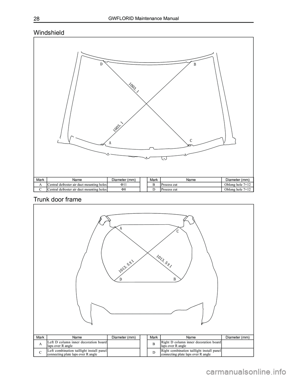
MarkNameDiameter (mm)MarkNameDiameter (mm)
ACentral defroster air duct mounting holesΦ11BProcess cutOblong hole 7×12
CCentral defroster air duct mounting holesΦ8DProcess cutOblong hole 7×12
MarkNameDiameter (mm)MarkNameDiameter (mm)
ALeft D column inner decoration board laps over R angleBRight D column inner decoration board laps over R angle
CLeft combination taillight install panel connecting plate laps over R angleDRight combination taillight install panel connecting plate laps over R angle
Trunk door frame
Windshield
Page 81 of 281
Downloaded from www.Manualslib.com manuals search engine GWFLORID Maintenance Manual74
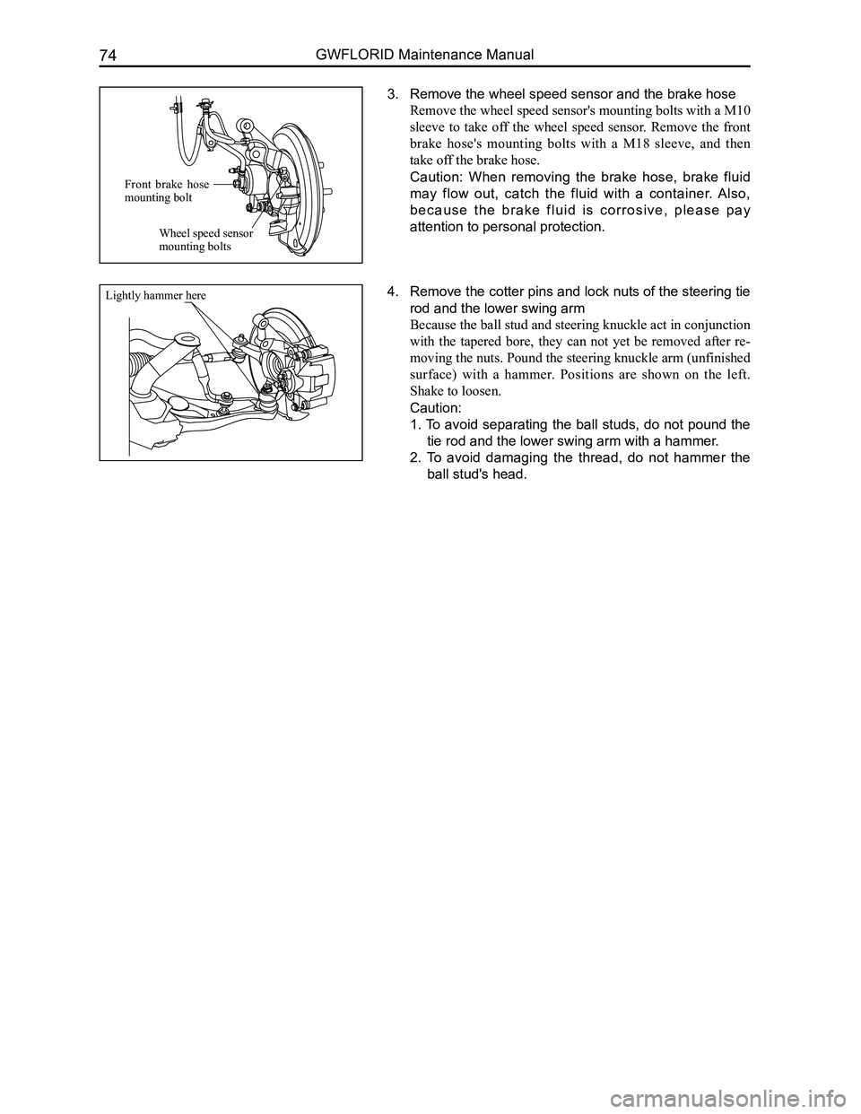
3. Remove the wheel speed sensor and the brake hose
Remove the wheel speed sensor's mounting bolts with a M10
sleeve to take off the wheel speed sensor. Remove the front
brake hose's mounting bolts with a M18 sleeve, and then
take off the brake hose.
Caution: When removing the brake hose, brake fluid
may flow out, catch the fluid with a container. Also,
b e c a u s e t h e b r a k e f l u i d i s c o r r o s i v e , p l e a s e p a y
attention to personal protection.
4. Remove the cotter pins and lock nuts of the steering tie
rod and the lower swing arm
Because the ball stud and steering knuckle act in conjunction
with the tapered bore, they can not yet be removed after re-
moving the nuts. Pound the steering knuckle arm (unfinished
surface) with a hammer. Positions are shown on the left.
Shake to loosen.
Caution:
1. To avoid separating the ball studs, do not pound the
tie rod and the lower swing arm with a hammer.
2. To avoid damaging the thread, do not hammer the
ball stud's head.
Front brake hose mounting bolt
Wheel speed sensor mounting bolts
Lightly hammer here
Page 85 of 281
Downloaded from www.Manualslib.com manuals search engine GWFLORID Maintenance Manual78
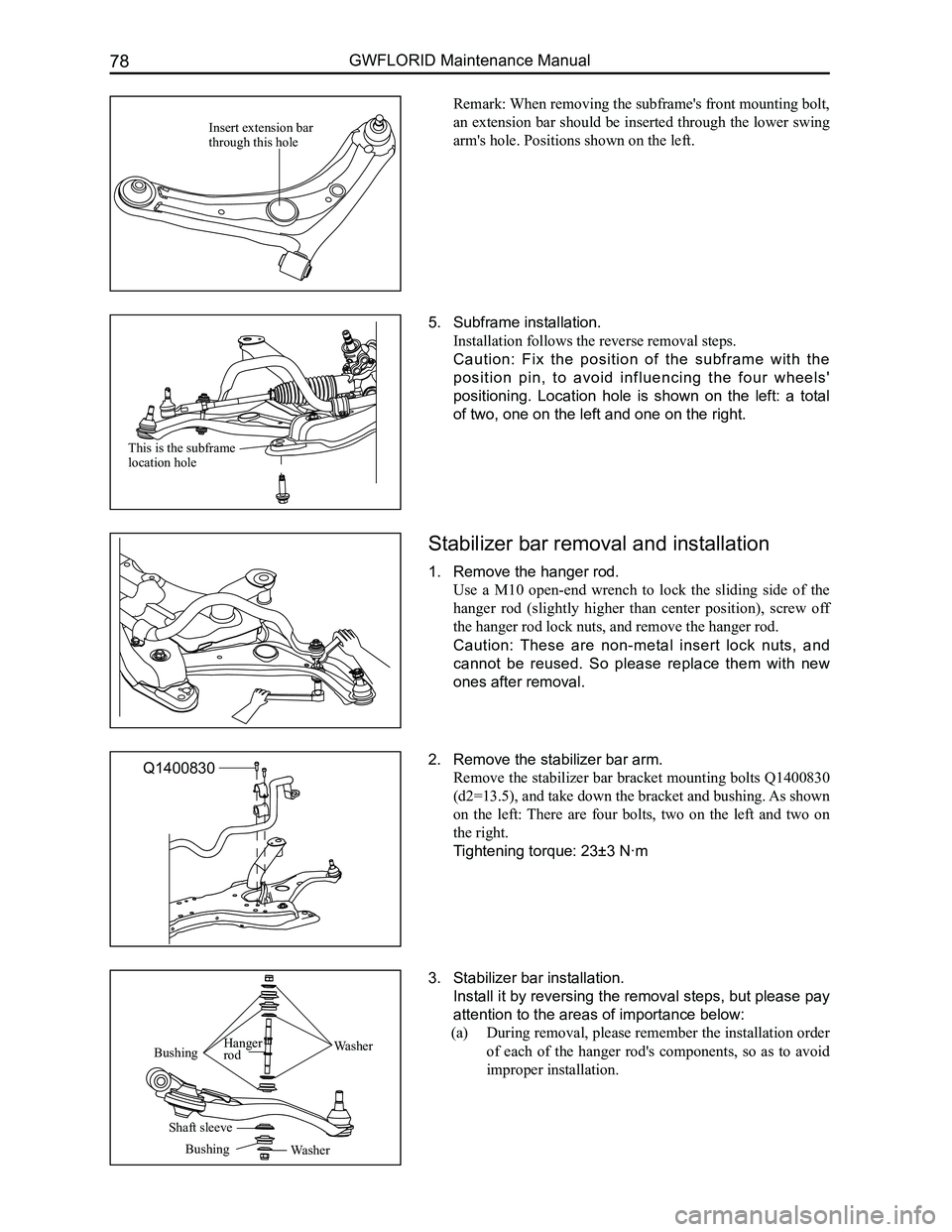
Remark: When removing the subframe's front mounting bolt,
an extension bar should be inserted through the lower swing
arm's hole. Positions shown on the left.
5. Subframe installation.
Installation follows the reverse removal steps.
Caution: Fix the position of the subframe with the
position pin, to avoid influencing the four wheels'
positioning. Location hole is shown on the left: a total
of two, one on the left and one on the right.
Stabilizer bar removal and installation
1. Remove the hanger rod.
Use a M10 open-end wrench to lock the sliding side of the
hanger rod (slightly higher than center position), screw off
the hanger rod lock nuts, and remove the hanger rod.
Caution: These are non-metal insert lock nuts, and
cannot be reused. So please replace them with new
ones after removal.
2. Remove the stabilizer bar arm.
Remove the stabilizer bar bracket mounting bolts Q1400830
(d2=13.5), and take down the bracket and bushing. As shown
on the left: There are four bolts, two on the left and two on
the right.
Tightening torque: 23±3 N·m
3. Stabilizer bar installation.
Install it by reversing the removal steps, but please pay
attention to the areas of importance below:
(a) During removal, please remember the installation order
of each of the hanger rod's components, so as to avoid
improper installation.
Insert extension bar through this hole
This is the subframe location hole
Q1400830
WasherBushingHanger rod
Shaft sleeve
BushingWasher
Page 99 of 281
Downloaded from www.Manualslib.com manuals search engine GWFLORID Maintenance Manual92
Wheel
General tire balancing procedures
Clean out the accumulated dirt and debris from the inside of the rim.
Warning:
The gravel on the tread must be eliminated to avoid flying out and injuring the operator when
undergoing rotational balancing. This is also a good way to acquire better balance. First thoroughly
inspect the tire's damaged condition, then according to the balancing device manufacture's
recommendations, carry out the balancing operation.
Off-vehicle balancing
Most off-vehicle balancers are more accurate and convenient than on-vehicle rotational balancers. They are
also able to perform dynamic (two sided) balancing. Although it does not correct drum brake and brake disc
imbalance like on-vehicle balancing, it achieves the same effect based on its accuracy.
On-vehicle balancing
On-vehicle balancing is different based on equipment and tool manufacturer. Therefore, when performing
balancing operations, be sure to comply to each manufacturer's operating\
instructions.
Warning: Control the wheel rotation speed to make sure the speedometer stays within 55 km/h.
This restriction is necessary because when a driven wheel slides while the other one stays still, the
speedometer will display only half of the actual wheel speed. When a wheel is sliding, be extremely
careful, because sliding wheels can reach very high speeds. This may lead to the tire rubber peeling
or differential damage, which may cause serious personal injury, or damage to the vehicle.
Tire installation and removal
• Install or remove tires with a tire changer. When operating machinery, make sure to comply to the machine
manufacturers operation manual. Please do not change tires merely with manual hand tools or tire installation
crowbars. This will damage the tire chafer or the vehicle wheel's rim.
• Use a wire brush or coarse steel wool to clean off grease and old rubber, as well as light rust or corrosion from
the rim tire bead's tire chafer seat. Before tire installation or removal, first use the indicated tire lubricant to
thoroughly lube the tire chafer portions one time.
• After installing the tire, inflate it to the specified pressure and make\
sure the tire bead is properly seated.
Warning: Do not over-inflate the tire. If the tire bead severally expands and exceeds the safety limit,
it may burst and cause serious personal injury. While inflating, do not exceed the specified pressure.
If the specified pressure does not allow the tire bead to sit properly, deflate the tire, re-lubricate, and
then re-inflate.
Spare tire usage
• Spare tire standard inflation pressure: 420 kPa.
• Spare tire pressure measurements should be taken under normal temperatur\
e conditions.
• After inflating the spare tire, soapy water should be used to check if the air nozzles core is leaking air, then
lock on the air nozzle cap.
• The spare tire should always be kept in a useable state. Check the air p\
ressure at least once a month.
• When the spare tire's working limit, indicated by the remaining pattern's depth, reaches 1.6 mm (and its pat-
tern groove bottom protrudes to the same level), for your safety, please stop using the spare tire.
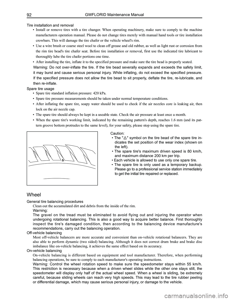
Caution:
• The "" symbol on the tire bead of the spare tire in-
dicates the set position of the wear index (shown on
the left).
• The spare tire's maximum driven speed is 80 km/h,
and maximum distance 200 km per trip.
• Each vehicle is allowed to use only one spare tire.
• The spare tire is only used as a temporary backup.
Please go to a professional service station immediately
to get the initial tire repaired or replaced.