horn GREAT WALL FLORID 2008 Service Manual
[x] Cancel search | Manufacturer: GREAT WALL, Model Year: 2008, Model line: FLORID, Model: GREAT WALL FLORID 2008Pages: 281, PDF Size: 43.97 MB
Page 24 of 281
Downloaded from www.Manualslib.com manuals search engine 17Overall Parameters
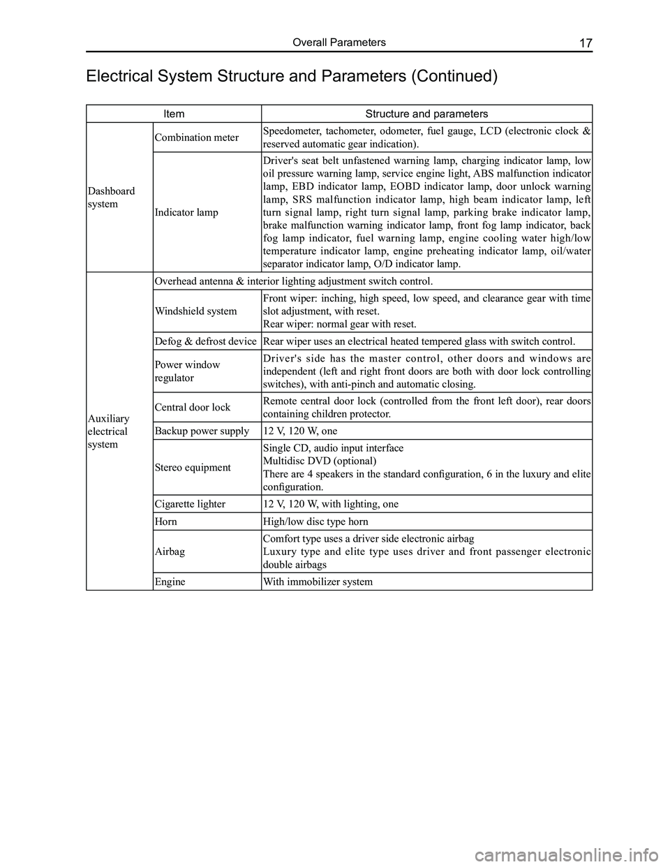
ItemStructure and parameters
Dashboard
system
Combination meter Speedometer, tachometer, odometer, fuel gauge, LCD (electronic clock &
reserved automatic gear indication).
Indicator lamp
Driver's seat belt unfastened warning lamp, charging indicator lamp, low
oil pressure warning lamp, service engine light, ABS malfunction indicator
lamp, EBD indicator lamp, EOBD indicator lamp, door unlock warning
lamp, SRS malfunction indicator lamp, high beam indicator lamp, left
turn signal lamp, right turn signal lamp, parking brake indicator lamp,
brake malfunction warning indicator lamp, front fog lamp indicator, back
fog lamp indicator, fuel warning lamp, engine cooling water high/low
temperature indicator lamp, engine preheating indicator lamp, oil/water
separator indicator lamp, O/D indicator lamp.
Auxiliary
electrical
system
Overhead antenna & interior lighting adjustment switch control.
Windshield system
Front wiper: inching, high speed, low speed, and clearance gear with time
slot adjustment, with reset.
Rear wiper: normal gear with reset.
Defog & defrost deviceRear wiper uses an electrical heated tempered glass with switch control.\
Power window
regulator
D r i v e r ' s s i d e h a s t h e m a s t e r c o n t r o l , o t h e r d o o r s a n d w i n d o w s a r e
independent (left and right front doors are both with door lock controlling
switches), with anti-pinch and automatic closing.
Central door lockRemote central door lock (controlled from the front left door), rear doors
containing children protector.
Backup power supply12 V, 120 W, one
Stereo equipment
Single CD, audio input interface
Multidisc DVD (optional)
There are 4 speakers in the standard configuration, 6 in the luxury and elite
configuration.
Cigarette lighter12 V, 120 W, with lighting, one
HornHigh/low disc type horn
Airbag
Comfort type uses a driver side electronic airbag
Luxury type and elite type uses driver and front passenger electronic
double airbags
EngineWith immobilizer system
Electrical System Structure and Parameters (Continued)
Page 153 of 281
Downloaded from www.Manualslib.com manuals search engine GWFLORID Maintenance Manual146
Main relay
10A backup 15A backup 25A backup
Compressor relay
Reserve
Reserve
Fuel pump
Starter relay Main
relay High
beam Low
beam
Engine ECU
Fan relay High
Starter relay High beam relay Low beam relay Reserve
Horn Reserve Reserve Fan relay Low
Fan relay Low
Fan relay High
Horn relay
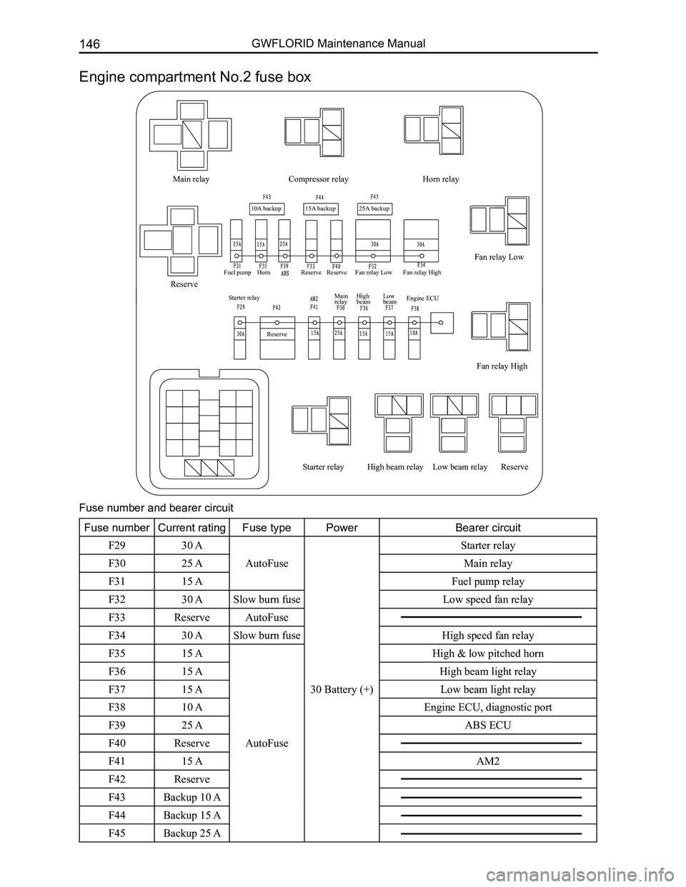
Engine compartment No.2 fuse box
Fuse number and bearer circuit
Fuse numberCurrent ratingFuse typePowerBearer circuit
F2930 A
AutoFuse
30 Battery (+)
Starter relay
F3025 AMain relay
F3115 AFuel pump relay
F3230 ASlow burn fuse Low speed fan relay
F33ReserveAutoFuse
F3430 ASlow burn fuse High speed fan relay
F3515 A
AutoFuse
High & low pitched horn
F3615 AHigh beam light relay
F3715 ALow beam light relay
F3810 AEngine ECU, diagnostic port
F3925 AABS ECU
F40Reserve
F4115 AAM2
F42Reserve
F43Backup 10 A
F44Backup 15 A
F45Backup 25 A
Page 159 of 281
Downloaded from www.Manualslib.com manuals search engine GWFLORID Maintenance Manual152
Engine ECUInjector
Starter, starter excitation, knock sensor
Speed sensor
Brake switch
Brake fluid level switch
Clutch switch
ABS ECU
Front wiper
motor
Front combination lamp LH
Front fog lamp LH
Radiator fan
High & low pitched horn
Crankshaft position sensorFront & rear oxygen sensor
Condenser fan motor
Compressor clutch
Alternator, alternator regulator
Tristate pressure switch
Front fog lamp RH
Washer motor
Wheel speed sensor
Front combination lamp RH
Camshaft position sensor
Throttle position sensor
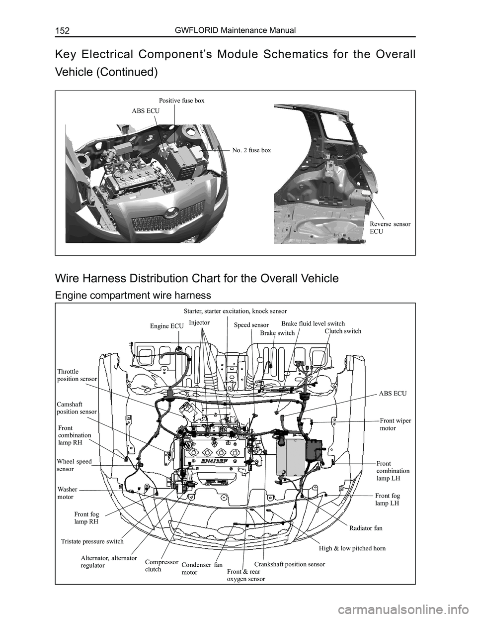
Wire Harness Distribution Chart for the Overall Vehicle
Engine compartment wire harness
ABS ECU
Positive fuse box
No. 2 fuse box
Reverse sensor ECU
Key Electrical Component’s Module Schematics for the Overall
Vehicle (Continued)
Page 162 of 281
Downloaded from www.Manualslib.com manuals search engine 155Vehicle Body Electronic System
Condenser fan motor
Connected compressor
Oil pressure switch
Front oxygen sensor
Connected reverse switch
Connected engine speed sensor Connected
ignition coil
Connected speed sensor Connected coolant temp. sensor
Canister control valve
Connected combination meter A
Connected antenna
Diagnostic port
Connected AC switch Connected air conditioner temperature sensor
Front passenger side airbag
Connected speed adjustive resistance, blower
Front window regulator RH
Front window regulator switch RH
Front medium woofer RH
Front tweeter LH Right outer electric mirror
Front passenger side central door lock switch
Front door lamp switch RH
Front passenger seat belt pretensioner Front door lock motor RH
Ground
plate 3
Connected cigarette lighter (lighting)
Connected cigarette lighter
Front passenger seat belt switch
Connected parking brake switch Connected air conditioner governor & front
passenger seat belt unfastened indicator lamp
Connected CD player
Connected engine ECUConnected ground P1#
Connected ground P2#
Connected starter
Connected knock sensor
Connected starter field coil
Connected inlet
temperature pressure
sensor
connected
electronic throttle
Rear oxygen sensor
Connected 4th
cylinder injection
nozzle
Connected 3rd
cylinder injection
nozzle
Connected 2nd
cylinder injection
nozzle
Connected 1st
cylinder
injection nozzle
Connected generator
Connected engine armature Connected front combination lamp RH
Connected front fog lamp RH
Connected rear washer motor
Connected front washer motor
Connected front wheel speed sensor RH
Right ground
Connected A/C pressure switch
Connected phase sensor
Connected low
pitched horn
Connected front
combination lamp LH
Rediator fan motor
Connected front
fog lamp LH
Connected high pitched horn
Battery
negative
Body
ground
Battery
Left ground Connected
brake lamp
switch Connected brake fluid warning switch
Connected theft deterrent indicator Theft deterrent ECU 1Connected lock
cylinder lightConnected ignition
switch (white)
The key is inserted into the switch
Right combination switch (wiper) Connected airbag ECU (yellow)Ground
plate 2
Ground
plate 4
Connected accelerator pedal
Ground plate 1
Left outer electric mirror
Front medium woofer LH Front door lock motor LH
Rear medium woofer LH
Rear window regulator switch LH
Rear door lock motor LH Rear door lamp switch LH
Ground point ACapacitor
Vehicle power supply
Rear fog lamp LH Left license plate lamp
High mounted brake lamp
Ground point Trunk opener switch
Trunk motorRear wiper motor
Rear windshield defroster “-”
Trunk lamp switch Right license plate lamp
Rear fog lamp RH
Rear combination lamp RHRear wheel speed sensor RH
Rear window
regulator RH
Rear window
regulator switch RH
Rear door lock motor RH
Rear door lamp switch RH Rear medium woofer RH
Ground point B
Rear combination lamp LH
Rear windshield defroster “+”
Rear wheel speed
sensor LH
Rear window regulator LH
Fuel pump, fuel sensor
Rear interior dome lamp
Front door lamp
switch LH
Driver seat belt pretensioner Driver seat belt switch
Front tweeter LH
Connected light brightness regulator switch
Connected rearview mirror switch (white)
Connected glove box lamp
Front window regulator LH Left combination switch (light)
Connected main airbag, horn switch
Window regulator mainly
control switch, central door
lock mainly control switch Connected central door lock controller (white)
Connected front wiper motor
Connected clutch
switch
Connected ABS ECUBattery
positive
Connected front wheel
speed sensor LH Engine groud
Starter connect to
battery positive
Generator connect to
battery positive
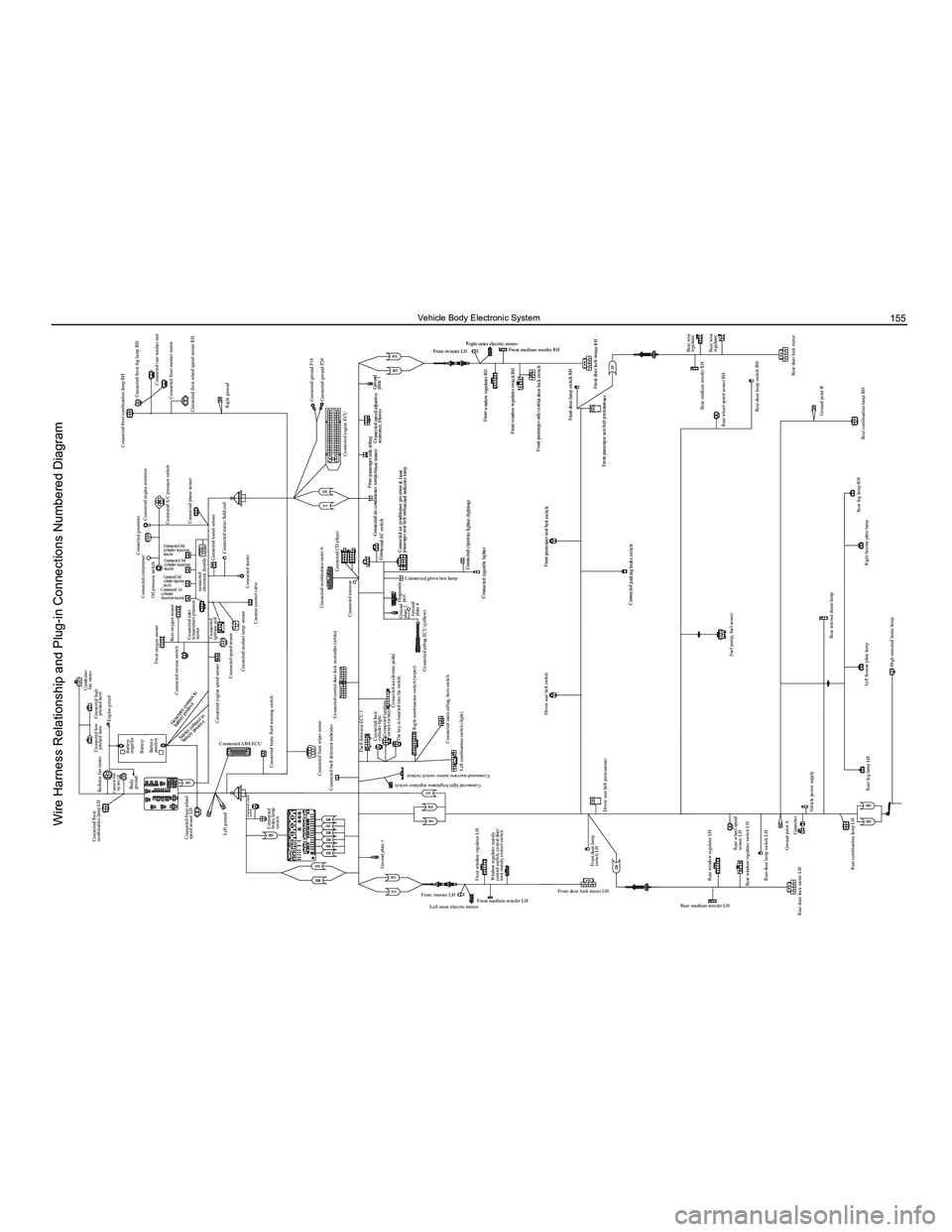
Wire Harness Relationship and Plug-in Connections Numbered Diagram
Page 182 of 281
Downloaded from www.Manualslib.com manuals search engine 175Vehicle Body Electronic System
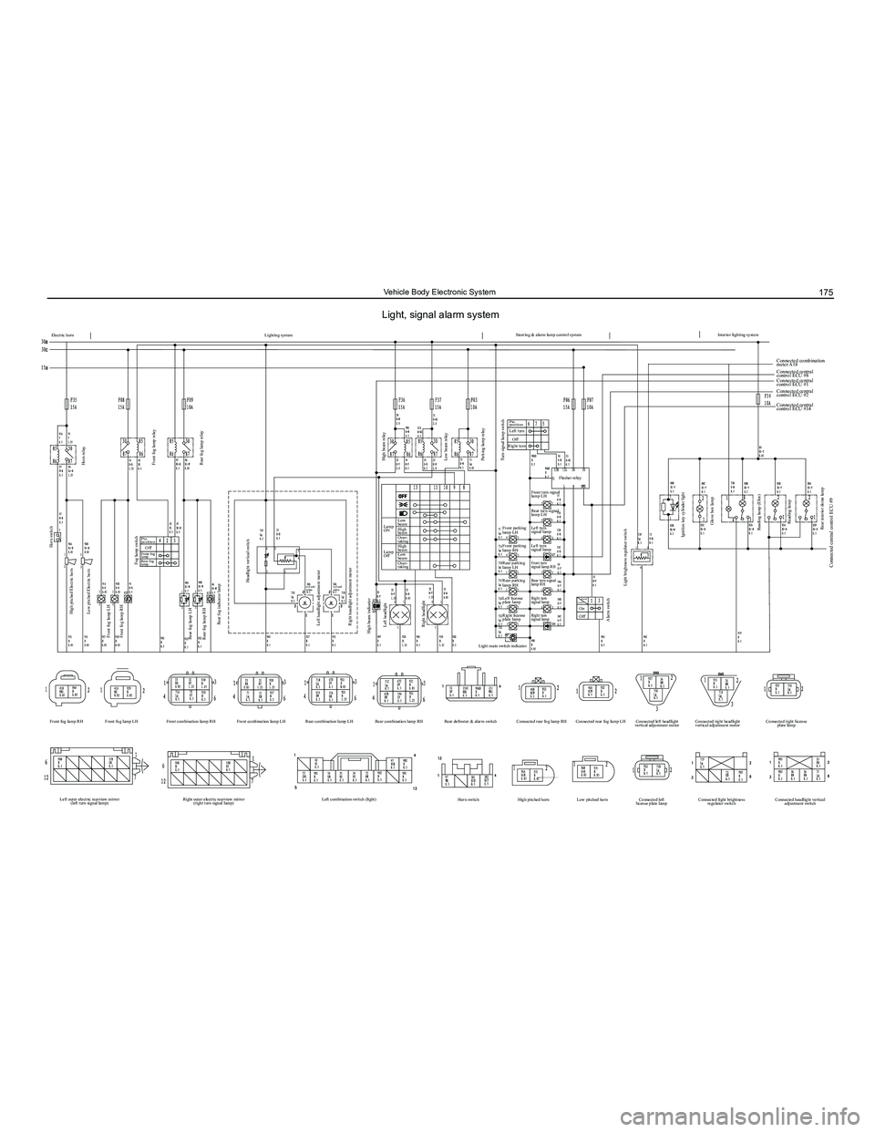
Electric horn
Horn switch
High pitched Electric horn
Low pitched Electric horn
Front fog lamp LH
Front fog lamp RH
Left outer electric rearview mirror (left turn signal lamp) Right outer electric rearview mirror
(right turn signal lamp) Left combination switch (light)
Horn switch High pitched horn Low pitched horn Connected left
license plate lamp Connected light brightness
regulator switch Connected headlight vertical
adjustment switch
Front fog lamp LH
Front combination lamp RH Front combination lamp LH Rear combination lamp LH Rear combination lamp RH Rear defroster & alarm switch Connected rear fog lamp RH Connected rear fog lamp LH Connected left headlight
vertical adjustment motor Connected right headlight
vertical adjustment motor Connected right license
plate lamp
Front fog lamp RH
Rear fog lamp LH
Rear fog lamp RH
Rear fog indicator lamp
Left headlight adjustment motor
Right headlight adjustment motor High beam relay
Lamp
ON Low
beam
Low
beam High
beam
High
beam Over-
taking
Over-
taking
Lamp
Off
Low beam relay
Parking lamp relay
Flasher relay
Connected combination
meter A18
Connected central
control ECU #8
Connected central
control ECU #1
Connected central
control ECU #2
Connected central
control ECU #14
Front parking
lamp LH Front turn signal
lamp LH
Rear turn signal
lamp LH
Left turn
signal lamp
Left turn
signal lamp
Front turn
signal lamp RH
Rear turn signal
lamp RH
Right turn
signal lamp
Right turn
signal lamp
Front parking
lamp RH
Rear parking
lamp LH
Rear parking
lamp RH
Left license
plate lamp
Right license
plate lamp
Light main switch indicator
Turn signal lamp switch
Alarm switch Light brightness regulator switch
Ignition key cylinder light Glove box lamp
Reading lamp (Elite) Reading lamp
Rear interior dome lamp
Connected central control ECU #9
High beam indicator Left headlight
Right headlight Headlight vertical switch
red and
white
red and
white
Fog lamp switch
Pin
position Pin
position
Left turn
Right turn Off
Front fog
lamp
Rear fog
lamp Off
Horn relay
Front fog lamp relay
Rear fog lamp relay
Lighting system Steering & alarm lamp control system
Interior lighting system
Terminal
Location
Off On
Light, signal alarm system
Page 200 of 281
Downloaded from www.Manualslib.com manuals search engine 193Electrical Accessories
SymptomsCausesSolutions
Cannot start
Burnt fuseReplace with a new fuse of the same
specification
Vehicle supply battery fuse is burntReplace the vehicle supply battery fuse
Illegal operation and other factorsPress the reset button to reset the system
No sound or sound is too low
The volume of the head unit or the
connected component is too low
Raise the volume of the head unit or the
connected component
Speaker possibly damagedCheck the speaker
The sound balance settings lean to one
side
Adjust the sound balance
Speaker's connection wire touches the
vehicle body
Use insulated conductor to connect the
speaker and use insulating cement to cover
the exposed connections
Disc is not genuineUse a genuine disc
Speaker is incorrectly connectedPlease refer to the "Electrical connection
diagram" to correct the connection
Common faults and solutions
General problems
CD Player
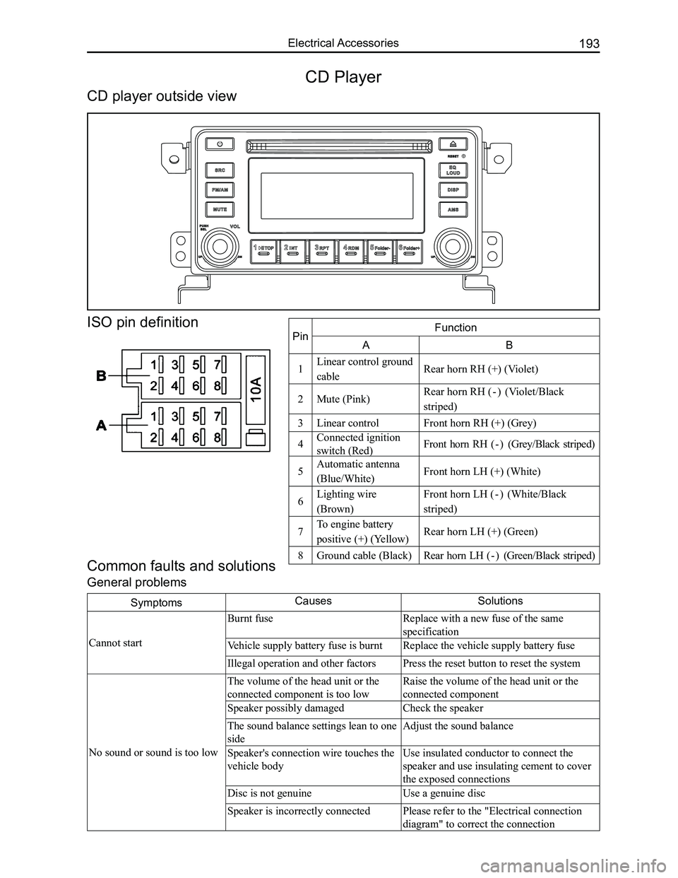
CD player outside view
ISO pin definition
PinFunction
AB
1Linear control ground
cableRear horn RH (+) (Violet)
2Mute (Pink)Rear horn RH ( - ) (Violet/Black
striped)
3Linear controlFront horn RH (+) (Grey)
4Connected ignition
switch (Red)Front horn RH ( - ) (Grey/Black striped)
5Automatic antenna
(Blue/White)Front horn LH (+) (White)
6Lighting wire
(Brown)
Front horn LH ( - ) (White/Black
striped)
7To engine battery
positive (+) (Yellow)Rear horn LH (+) (Green)
8Ground cable (Black)Rear horn LH ( - ) (Green/Black striped)
Page 201 of 281
Downloaded from www.Manualslib.com manuals search engine GWFLORID Maintenance Manual194
Display characterMalfunctionSolutions
ERR3Disc is placed upside downEject the disc and reload
ERR4Incompatible disc file or formatCheck the disc format
ERR1
ERR1Disc structure errorEject the disc and replay
Trouble code
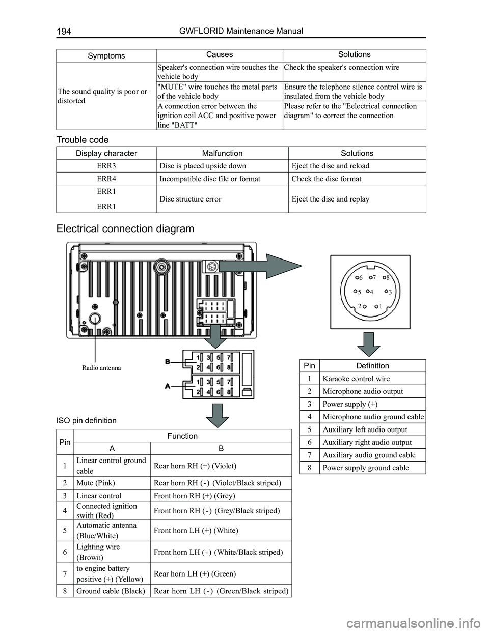
Electrical connection diagram
SymptomsCausesSolutions
The sound quality is poor or
distorted
Speaker's connection wire touches the
vehicle body
Check the speaker's connection wire
"MUTE" wire touches the metal parts
of the vehicle body
Ensure the telephone silence control wire is
insulated from the vehicle body
A connection error between the
ignition coil ACC and positive power
line "BATT"
Please refer to the "Eelectrical connection
diagram" to correct the connection
Radio antenna
12
345
678
PinDefinition
1Karaoke control wire
2Microphone audio output
3Power supply (+)
4Microphone audio ground cable
5Auxiliary left audio output
6Auxiliary right audio output
7Auxiliary audio ground cable
8Power supply ground cable
PinFunction
AB
1Linear control ground
cableRear horn RH (+) (Violet)
2Mute (Pink)Rear horn RH ( - ) (Violet/Black striped)
3Linear controlFront horn RH (+) (Grey)
4Connected ignition
swith (Red)Front horn RH ( - ) (Grey/Black striped)
5Automatic antenna
(Blue/White)Front horn LH (+) (White)
6Lighting wire
(Brown)Front horn LH ( - ) (White/Black striped)
7to engine battery
positive (+) (Yellow)Rear horn LH (+) (Green)
8Ground cable (Black)Rear horn LH ( - ) (Green/Black striped)
ISO pin definition
Page 236 of 281
Downloaded from www.Manualslib.com manuals search engine 229Airbags
3. Driver side airbag module installation sequence (after steering wheel i\
nstallation is completed)
(a) Install the horn's wire harness.
(b) Install the airbag module executing equipment's (gas generator) wire harness.
(c) Place the airbag module onto the steering wheel's proper installation position (avoid heavy knocking while
placing).
(d) Tighten the airbag module mounting bolt.
(e) Connect the battery's negative (-) terminal.
(f) Inspection after installation.
Auxiliary airbag removal and installation
1. Auxiliary airbag removal
(a) Remove the glove box.
(b) Pull out the dashboard wire harness and the auxiliary airbag wire harness connectors.
(c) Remove the airbag mounting bolt.
(d) Remove the upper dashboard.
(e) Remove the auxiliary airbag's two mounting nuts.
(f) Press the buckle and remove the auxiliary airbag.
2. Installation sequence for the auxiliary airbag is reverse to the removal\
sequence.
Caution: Please do not place anything on the auxiliary airbag, as to avoid accidents while deploying
the airbag.
Operation essentials
1. Driver side airbag and steering wheel removal
Caution: The following operations should only be performed after the battery's negative (-) terminal
has been disconnected, and after the ignition switch key has been pulled\
out for 60 s.
(a) Remove the mounting screws from the two holes under the steering wheel bottom cap, and lightly pick up
the driver side airbag module.
(b) Pull out the deployed airbag module's wire harness and the horn line, and remove the airbag module\
.
Attention: Diagnose the airbag module's circuit with an electrical measuring instruments but do not
dismantle it. Face the bottom of the removed passenger side airbag upwards and store it in a clean
and dry place.
(c) Remove the steering wheel mounting bolt on the steering column.
Caution: Due to the over-tight occlusion of the spline and column, the steering wheel and steering
column may be hard to separate, in which case make sure not to use force to remove the steering
wheel. The correct method is to tighten the screw into the column just a bit, and then pull up the
steering wheel (because the steering wheel bottom is connected to the clock spring, if force is used to
remove it, it may damage it).
2. Clock spring removal
(a) After steering wheel removal is completed, remove the combination switch hood.
(b) Pull out the dashboard wire harness connectors under the clock spring.
(c) Take off the clock spring.
Caution: Store the removed clock spring in a clean and dry place.
3. Installation notes
(a) Inspection before installation, inspection of driver side airbag module.
(b) Inspect the new airbag or clock spring before installing them.
4. Driver side airbag module inspection
Inspect each of the following items. If any faults are found, replace with a new corresponding airbag module
part. Discard the old components after they have been deployed in the pr\
oper order.
(a) Whether the cover sunken or depressed, cracked, or deformed.
(b) Whether the wire harness has broken connectors and deformed terminals.
(c) Whether the gas generator's housing is sunken or depressed, cracked, or deformed.
(d) Airbag module installation status.
Caution: The specified measuring instrument cannot measure the airbag module (tube rupture) circuit
resistance. Test the resistance with a testing instrument. There is an electric current in the tube rup-
ture which may lead to accidental deployment due to static electricity a\
nd cause serious accidents.
5. Clock spring inspection
Inspect each of the following items. If any fault is found, replace with\
a new clock spring.