instrument cluster GREAT WALL FLORID 2008 Service Manual
[x] Cancel search | Manufacturer: GREAT WALL, Model Year: 2008, Model line: FLORID, Model: GREAT WALL FLORID 2008Pages: 281, PDF Size: 43.97 MB
Page 226 of 281

Downloaded from www.Manualslib.com manuals search engine 219Airbags
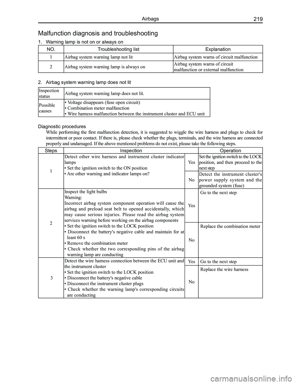
NO.Troubleshooting listExplanation
1Airbag system warning lamp not litAirbag system warns of circuit malfunction
2Airbag system warning lamp is always onAirbag system warns of circuit
malfunction or external malfunction
2. Airbag system warning lamp does not lit
Inspection
statusAirbag system warning lamp does not lit.
Possible
causes
• Voltage disappears (fuse open circuit)
• Combination meter malfunction
• Wire harness malfunction between the instrument cluster and ECU unit
Diagnostic procedures
While performing the first malfunction detection, it is suggested to wiggle the wire harness and plugs to check for
intermittent or poor contact. If there is, please check whether the plugs, terminals, and the wire harness are connected
properly and undamaged. If the above mentioned problems do not exist, pl\
ease take the following steps.
StepsInspectionOperation
1
Detect other wire harness and instrument cluster indicator
lamps
• Set the ignition switch to the ON position
• Are other warning and indicator lamps on?
Yes
Set the ignition switch to the LOCK
position, and then proceed to the
next step
No
Detect the instrument cluster's
power supply system and the
grounded system (fuse)
2
Inspect the light bulbs
Warning:
Incorrect airbag system component operation will cause the
airbag and preload seat belt to opened accidentally, which
may cause serious injuries. Please read the airbag system
services warning before working on the airbag components
• Set the ignition switch to the LOCK position
• Disconnect the battery's negative cable and maintain for at
least 60 s
• Remove the combination meter
• Check whether the two corresponding pins of the airbag
warning lamp are conducting
Yes
Go to the next step
No
Replace the combination meter
3
Detect the wire harness connection between the ECU unit and
the instrument cluster
• Set the ignition switch to the LOCK position
• Disconnect the battery's negative cable
• Disconnect the instrument cluster plugs
• Check whether the warning lamp's corresponding circuits
are conducting
YesGo to the next step
No
Replace the wire harness
Malfunction diagnosis and troubleshooting
1. Warning lamp is not on or always on
Page 227 of 281

Downloaded from www.Manualslib.com manuals search engine GWFLORID Maintenance Manual220
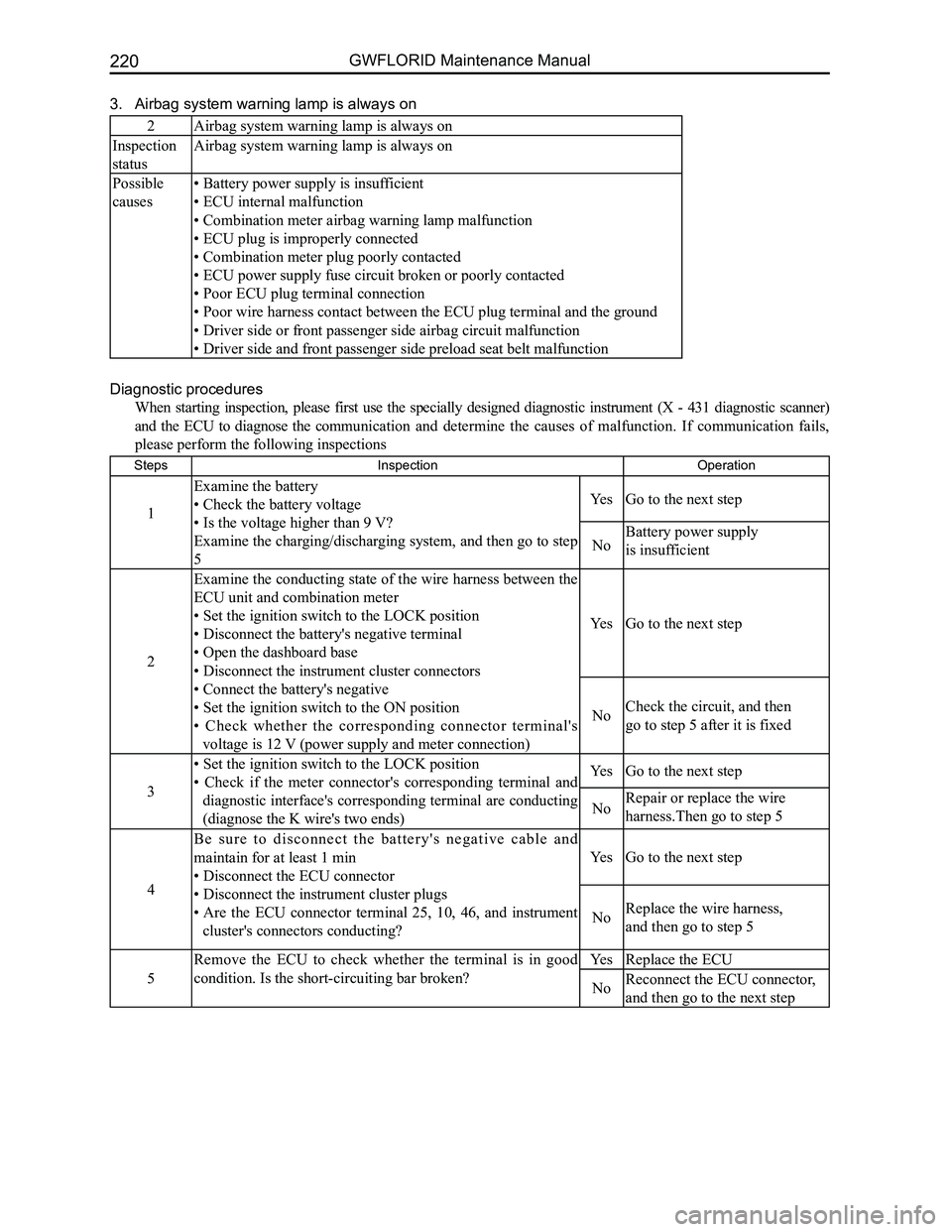
3. Airbag system warning lamp is always on
2Airbag system warning lamp is always on
Inspection
status
Airbag system warning lamp is always on
Possible
causes
• Battery power supply is insufficient
• ECU internal malfunction
• Combination meter airbag warning lamp malfunction
• ECU plug is improperly connected
• Combination meter plug poorly contacted
• ECU power supply fuse circuit broken or poorly contacted
• Poor ECU plug terminal connection
• Poor wire harness contact between the ECU plug terminal and the ground
• Driver side or front passenger side airbag circuit malfunction
• Driver side and front passenger side preload seat belt malfunction
Diagnostic procedures
When starting inspection, please first use the specially designed diagnostic instrument (X - 431 diagnostic scanner)
and the ECU to diagnose the communication and determine the causes of malfunction. If communication fails,
please perform the following inspections
StepsInspection Operation
1
Examine the battery
• Check the battery voltage
• Is the voltage higher than 9 V?
Examine the charging/discharging system, and then go to step
5
YesGo to the next step
NoBattery power supply
is insufficient
2
Examine the conducting state of the wire harness between the
ECU unit and combination meter
• Set the ignition switch to the LOCK position
• Disconnect the battery's negative terminal
• Open the dashboard base
• Disconnect the instrument cluster connectors
• Connect the battery's negative
• Set the ignition switch to the ON position
• Check whether the corresponding connector terminal's
voltage is 12 V (power supply and meter connection)
YesGo to the next step
NoCheck the circuit, and then
go to step 5 after it is fixed
3
• Set the ignition switch to the LOCK position
• Check if the meter connector's corresponding terminal and
diagnostic interface's corresponding terminal are conducting
(diagnose the K wire's two ends)
YesGo to the next step
NoRepair or replace the wire
harness.Then go to step 5
4
B e s u r e t o d i s c o n n e c t t h e b a t t e r y ' s n e g a t i v e c a b l e a n d
maintain for at least 1 min
• Disconnect the ECU connector
• Disconnect the instrument cluster plugs
• Are the ECU connector terminal 25, 10, 46, and instrument
cluster's connectors conducting?
YesGo to the next step
NoReplace the wire harness,
and then go to step 5
5
Remove the ECU to check whether the terminal is in good
condition. Is the short-circuiting bar broken?
YesReplace the ECU
NoReconnect the ECU connector,
and then go to the next step