low beam GREAT WALL FLORID 2008 Service Manual
[x] Cancel search | Manufacturer: GREAT WALL, Model Year: 2008, Model line: FLORID, Model: GREAT WALL FLORID 2008Pages: 281, PDF Size: 43.97 MB
Page 2 of 281
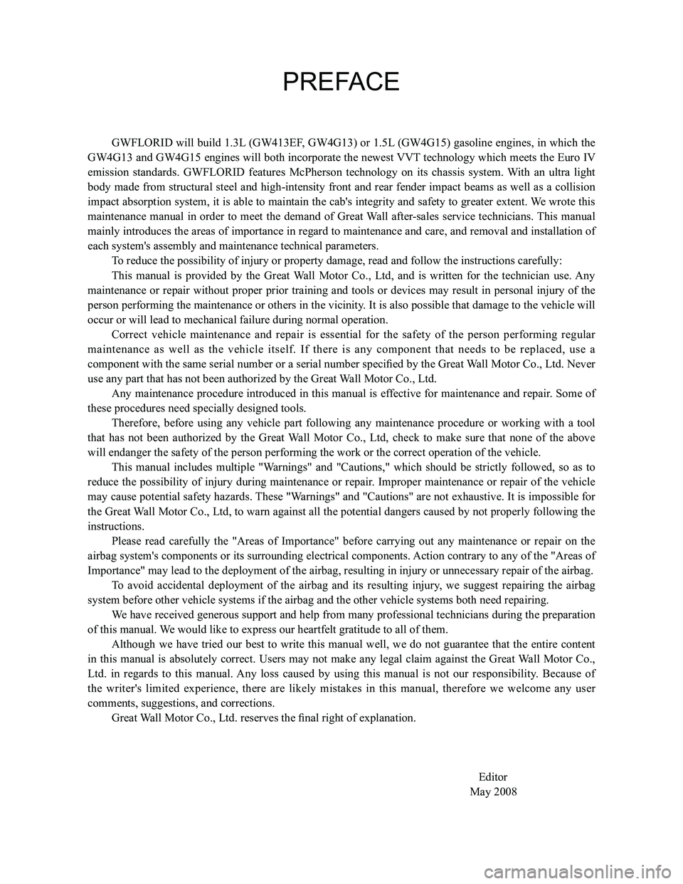
Downloaded from www.Manualslib.com manuals search engine PREFACE
GWFLORID will build 1.3L (GW413EF, GW4G13) or 1.5L (GW4G15) gasoline engines, in which the
GW4G13 and GW4G15 engines will both incorporate the newest VVT technology which meets the Euro IV
emission standards. GWFLORID features McPherson technology on its chassis system. With an ultra light
body made from structural steel and high-intensity front and rear fender impact beams as well as a collision
impact absorption system, it is able to maintain the cab's integrity and safety to greater extent. We wrote this
maintenance manual in order to meet the demand of Great Wall after-sales service technicians. This manual
mainly introduces the areas of importance in regard to maintenance and care, and removal and installation of
each system's assembly and maintenance technical parameters.
To reduce the possibility of injury or property damage, read and follow t\
he instructions carefully:
This manual is provided by the Great Wall Motor Co., Ltd, and is written for the technician use. Any
maintenance or repair without proper prior training and tools or devices may result in personal injury of the
person performing the maintenance or others in the vicinity. It is also possible that damage to the vehicle will
occur or will lead to mechanical failure during normal operation.
Correct vehicle maintenance and repair is essential for the safety of the person performing regular
maintenance as well as the vehicle itself. If there is any component that needs to be replaced, use a
component with the same serial number or a serial number specified by the Great Wall Motor Co., Ltd. Never
use any part that has not been authorized by the Great Wall Motor Co., Ltd.
Any maintenance procedure introduced in this manual is effective for maintenance and repair. Some of
these procedures need specially designed tools.
Therefore, before using any vehicle part following any maintenance procedure or working with a tool
that has not been authorized by the Great Wall Motor Co., Ltd, check to make sure that none of the above
will endanger the safety of the person performing the work or the correc\
t operation of the vehicle.
This manual includes multiple "Warnings" and "Cautions," which should be strictly followed, so as to
reduce the possibility of injury during maintenance or repair. Improper maintenance or repair of the vehicle
may cause potential safety hazards. These "Warnings" and "Cautions" are not exhaustive. It is impossible for
the Great Wall Motor Co., Ltd, to warn against all the potential dangers caused by not properly following the
instructions.
Please read carefully the "Areas of Importance" before carrying out any maintenance or repair on the
airbag system's components or its surrounding electrical components. Action contrary to any of the "Areas of
Importance" may lead to the deployment of the airbag, resulting in injur\
y or unnecessary repair of the airbag.
To avoid accidental deployment of the airbag and its resulting injury, we suggest repairing the airbag
system before other vehicle systems if the airbag and the other vehicle \
systems both need repairing.
We have received generous support and help from many professional technicians during the preparation
of this manual. We would like to express our heartfelt gratitude to all of them.
Although we have tried our best to write this manual well, we do not guarantee that the entire content
in this manual is absolutely correct. Users may not make any legal claim against the Great Wall Motor Co.,
Ltd. in regards to this manual. Any loss caused by using this manual is not our responsibility. Because of
the writer's limited experience, there are likely mistakes in this manual, therefore we welcome any user
comments, suggestions, and corrections.
Great Wall Motor Co., Ltd. reserves the final right of explanation.
\
Editor
May 2008
Page 23 of 281
Downloaded from www.Manualslib.com manuals search engine GWFLORID Maintenance Manual16
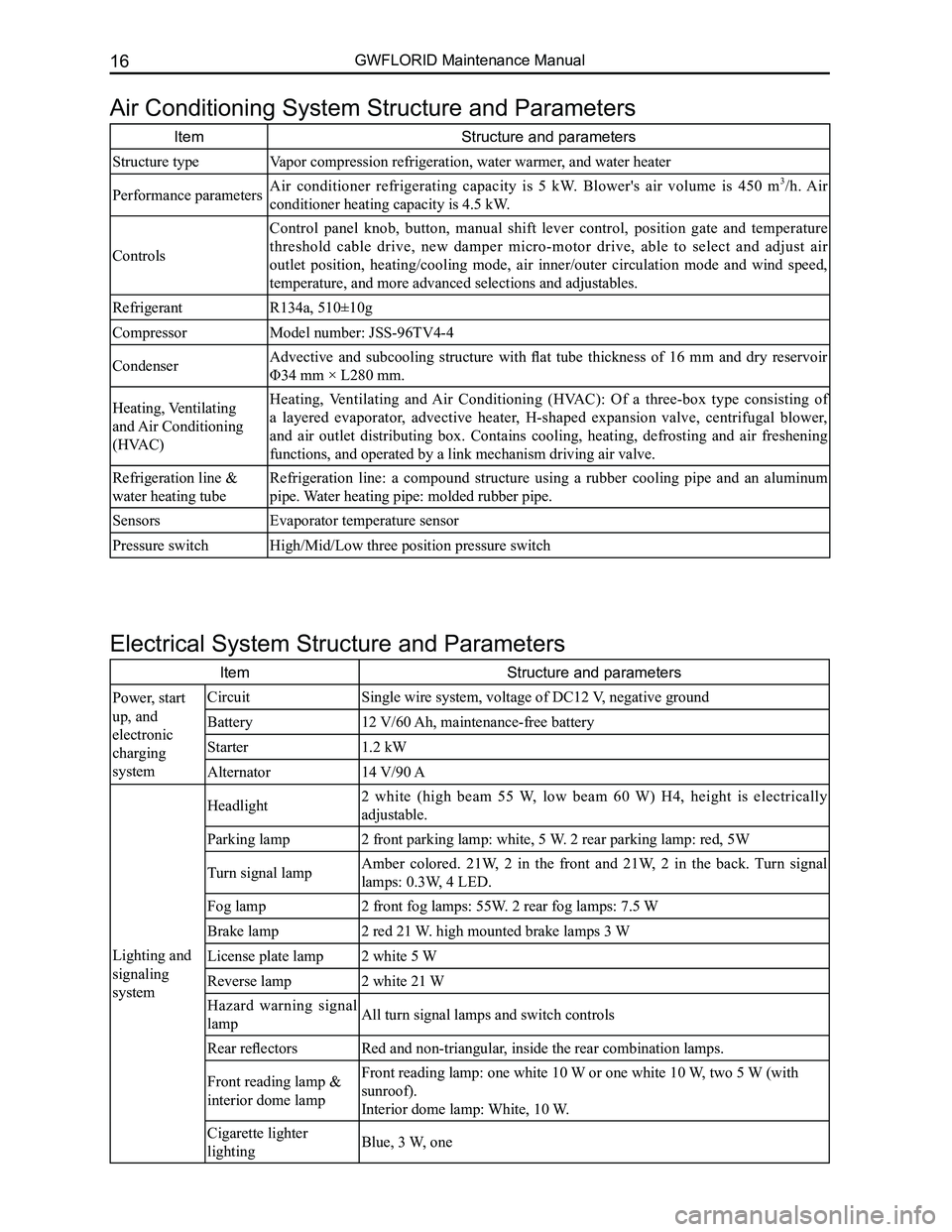
Air Conditioning System Structure and Parameters
ItemStructure and parameters
Structure typeVapor compression refrigeration, water warmer, and water heater
Performance parametersAir conditioner refrigerating capacity is 5 kW. Blower's air volume is 450 m3/h. Air
conditioner heating capacity is 4.5 kW.
Controls
Control panel knob, button, manual shift lever control, position gate and temperature
threshold cable drive, new damper micro-motor drive, able to select and adjust air
outlet position, heating/cooling mode, air inner/outer circulation mode and wind speed,
temperature, and more advanced selections and adjustables.
RefrigerantR134a, 510±10g
CompressorModel number: JSS-96TV4-4
CondenserAdvective and subcooling structure with flat tube thickness of 16 mm and dry reservoir
Φ34 mm × L280 mm.
Heating, Ventilating
and Air Conditioning
(HVAC)
Heating, Ventilating and Air Conditioning (HVAC): Of a three-box type consisting of
a layered evaporator, advective heater, H-shaped expansion valve, centrifugal blower,
and air outlet distributing box. Contains cooling, heating, defrosting and air freshening
functions, and operated by a link mechanism driving air valve.
Refrigeration line &
water heating tube
Refrigeration line: a compound structure using a rubber cooling pipe and an aluminum
pipe. Water heating pipe: molded rubber pipe.
SensorsEvaporator temperature sensor
Pressure switchHigh/Mid/Low three position pressure switch
Electrical System Structure and Parameters
ItemStructure and parameters
Power, start
up, and
electronic
charging
system
CircuitSingle wire system, voltage of DC12 V, negative ground
Battery12 V/60 Ah, maintenance-free battery
Starter1.2 kW
Alternator14 V/90 A
Lighting and
signaling
system
Headlight2 white (high beam 55 W, low beam 60 W) H4, height is electrically
adjustable.
Parking lamp2 front parking lamp: white, 5 W. 2 rear parking lamp: red, 5W
Turn signal lampAmber colored. 21W, 2 in the front and 21W, 2 in the back. Turn signal
lamps: 0.3W, 4 LED.
Fog lamp2 front fog lamps: 55W. 2 rear fog lamps: 7.5 W
Brake lamp2 red 21 W. high mounted brake lamps 3 W
License plate lamp2 white 5 W
Reverse lamp2 white 21 W
Hazard warning signal
lampAll turn signal lamps and switch controls
Rear reflectorsRed and non-triangular, inside the rear combination lamps.
Front reading lamp &
interior dome lamp
Front reading lamp: one white 10 W or one white 10 W, two 5 W (with
sunroof).
Interior dome lamp: White, 10 W.
Cigarette lighter
lightingBlue, 3 W, one
Page 24 of 281
Downloaded from www.Manualslib.com manuals search engine 17Overall Parameters
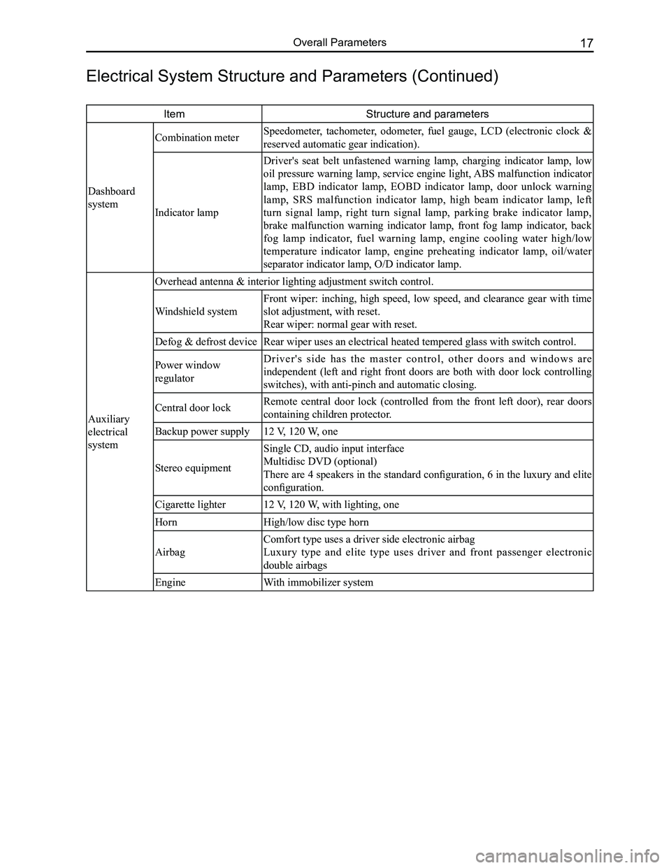
ItemStructure and parameters
Dashboard
system
Combination meter Speedometer, tachometer, odometer, fuel gauge, LCD (electronic clock &
reserved automatic gear indication).
Indicator lamp
Driver's seat belt unfastened warning lamp, charging indicator lamp, low
oil pressure warning lamp, service engine light, ABS malfunction indicator
lamp, EBD indicator lamp, EOBD indicator lamp, door unlock warning
lamp, SRS malfunction indicator lamp, high beam indicator lamp, left
turn signal lamp, right turn signal lamp, parking brake indicator lamp,
brake malfunction warning indicator lamp, front fog lamp indicator, back
fog lamp indicator, fuel warning lamp, engine cooling water high/low
temperature indicator lamp, engine preheating indicator lamp, oil/water
separator indicator lamp, O/D indicator lamp.
Auxiliary
electrical
system
Overhead antenna & interior lighting adjustment switch control.
Windshield system
Front wiper: inching, high speed, low speed, and clearance gear with time
slot adjustment, with reset.
Rear wiper: normal gear with reset.
Defog & defrost deviceRear wiper uses an electrical heated tempered glass with switch control.\
Power window
regulator
D r i v e r ' s s i d e h a s t h e m a s t e r c o n t r o l , o t h e r d o o r s a n d w i n d o w s a r e
independent (left and right front doors are both with door lock controlling
switches), with anti-pinch and automatic closing.
Central door lockRemote central door lock (controlled from the front left door), rear doors
containing children protector.
Backup power supply12 V, 120 W, one
Stereo equipment
Single CD, audio input interface
Multidisc DVD (optional)
There are 4 speakers in the standard configuration, 6 in the luxury and elite
configuration.
Cigarette lighter12 V, 120 W, with lighting, one
HornHigh/low disc type horn
Airbag
Comfort type uses a driver side electronic airbag
Luxury type and elite type uses driver and front passenger electronic
double airbags
EngineWith immobilizer system
Electrical System Structure and Parameters (Continued)
Page 26 of 281
Downloaded from www.Manualslib.com manuals search engine 19Overall Parameters
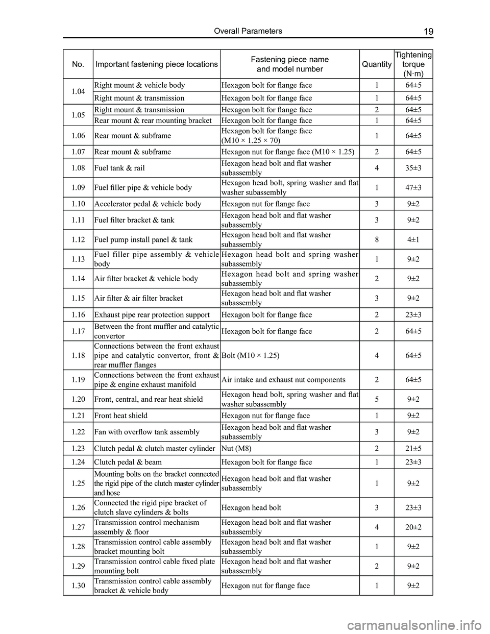
No.Important fastening piece locationsFastening piece name
and model numberQuantity
Tightening
torque
(N·m)
1.04Right mount & vehicle bodyHexagon bolt for flange face164±5
Right mount & transmissionHexagon bolt for flange face 164±5
1.05Right mount & transmissionHexagon bolt for flange face 264±5
Rear mount & rear mounting bracketHexagon bolt for flange face 164±5
1.06Rear mount & subframeHexagon bolt for flange face
(M10 × 1.25 × 70)164±5
1.07Rear mount & subframeHexagon nut for flange face (M10 × 1.25)264±5
1.08Fuel tank & railHexagon head bolt and flat washer
subassembly435±3
1.09Fuel filler pipe & vehicle bodyHexagon head bolt, spring washer and flat
washer subassembly147±3
1.10Accelerator pedal & vehicle bodyHexagon nut for flange face39±2
1.11Fuel filter bracket & tankHexagon head bolt and flat washer
subassembly39±2
1.12Fuel pump install panel & tankHexagon head bolt and flat washer
subassembly84±1
1.13Fuel filler pipe assembly & vehicle
body
H e x a g o n h e a d b o l t a n d s p r i n g w a s h e r
subassembly19±2
1.14Air filter bracket & vehicle bodyH e x a g o n h e a d b o l t a n d s p r i n g w a s h e r
subassembly29±2
1.15Air filter & air filter bracketHexagon head bolt and flat washer
subassembly39±2
1.16Exhaust pipe rear protection supportHexagon bolt for flange face223±3
1.17Between the front muffler and catalytic
convertorHexagon bolt for flange face264±5
1.18
Connections between the front exhaust
pipe and catalytic convertor, front &
rear muffler flanges
Bolt (M10 × 1.25)464±5
1.19Connections between the front exhaust
pipe & engine exhaust manifoldAir intake and exhaust nut components264±5
1.20Front, central, and rear heat shieldHexagon head bolt, spring washer and flat
washer subassembly59±2
1.21Front heat shieldHexagon nut for flange face19±2
1.22Fan with overflow tank assemblyHexagon head bolt and flat washer
subassembly39±2
1.23Clutch pedal & clutch master cylinderNut (M8)221±5
1.24Clutch pedal & beamHexagon bolt for flange face123±3
1.25
Mounting bolts on the bracket connected
the rigid pipe of the clutch master cylinder
and hose
Hexagon head bolt and flat washer
subassembly19±2
1.26Connected the rigid pipe bracket of
clutch slave cylinders & boltsHexagon head bolt323±3
1.27Transmission control mechanism
assembly & floor
Hexagon head bolt and flat washer
subassembly420±2
1.28Transmission control cable assembly
bracket mounting bolt
Hexagon head bolt and flat washer
subassembly19±2
1.29Transmission control cable fixed plate
mounting bolt
Hexagon head bolt and flat washer
subassembly29±2
1.30Transmission control cable assembly
bracket & vehicle bodyHexagon nut for flange face19±2
Page 79 of 281
Downloaded from www.Manualslib.com manuals search engine GWFLORID Maintenance Manual72
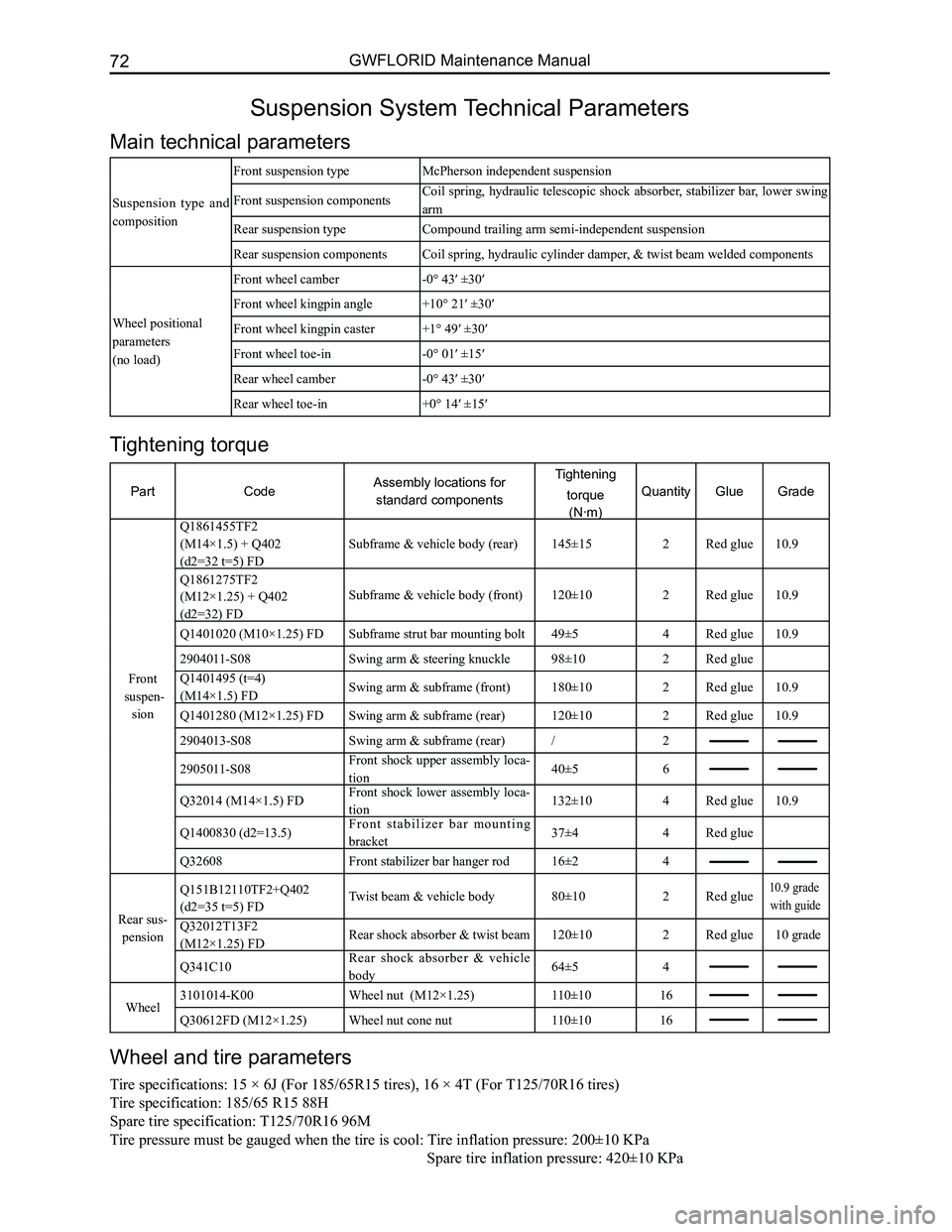
Suspension System Technical Parameters
Main technical parameters
Suspension type and
composition
Front suspension typeMcPherson independent suspension
Front suspension componentsCoil spring, hydraulic telescopic shock absorber, stabilizer bar, lower swing
arm
Rear suspension typeCompound trailing arm semi-independent suspension
Rear suspension componentsCoil spring, hydraulic cylinder damper, & twist beam welded components
Wheel positional
parameters
(no load)
Front wheel camber-0° 43′ ±30′
Front wheel kingpin angle+10° 21′ ±30′
Front wheel kingpin caster+1° 49′ ±30′
Front wheel toe-in-0° 01′ ±15′
Rear wheel camber-0° 43′ ±30′
Rear wheel toe-in+0° 14′ ±15′
Wheel and tire parameters
Tire specifications: 15 × 6J (For 185/65R15 tires), 16 × 4T (For T125/70R16 tires)
Tire specification: 185/65 R15 88H
Spare tire specification: T125/70R16 96M
Tire pressure must be gauged when the tire is cool: Tire inflation pressure: 200±10 KPa
Spare tir e inflation pressure: 420±10 KPa
Tightening torque
PartCodeAssembly locations for
standard components
Tightening
torque
(N·m)
QuantityGlueGrade
Front
suspen-
sion
Q1861455TF2
(M14×1.5) + Q402
(d2=32 t=5) FD
Subframe & vehicle body (rear)145±15 2Red glue10.9
Q1861275TF2
(M12×1.25) + Q402
(d2=32) FD
Subframe & vehicle body (front)120±102Red glue10.9
Q1401020 (M10×1.25) FDSubframe strut bar mounting bolt49±54Red glue10.9
2904011-S08Swing arm & steering knuckle98±102Red glue
Q1401495 (t=4)
(M14×1.5) FDSwing arm & subframe (front)180±102Red glue10.9
Q1401280 (M12×1.25) FDSwing arm & subframe (rear)120±102Red glue10.9
2904013-S08Swing arm & subframe (rear)/2
2905011-S08Front shock upper assembly loca-
tion40±56
Q32014 (M14×1.5) FDFront shock lower assembly loca-
tion132±104Red glue10.9
Q1400830 (d2=13.5)F r o n t s t a b i l i z e r b a r m o u n t i n g
bracket37±44Red glue
Q32608Front stabilizer bar hanger rod16±24
Rear sus-
pension
Q151B12110TF2+Q402
(d2=35 t=5) FDTwist beam & vehicle body80±102Red glue10.9 grade
with guide
Q32012T13F2
(M12×1.25) FDRear shock absorber & twist beam120±102Red glue10 grade
Q341C10Rear shock absorber & vehicle
body64±54
Wheel3101014-K00Wheel nut (M12×1.25)110±1016
Q30612FD (M12×1.25)Wheel nut cone nut110±1016
Page 93 of 281
Downloaded from www.Manualslib.com manuals search engine GWFLORID Maintenance Manual86
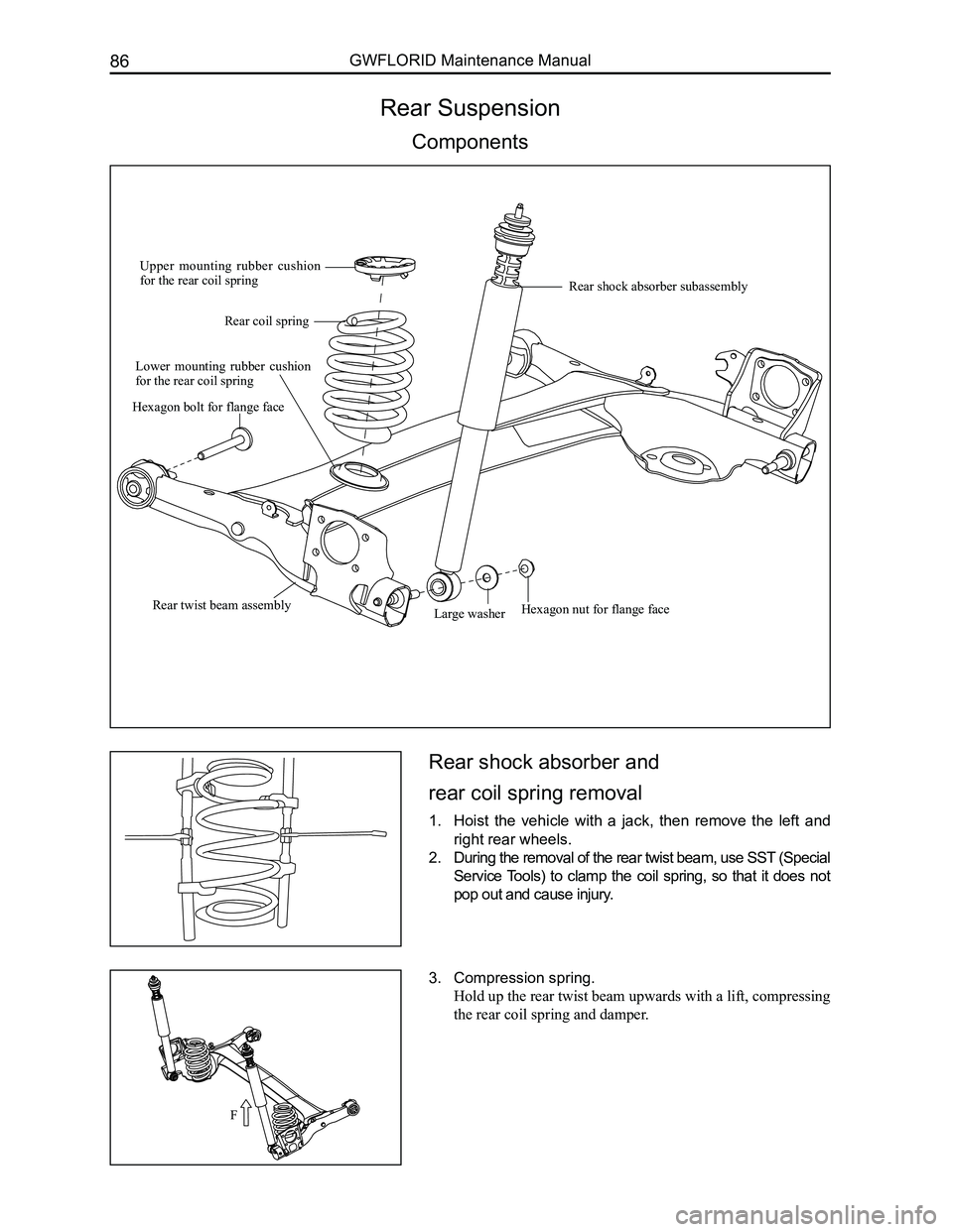
Rear Suspension
Components
Rear shock absorber and
rear coil spring removal
1. Hoist the vehicle with a jack, then remove the left and
right rear wheels.
2. During the removal of the rear twist beam, use SST (Special
Service Tools) to clamp the coil spring, so that it does not
pop out and cause injury.
3. Compression spring.
Hold up the rear twist beam upwards with a lift, compressing
the rear coil spring and damper.
Upper mounting rubber cushion for the rear coil spring
Rear coil spring
Lower mounting rubber cushion for the rear coil spring
Large washerRear twist beam assembly
Rear shock absorber subassembly
Hexagon bolt for flange face
Hexagon nut for flange face
F
Page 94 of 281
Downloaded from www.Manualslib.com manuals search engine 87Suspension System
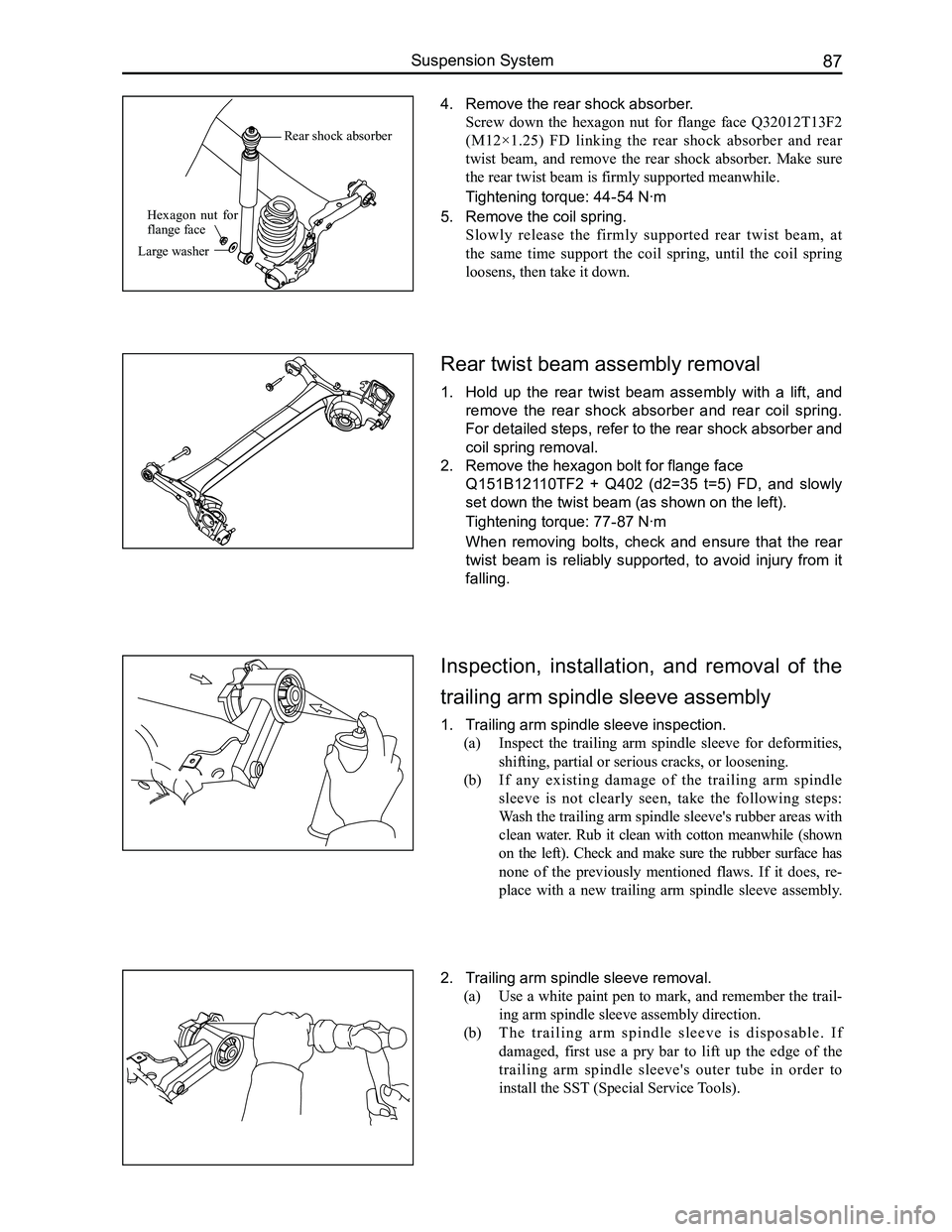
Inspection, installation, and removal of the
trailing arm spindle sleeve assembly
1. Trailing arm spindle sleeve inspection.
(a) Inspect the trailing arm spindle sleeve for deformities,
shifting, partial or serious cracks, or loosening.
(b) If any existing damage of the trailing arm spindle
sleeve is not clearly seen, take the following steps:
Wash the trailing arm spindle sleeve's rubber areas with
clean water. Rub it clean with cotton meanwhile (shown
on the left). Check and make sure the rubber surface has
none of the previously mentioned flaws. If it does, re-
place with a new trailing arm spindle sleeve assembly.
2. Trailing arm spindle sleeve removal.
(a) Use a white paint pen to mark, and remember the trail-
ing arm spindle sleeve assembly direction.
(b) T h e t r a i l i n g a r m s p i n d l e s l e e v e i s d i s p o s a b l e . I f
damaged, first use a pry bar to lift up the edge of the
trailing arm spindle sleeve's outer tube in order to
install the SST (Special Service Tools).
Rear twist beam assembly removal
1. Hold up the rear twist beam assembly with a lift, and
remove the rear shock absorber and rear coil spring.
For detailed steps, refer to the rear shock absorber and
coil spring removal.
2. Remove the hexagon bolt for flange face
Q151B12110TF2 + Q402 (d2=35 t=5) FD, and slowly
set down the twist beam (as shown on the left).
Tightening torque: 77-87 N·m
When removing bolts, check and ensure that the rear
twist beam is reliably supported, to avoid injury from it
falling.
4. Remove the rear shock absorber.
Screw down the hexagon nut for flange face Q32012T13F2
(M12×1.25) FD linking the rear shock absorber and rear
twist beam, and remove the rear shock absorber. Make sure
the rear twist beam is firmly supported meanwhile.
Tightening torque: 44-54 N·m
5. Remove the coil spring.
Slowly release the firmly supported rear twist beam, at
the same time support the coil spring, until the coil spring
loosens, then take it down.
Rear shock absorber
Large washer
Hexagon nut for flange face
Page 116 of 281
Downloaded from www.Manualslib.com manuals search engine 109Brake System
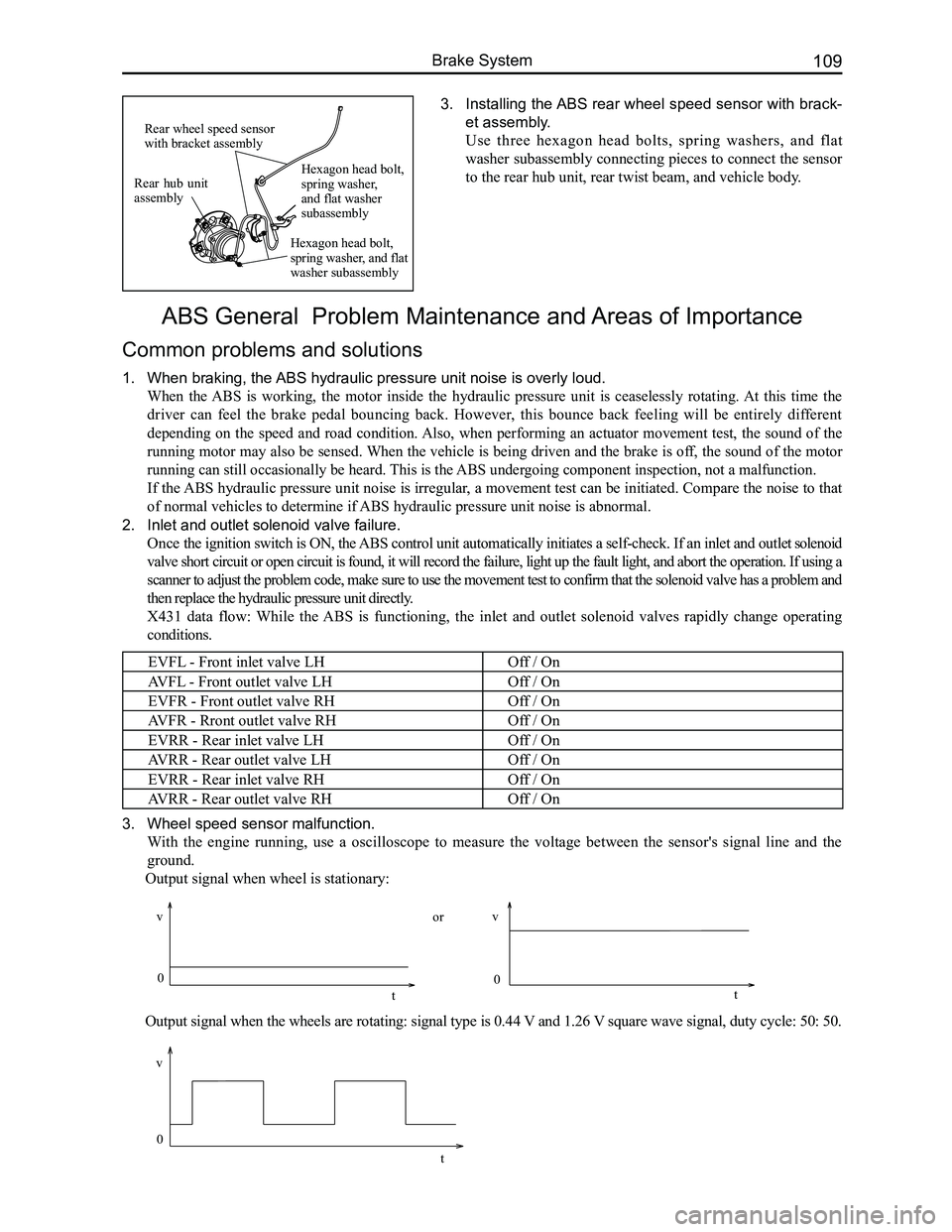
3. Installing the ABS rear wheel speed sensor with brack-
et assembly.
Use three hexagon head bolts, spring washers, and flat
washer subassembly connecting pieces to connect the sensor
to the rear hub unit, rear twist beam, and vehicle body.
ABS General Problem Maintenance and Areas of Importance
Common problems and solutions
1. When braking, the ABS hydraulic pressure unit noise is overly loud.
When the ABS is working, the motor inside the hydraulic pressure unit is ceaselessly rotating. At this time the
driver can feel the brake pedal bouncing back. However, this bounce back feeling will be entirely different
depending on the speed and road condition. Also, when performing an actuator movement test, the sound of the
running motor may also be sensed. When the vehicle is being driven and the brake is off, the sound of the motor
running can still occasionally be heard. This is the ABS undergoing component inspection, not a malfunction.
If the ABS hydraulic pressure unit noise is irregular, a movement test can be initiated. Compare the noise to that
of normal vehicles to determine if ABS hydraulic pressure unit noise is abnormal.
2. Inlet and outlet solenoid valve failure.
Once the ignition switch is ON, the ABS control unit automatically initiates a self-check. If an inlet and outlet solenoid
valve short circuit or open circuit is found, it will record the failure, light up the fault light, and abort the operation. If using a
scanner to adjust the problem code, make sure to use the movement test t\
o confirm that the solenoid valve has a problem and
then replace the hydraulic pressure unit directly.
X431 data flow: While the ABS is functioning, the inlet and outlet solenoid valves rapidly change operating
conditions.
EVFL - Front inlet valve LHOff / On
AVFL - Front outlet valve LHOff / On
EVFR - Front outlet valve RHOff / On
AVFR - Rront outlet valve RHOff / On
EVRR - Rear inlet valve LHOff / On
AVRR - Rear outlet valve LHOff / On
EVRR - Rear inlet valve RHOff / On
AVRR - Rear outlet valve RHOff / On
3. Wheel speed sensor malfunction.
With the engine running, use a oscilloscope to measure the voltage between the sensor's signal line and the
ground.
Output signal when wheel is stationary:
Output signal when the wheels are rotating: signal type is 0.44 V and 1.26 V square wave signal, duty cycle: 50: 50.
Rear hub unit assembly
Rear wheel speed sensor with bracket assembly
Hexagon head bolt, spring washer, and flat washer subassembly
Hexagon head bolt, spring washer, and flat washer subassembly
0
v
t
vv
0 0
tt
or
Page 153 of 281
Downloaded from www.Manualslib.com manuals search engine GWFLORID Maintenance Manual146
Main relay
10A backup 15A backup 25A backup
Compressor relay
Reserve
Reserve
Fuel pump
Starter relay Main
relay High
beam Low
beam
Engine ECU
Fan relay High
Starter relay High beam relay Low beam relay Reserve
Horn Reserve Reserve Fan relay Low
Fan relay Low
Fan relay High
Horn relay
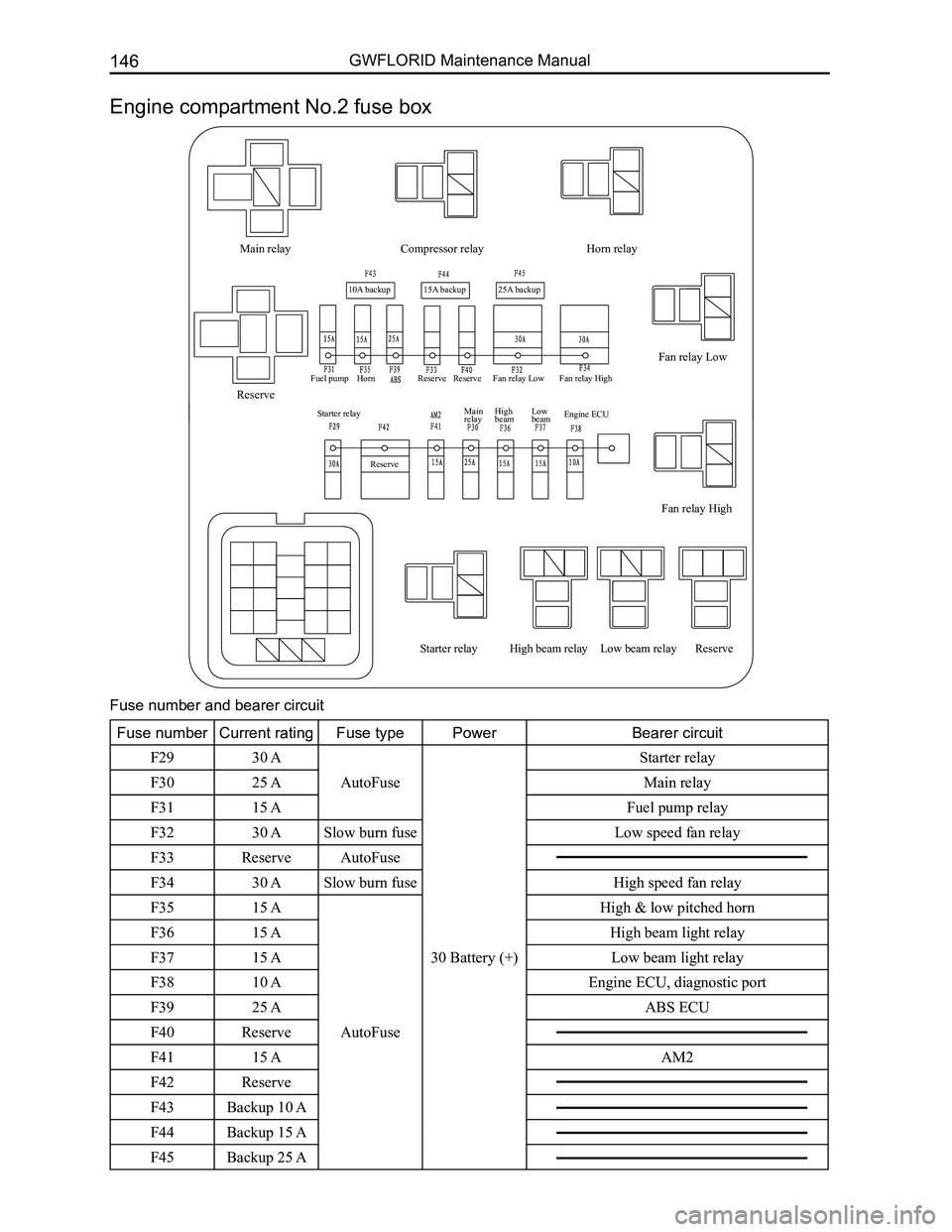
Engine compartment No.2 fuse box
Fuse number and bearer circuit
Fuse numberCurrent ratingFuse typePowerBearer circuit
F2930 A
AutoFuse
30 Battery (+)
Starter relay
F3025 AMain relay
F3115 AFuel pump relay
F3230 ASlow burn fuse Low speed fan relay
F33ReserveAutoFuse
F3430 ASlow burn fuse High speed fan relay
F3515 A
AutoFuse
High & low pitched horn
F3615 AHigh beam light relay
F3715 ALow beam light relay
F3810 AEngine ECU, diagnostic port
F3925 AABS ECU
F40Reserve
F4115 AAM2
F42Reserve
F43Backup 10 A
F44Backup 15 A
F45Backup 25 A
Page 182 of 281
Downloaded from www.Manualslib.com manuals search engine 175Vehicle Body Electronic System
Electric horn
Horn switch
High pitched Electric horn
Low pitched Electric horn
Front fog lamp LH
Front fog lamp RH
Left outer electric rearview mirror (left turn signal lamp) Right outer electric rearview mirror
(right turn signal lamp) Left combination switch (light)
Horn switch High pitched horn Low pitched horn Connected left
license plate lamp Connected light brightness
regulator switch Connected headlight vertical
adjustment switch
Front fog lamp LH
Front combination lamp RH Front combination lamp LH Rear combination lamp LH Rear combination lamp RH Rear defroster & alarm switch Connected rear fog lamp RH Connected rear fog lamp LH Connected left headlight
vertical adjustment motor Connected right headlight
vertical adjustment motor Connected right license
plate lamp
Front fog lamp RH
Rear fog lamp LH
Rear fog lamp RH
Rear fog indicator lamp
Left headlight adjustment motor
Right headlight adjustment motor High beam relay
Lamp
ON Low
beam
Low
beam High
beam
High
beam Over-
taking
Over-
taking
Lamp
Off
Low beam relay
Parking lamp relay
Flasher relay
Connected combination
meter A18
Connected central
control ECU #8
Connected central
control ECU #1
Connected central
control ECU #2
Connected central
control ECU #14
Front parking
lamp LH Front turn signal
lamp LH
Rear turn signal
lamp LH
Left turn
signal lamp
Left turn
signal lamp
Front turn
signal lamp RH
Rear turn signal
lamp RH
Right turn
signal lamp
Right turn
signal lamp
Front parking
lamp RH
Rear parking
lamp LH
Rear parking
lamp RH
Left license
plate lamp
Right license
plate lamp
Light main switch indicator
Turn signal lamp switch
Alarm switch Light brightness regulator switch
Ignition key cylinder light Glove box lamp
Reading lamp (Elite) Reading lamp
Rear interior dome lamp
Connected central control ECU #9
High beam indicator Left headlight
Right headlight Headlight vertical switch
red and
white
red and
white
Fog lamp switch
Pin
position Pin
position
Left turn
Right turn Off
Front fog
lamp
Rear fog
lamp Off
Horn relay
Front fog lamp relay
Rear fog lamp relay
Lighting system Steering & alarm lamp control system
Interior lighting system
Terminal
Location
Off On
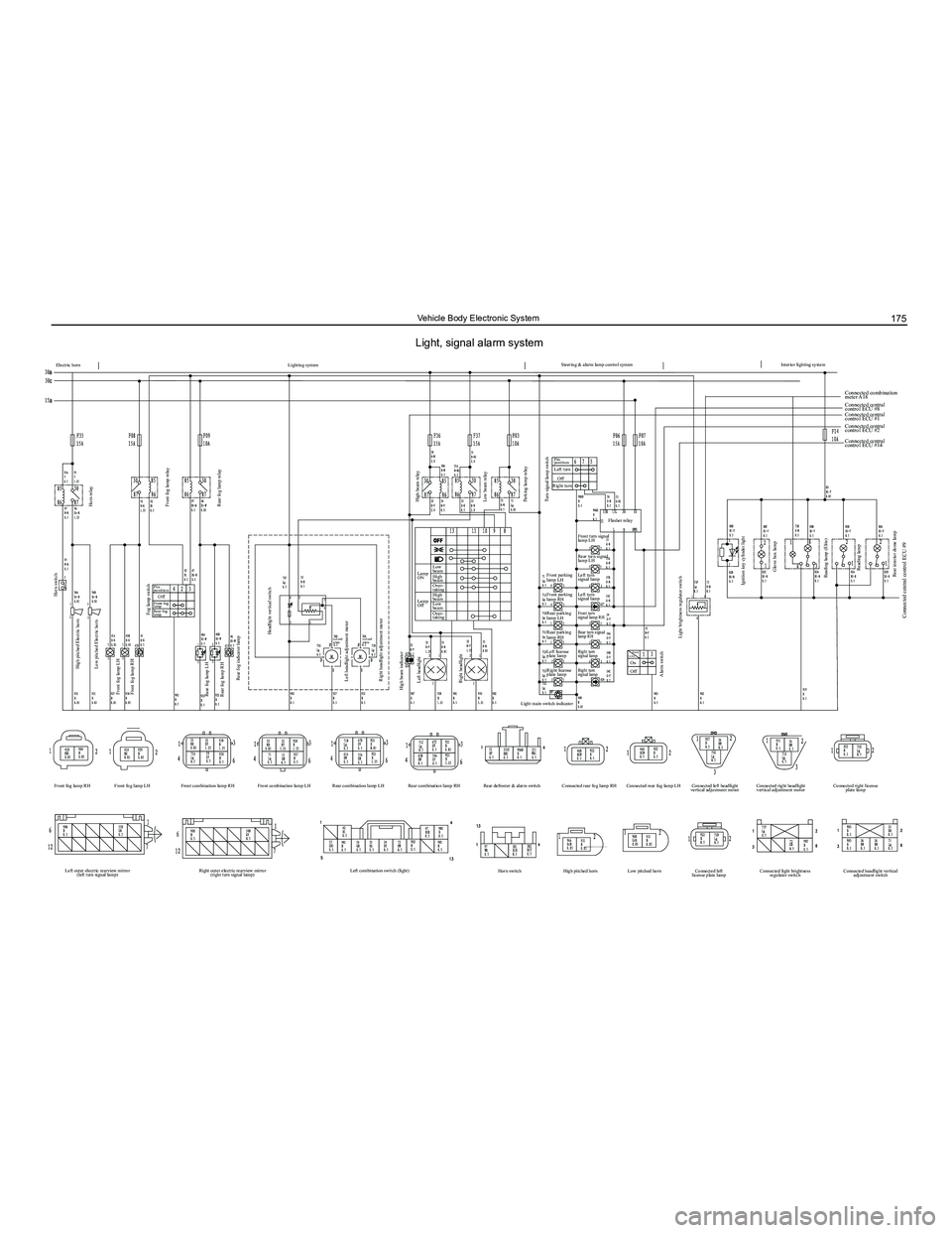
Light, signal alarm system