tow GREAT WALL FLORID 2008 Service Manual
[x] Cancel search | Manufacturer: GREAT WALL, Model Year: 2008, Model line: FLORID, Model: GREAT WALL FLORID 2008Pages: 281, PDF Size: 43.97 MB
Page 91 of 281

Downloaded from www.Manualslib.com manuals search engine GWFLORID Maintenance Manual84
Drive Shaft
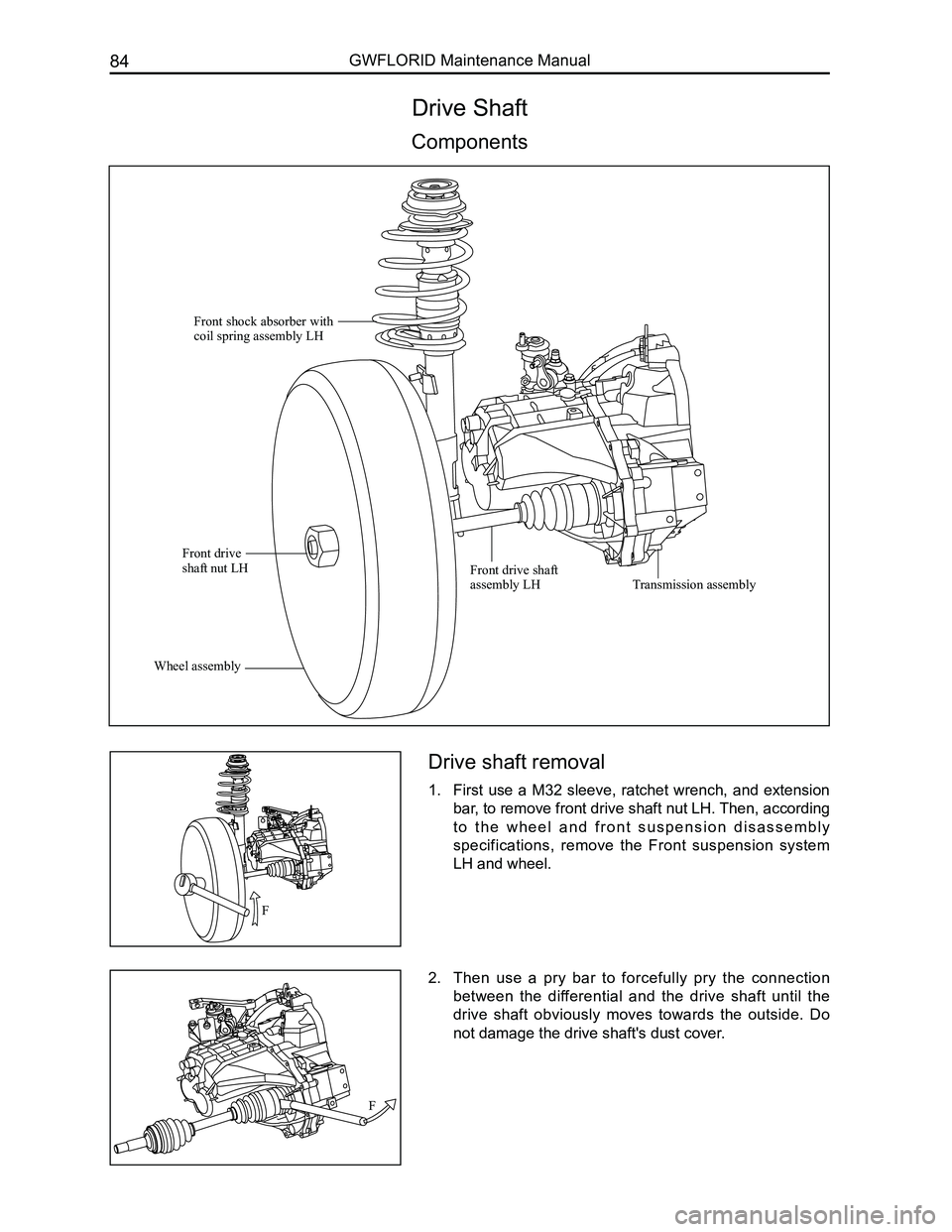
Components
Drive shaft removal
1. First use a M32 sleeve, ratchet wrench, and extension
bar, to remove front drive shaft nut LH. Then, according
t o t h e w h e e l a n d f r o n t s u s p e n s i o n d i s a s s e m b l y
specifications, remove the Front suspension system
LH and wheel.
2. Then use a pry bar to forcefully pry the connection
between the differential and the drive shaft until the
drive shaft obviously moves towards the outside. Do
not damage the drive shaft's dust cover.
Front shock absorber with coil spring assembly LH
Front drive shaft nut LH
Wheel assembly
Front drive shaft assembly LHTransmission assembly
F
F
Page 92 of 281

Downloaded from www.Manualslib.com manuals search engine 85Suspension System
Drive shaft installation
1. Insert the drive shaft.
First, align the inner end of the drive shaft and differential
spline. Keep the drive shaft axes and the differential axes
bases uniform, then hammer towards the direction of the
differential drive shaft's outer end until a clear and sharp
clicking sound is heard. Here, the drive shaft and the
transmission should have a clearance of about 1 mm.
2. According to the front suspension and wheel assembly
installation specifications, properly install the front
shock absorber with coil spring assembly LH and
wheel.
3. Use an M32 sleeve, ratchet wrench, and extension bar
to tighten front drive shaft nut LH.
Tightening torque: 225±20 N·m
F
F
Page 137 of 281

Downloaded from www.Manualslib.com manuals search engine GWFLORID Maintenance Manual130
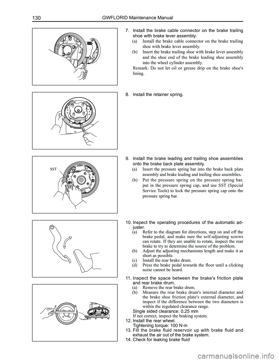
7. Install the brake cable connector on the brake trailing
shoe with brake lever assembly.
(a) Install the brake cable connector on the brake trailing
shoe with brake lever assembly.
(b) Insert the brake trailing shoe with brake lever assembly
and the shoe end of the brake leading shoe assembly
into the wheel cylinder assembly.
Remark: Do not let oil or grease drip on the brake shoe's
lining.
8. Install the retainer spring.
9. Install the brake leading and trailing shoe assemblies
onto the brake back plate assembly.
(a) Insert the pressure spring bar into the brake back plate
assembly and brake leading and trailing shoe assemblies.
(b) Put the pressure spring on the pressure spring bar,
put in the pressure spring cap, and use SST (Special
Service Tools) to lock the pressure spring cap onto the
pressure spring bar.
10. Inspect the operating procedures of the automatic ad-
juster.
(a) Refer to the diagram for directions, step on and off the
brake pedal, and make sure the self-adjusting screws
can rotate. If they are unable to rotate, inspect the rear
brake to try to determine the source of the problem.
(b) Adjust the adjusting mechanisms length and make it as
short as possible.
(c) Install the rear brake drum.
(d) Press the brake pedal towards the floor until a clicking
noise cannot be heard.
11. Inspect the space between the brake's friction plate
and rear brake drum.
(a) Remove the rear brake drum.
(b) Measure the rear brake drum's internal diameter and
the brake shoe friction plate's external diameter, and
inspect if the difference between the two diameters is
within the regulated clearance range.
Single sided clearance: 0.25 mm
If not correct, inspect the braking system.
12. Install the rear wheel.
Tightening torque: 100 N·m
13. Fill the brake fluid reservoir up with brake fluid and
exhaust the air out of the brake system.
14. Check for leaking brake fluid
SST
Page 233 of 281

Downloaded from www.Manualslib.com manuals search engine GWFLORID Maintenance Manual226
Vehicle Collision Diagnostics
Whether the airbag is deployed or not, vehicle collision diagnostic and maintenance must be conducted
according to the following procedures.
1. Check the SRS-ECU diagnostic signal
(a) Connect the diagnostic connector (X-431 diagnostic scanner).
(b) Read the diagnostic result with the X-431 diagnostic.
Caution: Due to impact, and when the battery's power supply is insufficient, the scanner will be unable
to communicate with the SRS-ECU. At this time, use an external power supply, or make sure to
perform inspection and maintenance on the dashboard's wire harness.
2. Maintenance sequence
When the airbag is deployed, the following components should be replaced\
.
(a) Driver side airbag module.
(b) Front passenger side airbag module.
(c) SRS-ECU.
(d) Driver side and front passenger side preload seat belts.
Inspect the following components, if anything is abnormal, replace with \
a new one.
(a) Clock spring.
(b) Steering wheel, steering column, and steering lower shaft components.
Installation status of the driver side airbag module regarding the steer\
ing wheel.
(a) Inspect whether the steering wheel's noise is abnormal, for improper movement, or abnormal cleara\
nce.
(b) Inspect whether the wire harness connectors are broken and whether the terminals are deformed.
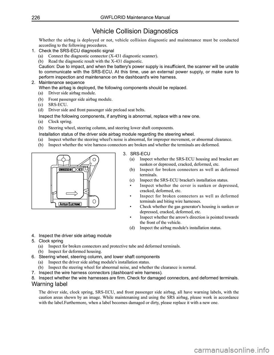
3. SRS-ECU
(a) Inspect whether the SRS-ECU housing and bracket are
sunken or depressed, cracked, deformed, etc.
(b) Inspect for broken connectors as well as deformed
terminals.
(c) Inspect the SRS-ECU bracket's installation status.
• Inspect whether the cover is sunken or depressed,
cracked, deformed, etc.
• Inspect for broken connectors as well as deformed
terminals and biting wire harnesses.
• Check whether the gas generator's housing is sunken or
depressed, cracked, deformed, etc.
• Inspect whether the arrow's direction is pointed towards
the front of the vehicle.
(d) Inspect the airbag module's installation status.
4. Inspect the driver side airbag module
5. Clock spring
(a) Inspect for broken connectors and protective tube and deformed terminals.
(b) Inspect for deformed housing.
6. Steering wheel, steering column, and lower shaft components
(a) Inspect the driver side airbag module's installation status.
(b) Inspect the steering wheel for abnormal noise, and whether the clearance is normal.
7. Inspect the wire harness connectors (dashboard wire harness).
8. Inspect whether the wire harnesses are firm. Check for damaged connectors, and deformed terminals.
Warning label
The driver side, clock spring, SRS-ECU, and front passenger side airbag, all have warning labels, with the
caution areas shown by an image. While maintenaning and using the SRS airbag, please work in accordance
with the label.Furthermore, when a label becomes damaged or dirty, please replace it with a new one.