steering GREAT WALL FLORID 2008 Service Manual
[x] Cancel search | Manufacturer: GREAT WALL, Model Year: 2008, Model line: FLORID, Model: GREAT WALL FLORID 2008Pages: 281, PDF Size: 43.97 MB
Page 5 of 281
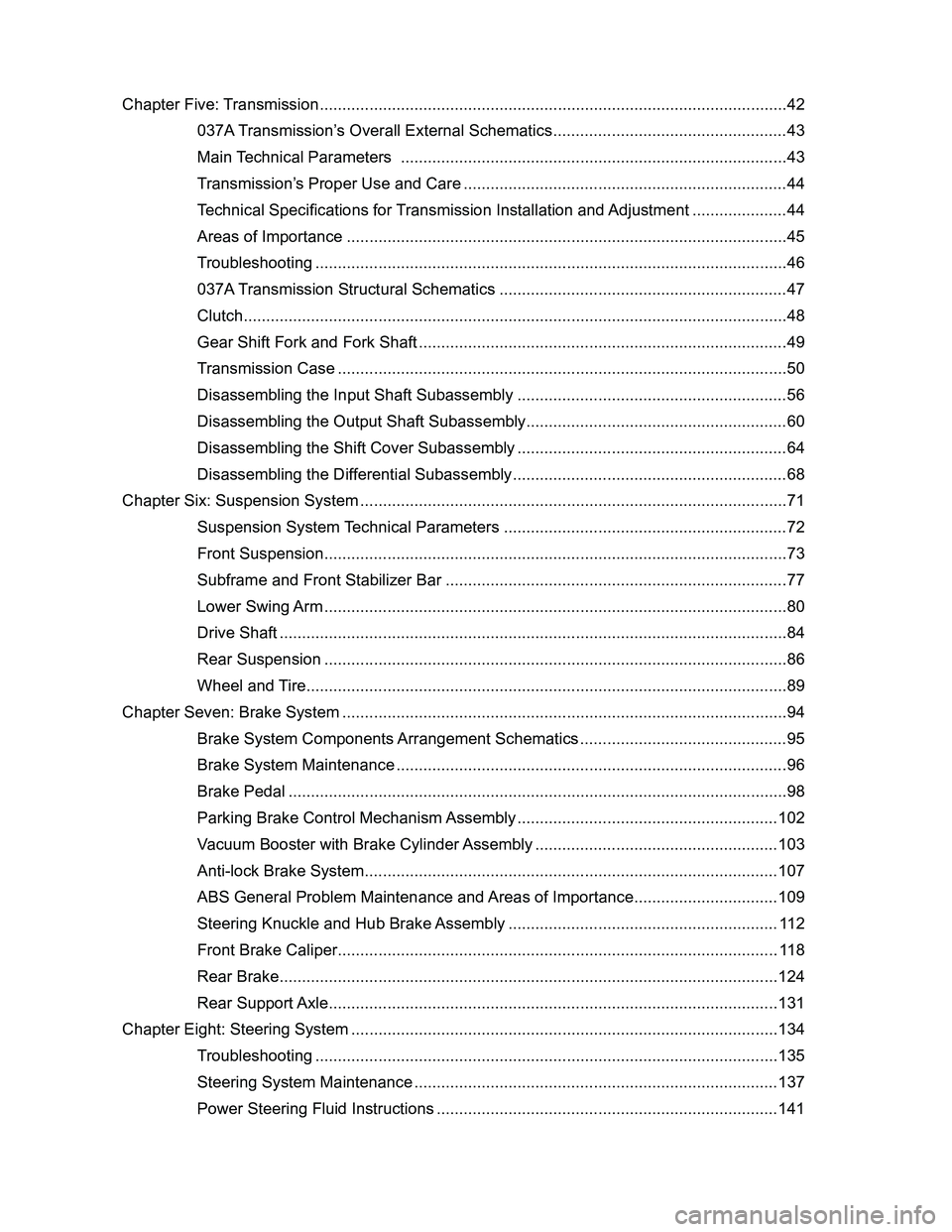
Downloaded from www.Manualslib.com manuals search engine Chapter Five: Transmission ........................................................................\
................................42
037A Transmission’s Overall External Schematics ....................................................43
Main Technical Parameters ..................................................................................\
....43
Transmission’s Proper Use and Care ........................................................................44
Technical Specifications for Transmission Installation and Adjustment .....................44
Areas of Importance ..................................................................................\
................45
Troubleshooting ..................................................................................\
.......................46
037A Transmission Structural Schematics ................................................................47
Clutch ...................................................................................\
......................................48
Gear Shift Fork and Fork Shaft ..................................................................................49
Transmission Case ..................................................................................\
..................50
Disassembling the Input Shaft Subassembly ............................................................56
Disassembling the Output Shaft Subassembly ..........................................................60
Disassembling the Shift Cover Subassembly ............................................................64
Disassembling the Differential Subassembly .............................................................68
Chapter Six: Suspension System ........................................................................\
.......................71
Suspension System Technical Parameters ...............................................................72
Front Suspension ...................................................................................\
....................73
Subframe and Front Stabilizer Bar ............................................................................77
Lower Swing Arm ...................................................................................\
....................80
Drive Shaft ..................................................................................\
...............................84
Rear Suspension ..................................................................................\
.....................86
Wheel and Tire ...................................................................................\
........................89
Chapter Seven: Brake System ........................................................................\
...........................94
Brake System Components Arrangement Schematics ..............................................95
Brake System Maintenance ...................................................................................\
....96
Brake Pedal ..................................................................................\
.............................98
Parking Brake Control Mechanism Assembly ..........................................................102
Vacuum Booster with Brake Cylinder Assembly ......................................................103
Anti-lock Brake System ...................................................................................\
.........107
ABS General Problem Maintenance and Areas of Importance ................................109
Steering Knuckle and Hub Brake Assembly ............................................................112
Front Brake Caliper ...................................................................................\
...............118
Rear Brake ...................................................................................\
............................124
Rear Support Axle ...................................................................................\
.................131
Chapter Eight: Steering System ........................................................................\
.......................134
Troubleshooting ..................................................................................\
.....................135
Steering System Maintenance .................................................................................137
Power Steering Fluid Instructions ............................................................................141
Page 6 of 281
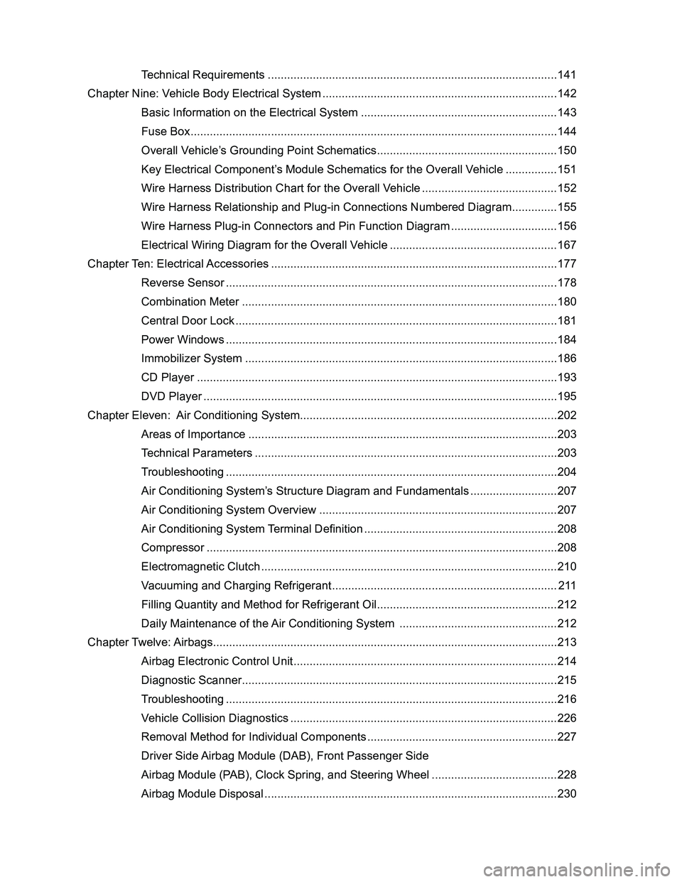
Downloaded from www.Manualslib.com manuals search engine Technical Requirements ..................................................................................\
........141
Chapter Nine: Vehicle Body Electrical System ........................................................................\
.142
Basic Information on the Electrical System .............................................................143
Fuse Box ...................................................................................\
...............................144
Overall Vehicle’s Grounding Point Schematics ........................................................150
Key Electrical Component’s Module Schematics for the Overall Vehicle ................151
Wire Harness Distribution Chart for the Overall Vehicle ..........................................152
Wire Harness Relationship and Plug-in Connections Numbered Diagram ..............155
Wire Harness Plug-in Connectors and Pin Function Diagram .................................156
Electrical Wiring Diagram for the Overall Vehicle ....................................................167
Chapter Ten: Electrical Accessories ........................................................................\
.................177
Reverse Sensor ..................................................................................\
.....................178
Combination Meter ..................................................................................\
................180
Central Door Lock ...................................................................................\
.................181
Power Windows ..................................................................................\
.....................184
Immobilizer System ..................................................................................\
...............186
CD Player ..................................................................................\
..............................193
DVD Player ..................................................................................\
............................195
Chapter Eleven: Air Conditioning System........................................................................\
........202
Areas of Importance ..................................................................................\
..............203
Technical Parameters ..................................................................................\
............203
Troubleshooting ..................................................................................\
.....................204
Air Conditioning System’s Structure Diagram and Fundamentals ...........................207
Air Conditioning System Overview ..........................................................................207
Air Conditioning System Terminal Definition ............................................................208
Compressor ..................................................................................\
...........................208
Electromagnetic Clutch ...................................................................................\
.........210
Vacuuming and Charging Refrigerant ......................................................................211
Filling Quantity and Method for Refrigerant Oil ........................................................212
Daily Maintenance of the Air Conditioning System .................................................212
Chapter Twelve: Airbags ........................................................................\
...................................213
Airbag Electronic Control Unit ..................................................................................214
Diagnostic Scanner ...................................................................................\
...............215
Troubleshooting ..................................................................................\
.....................216
Vehicle Collision Diagnostics ..................................................................................\
.226
Removal Method for Individual Components ...........................................................227
Driver Side Airbag Module (DAB), Front Passenger Side
Airbag Module (PAB), Clock Spring, and Steering Wheel .......................................228
Airbag Module Disposal ...................................................................................\
........230
Page 9 of 281
Downloaded from www.Manualslib.com manuals search engine GWFLORID Maintenance Manual2
How to Use This Manual
1. There is a content index on the first page of each
chapter. You can consult the index to see the items
needed for maintenance. In order to make searching
more convenient, the subject of each chapter has been
printed on the page header of each odd page.
2. There is a summary or caution item in the beginning of
each chapter. Please read this content carefully before
any maintenance is performed. Some systems include
a malfunction diagnostic table to help determine ve-
hicle failures and their causes.
3. Throughout the entire manual, each maintenance
step's corresponding specification is highlighted in bold,
so there should be no need to pause maintenance
work in order to find these specifications.
4. Warnings, Cautions & Notes
• Warnings are highlighted in bold, indicating the possibility
of causing injury to oneself or to others.
• Cautions are highlighted in bold, indicating the possibility
of damaging the part being repaired.
• Notes are listed separately from the instructions, not high-
lighted in bold. They are mainly used for additional expla-
nations in order to work more effectively.
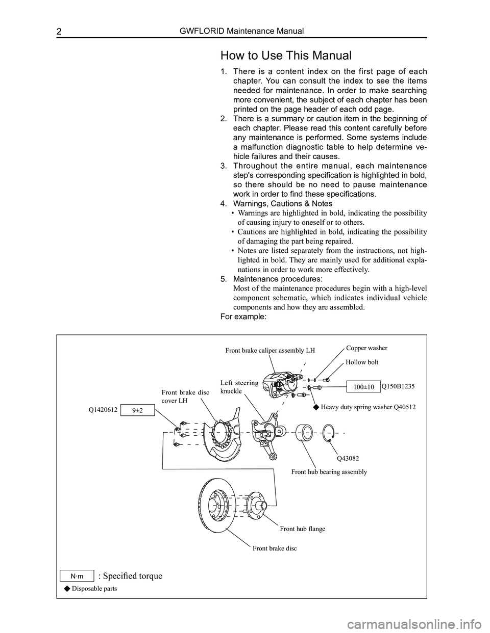
5. Maintenance procedures:
Most of the maintenance procedures begin with a high-level
component schematic, which indicates individual vehicle
components and how they are assembled.
For example:
Hollow bolt
Copper washer
Q150B1235
Heavy duty spring washer Q40512
Q43082
Front hub bearing assembly
Left steering
knuckleFront brake disc
cover LH
Q1420612
Front hub flange
Front brake disc
Front brake caliper assembly LH
100±10
9±2
N·m: Specified torque
Disposable parts
Page 21 of 281
Downloaded from www.Manualslib.com manuals search engine GWFLORID Maintenance Manual14
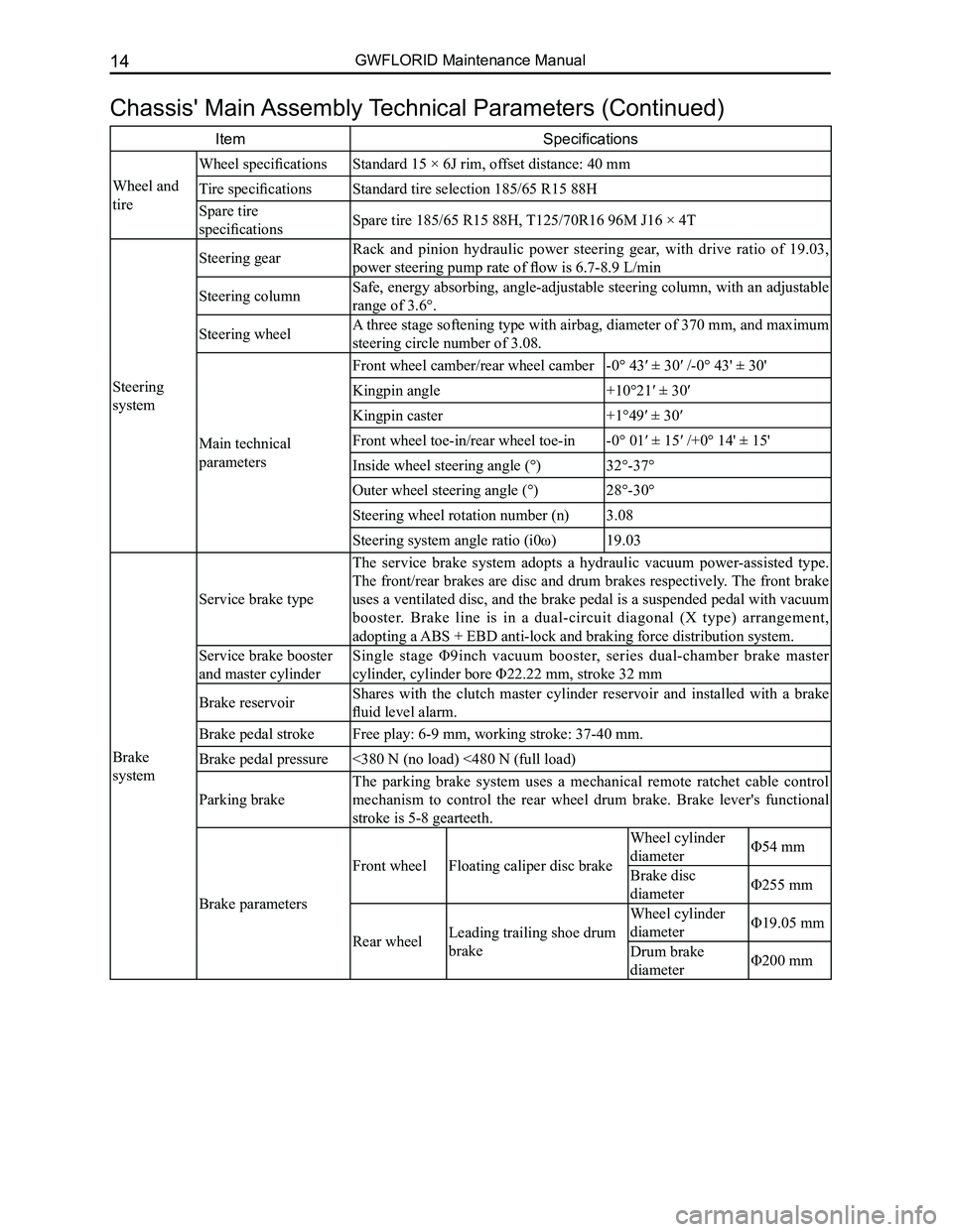
Chassis' Main Assembly Technical Parameters (Continued)
ItemSpecifications
Wheel and
tire
Wheel specificationsStandard 15 × 6J rim, offset distance: 40 mm
Tire specificationsStandard tire selection 185/65 R15 88H
Spare tire
specificationsSpare tire 185/65 R15 88H, T125/70R16 96M J16 × 4T
Steering
system
Steering gearRack and pinion hydraulic power steering gear, with drive ratio of 19.03,
power steering pump rate of flow is 6.7-8.9 L/min
Steering columnSafe, energy absorbing, angle-adjustable steering column, with an adjustable
range of 3.6°.
Steering wheelA three stage softening type with airbag, diameter of 370 mm, and maximum
steering circle number of 3.08.
Main technical
parameters
Front wheel camber/rear wheel camber-0° 43′ ± 30′ /-0° 43' ± 30'
Kingpin angle+10°21′ ± 30′
Kingpin caster+1°49′ ± 30′
Front wheel toe-in/rear wheel toe-in-0° 01′ ± 15′ /+0° 14' ± 15'
Inside wheel steering angle (°)32°-37°
Outer wheel steering angle (°)28°-30°
Steering wheel rotation number (n)3.08
Steering system angle ratio (i0ω)19.03
Brake
system
Service brake type
The service brake system adopts a hydraulic vacuum power-assisted type.
The front/rear brakes are disc and drum brakes respectively. The front brake
uses a ventilated disc, and the brake pedal is a suspended pedal with vacuum
booster. Brake line is in a dual-circuit diagonal (X type) arrangement,
adopting a ABS + EBD anti-lock and braking force distribution system.
Service brake booster
and master cylinder
Single stage Φ9inch vacuum booster, series dual-chamber brake master
cylinder, cylinder bore Φ22.22 mm, stroke 32 mm
Brake reservoirShares with the clutch master cylinder reservoir and installed with a brake
fluid level alarm.
Brake pedal strokeFree play: 6-9 mm, working stroke: 37-40 mm.
Brake pedal pressure<380 N (no load) <480 N (full load)
Parking brake
The parking brake system uses a mechanical remote ratchet cable control
mechanism to control the rear wheel drum brake. Brake lever's functional
stroke is 5-8 gearteeth.
Brake parameters
Front wheelFloating caliper disc brake
Wheel cylinder
diameterΦ54 mm
Brake disc
diameterΦ255 mm
Rear wheelLeading trailing shoe drum
brake
Wheel cylinder
diameterΦ19.05 mm
Drum brake
diameterΦ200 mm
Page 25 of 281
Downloaded from www.Manualslib.com manuals search engine GWFLORID Maintenance Manual18
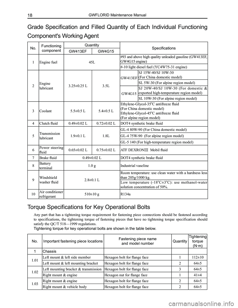
Torque Specifications for Key Operational Bolts
Any part that has a tightening torque requirement for fastening piece connections should be fastened according
to specifications, the tightening torque of fastening pieces that have no tightening torque specification should
satisfy the QC/T 518—1999 regulations.
Tightening torque for key operational bolts are shown in the table below.
No.Important fastening piece locationsFastening piece name
and model numberQuantity
Tightening
torque
(N·m)
1Chassis
1.01Left mount & left side memberHexagon bolt for flange face1112±10
Left mount & left mounting bracketHexagon bolt for flange face264±5
1.02Left mounting bracket & transmissionHexagon bolt for flange face364±5
Right mount & engineHexagon nut for flange face141±4
1.03Right mount & engineHexagon bolt for flange face264±5
Right mount & vehicle bodyHexagon bolt for flange face 264±5
Grade Specification and Filled Quantity of Each Individual Functioning
Component's Working Agent
No.Functioning
component
QuantitySpecificationsGW413EFGW4G15
1Engine fuel45L
#93 and above high quality unleaded gasoline (GW413EF,
GW4G15 engine)
#-10 light diesel fuel (YC4W75-31 engine)
2Engine
lubricant3.25±0.25 L3.5L
GW413EF
SJ 15W-40/SJ 10W-30
(For China domestic model)
SL 5W-30 (For alpine region model)
GW4G15
SJ 20W-40/SJ 10W-30 (For domestic &
exported high-temperature region model)
SL 10W-30 (For alpine region model)
3Coolant5.5±0.5 L5.4±0.5 L
Ethylene-Glycol-35oC antifreeze fluid
(For China domestic model)
Ethylene-Glycol-45oC antifreeze fluid
(For alpine region model)
4Clutch fluid0.49±0.02 L0.72±0.02 LDOT4 synthetic brake fluid
5Transmission
lubricant1.9±0.1 L1.8L
GL-4 80W-90 (For China domestic model)
GL-4 75W-90 (For alpine region model)
GL-5 140 (For high-temperature region model)
6Power steering
fluid0.65±0.02 L0.75±0.02 LATF DEXRONⅢ Mobil fluid
7Brake fluid0.49±0.02 LDOT4 synthetic brake fluid
8Battery
terminal1.0 gIndustrial vaseline
9Windshield
washer fluid2.8±0.1 L
Room temperature: use clean water with a hardness less
than 205g/1000 kg.
Low temperature (-18oC±3oC): use methanol-water
solution concentration of 50%.
10Air conditioner
refrigerant510±10 gR134a
Page 27 of 281
Downloaded from www.Manualslib.com manuals search engine GWFLORID Maintenance Manual20
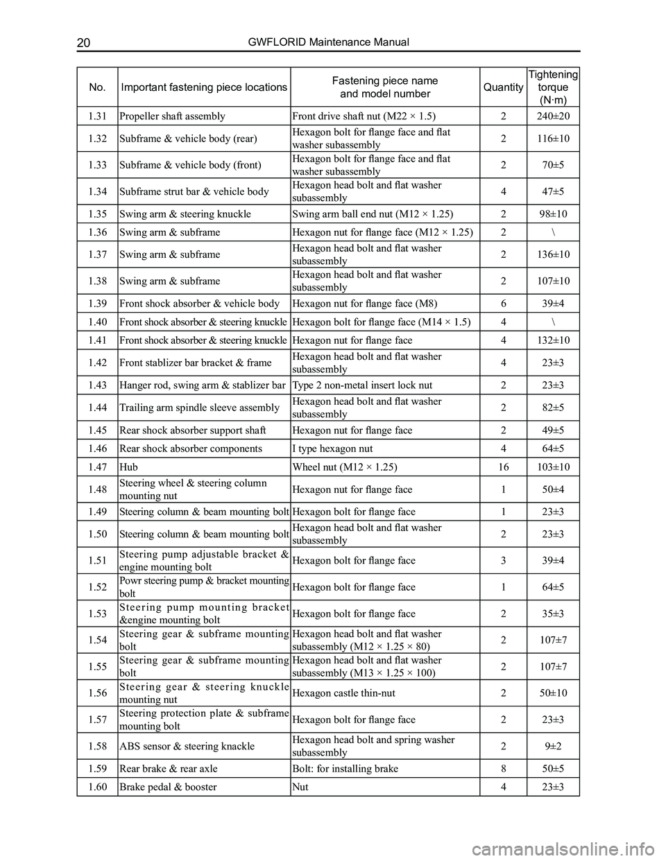
No.Important fastening piece locationsFastening piece name
and model numberQuantity
Tightening
torque
(N·m)
1.31Propeller shaft assemblyFront drive shaft nut (M22 × 1.5)2240±20
1.32Subframe & vehicle body (rear)Hexagon bolt for flange face and flat
washer subassembly2116±10
1.33Subframe & vehicle body (front)Hexagon bolt for flange face and flat
washer subassembly270±5
1.34Subframe strut bar & vehicle bodyHexagon head bolt and flat washer
subassembly447±5
1.35Swing arm & steering knuckleSwing arm ball end nut (M12 × 1.25)298±10
1.36Swing arm & subframeHexagon nut for flange face (M12 × 1.25)2\
1.37Swing arm & subframeHexagon head bolt and flat washer
subassembly2136±10
1.38Swing arm & subframeHexagon head bolt and flat washer
subassembly2107±10
1.39Front shock absorber & vehicle bodyHexagon nut for flange face (M8)639±4
1.40Front shock absorber & steering knuckleHexagon bolt for flange face (M14 × 1.5)4\
1.41Front shock absorber & steering knuckleHexagon nut for flange face4132±10
1.42Front stablizer bar bracket & frameHexagon head bolt and flat washer
subassembly423±3
1.43Hanger rod, swing arm & stablizer barType 2 non-metal insert lock nut223±3
1.44Trailing arm spindle sleeve assemblyHexagon head bolt and flat washer
subassembly282±5
1.45Rear shock absorber support shaftHexagon nut for flange face249±5
1.46Rear shock absorber componentsI type hexagon nut464±5
1.47Hub Wheel nut (M12 × 1.25)16103±10
1.48Steering wheel & steering column
mounting nutHexagon nut for flange face150±4
1.49Steering column & beam mounting boltHexagon bolt for flange face123±3
1.50Steering column & beam mounting boltHexagon head bolt and flat washer
subassembly223±3
1.51Steering pump adjustable bracket &
engine mounting boltHexagon bolt for flange face339±4
1.52Powr steering pump & bracket mounting
boltHexagon bolt for flange face164±5
1.53S t e e r i n g p u m p m o u n t i n g b r a c k e t
&engine mounting boltHexagon bolt for flange face235±3
1.54Steering gear & subframe mounting
bolt
Hexagon head bolt and flat washer
subassembly (M12 × 1.25 × 80)2107±7
1.55Steering gear & subframe mounting
bolt
Hexagon head bolt and flat washer
subassembly (M13 × 1.25 × 100)2107±7
1.56S t e e r i n g g e a r & s t e e r i n g k n u c k l e
mounting nutHexagon castle thin-nut250±10
1.57Steering protection plate & subframe
mounting boltHexagon bolt for flange face223±3
1.58ABS sensor & steering knackleHexagon head bolt and spring washer
subassembly29±2
1.59Rear brake & rear axleBolt: for installing brake850±5
1.60Brake pedal & boosterNut423±3
Page 79 of 281
Downloaded from www.Manualslib.com manuals search engine GWFLORID Maintenance Manual72
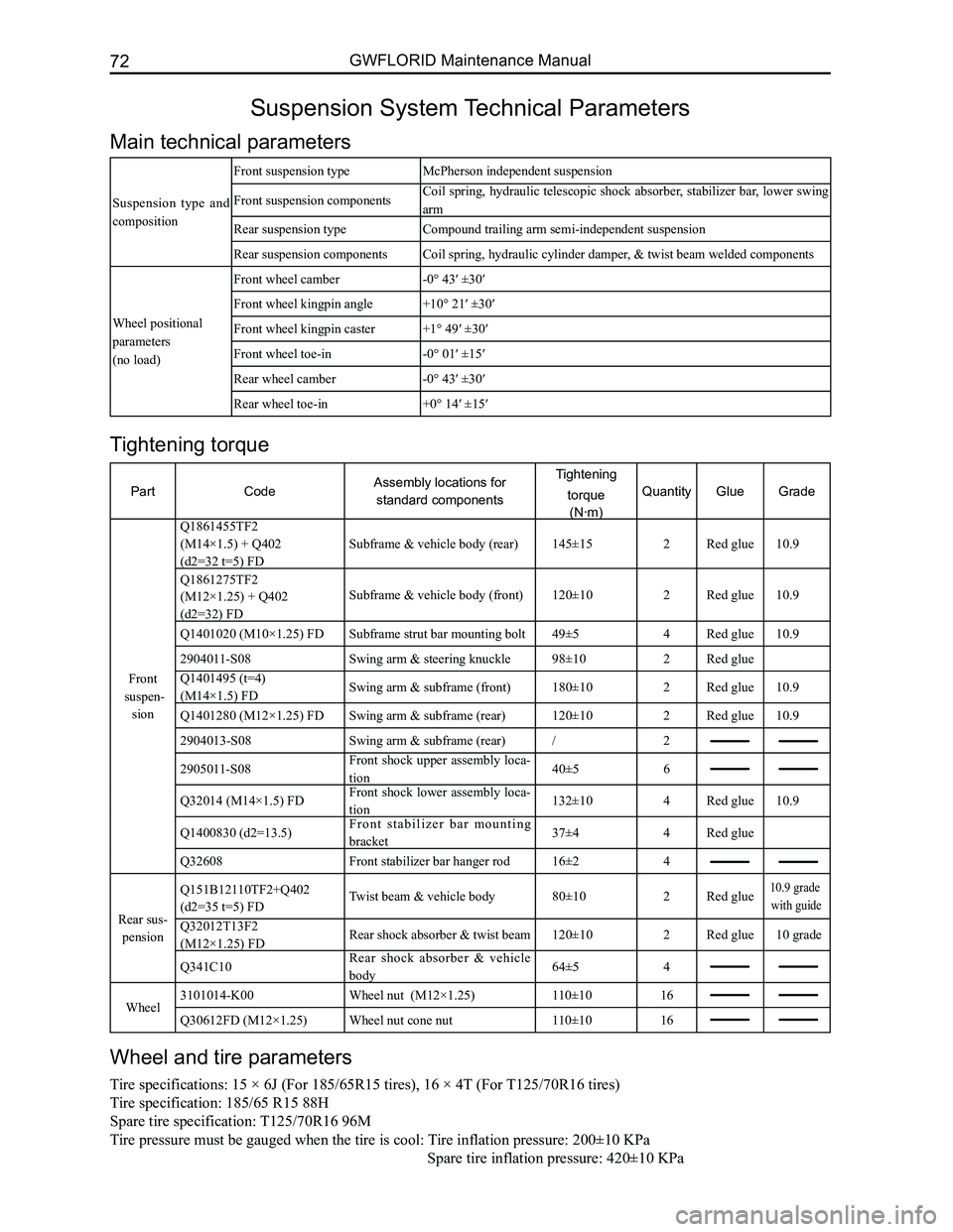
Suspension System Technical Parameters
Main technical parameters
Suspension type and
composition
Front suspension typeMcPherson independent suspension
Front suspension componentsCoil spring, hydraulic telescopic shock absorber, stabilizer bar, lower swing
arm
Rear suspension typeCompound trailing arm semi-independent suspension
Rear suspension componentsCoil spring, hydraulic cylinder damper, & twist beam welded components
Wheel positional
parameters
(no load)
Front wheel camber-0° 43′ ±30′
Front wheel kingpin angle+10° 21′ ±30′
Front wheel kingpin caster+1° 49′ ±30′
Front wheel toe-in-0° 01′ ±15′
Rear wheel camber-0° 43′ ±30′
Rear wheel toe-in+0° 14′ ±15′
Wheel and tire parameters
Tire specifications: 15 × 6J (For 185/65R15 tires), 16 × 4T (For T125/70R16 tires)
Tire specification: 185/65 R15 88H
Spare tire specification: T125/70R16 96M
Tire pressure must be gauged when the tire is cool: Tire inflation pressure: 200±10 KPa
Spare tir e inflation pressure: 420±10 KPa
Tightening torque
PartCodeAssembly locations for
standard components
Tightening
torque
(N·m)
QuantityGlueGrade
Front
suspen-
sion
Q1861455TF2
(M14×1.5) + Q402
(d2=32 t=5) FD
Subframe & vehicle body (rear)145±15 2Red glue10.9
Q1861275TF2
(M12×1.25) + Q402
(d2=32) FD
Subframe & vehicle body (front)120±102Red glue10.9
Q1401020 (M10×1.25) FDSubframe strut bar mounting bolt49±54Red glue10.9
2904011-S08Swing arm & steering knuckle98±102Red glue
Q1401495 (t=4)
(M14×1.5) FDSwing arm & subframe (front)180±102Red glue10.9
Q1401280 (M12×1.25) FDSwing arm & subframe (rear)120±102Red glue10.9
2904013-S08Swing arm & subframe (rear)/2
2905011-S08Front shock upper assembly loca-
tion40±56
Q32014 (M14×1.5) FDFront shock lower assembly loca-
tion132±104Red glue10.9
Q1400830 (d2=13.5)F r o n t s t a b i l i z e r b a r m o u n t i n g
bracket37±44Red glue
Q32608Front stabilizer bar hanger rod16±24
Rear sus-
pension
Q151B12110TF2+Q402
(d2=35 t=5) FDTwist beam & vehicle body80±102Red glue10.9 grade
with guide
Q32012T13F2
(M12×1.25) FDRear shock absorber & twist beam120±102Red glue10 grade
Q341C10Rear shock absorber & vehicle
body64±54
Wheel3101014-K00Wheel nut (M12×1.25)110±1016
Q30612FD (M12×1.25)Wheel nut cone nut110±1016
Page 80 of 281
Downloaded from www.Manualslib.com manuals search engine 73Suspension System
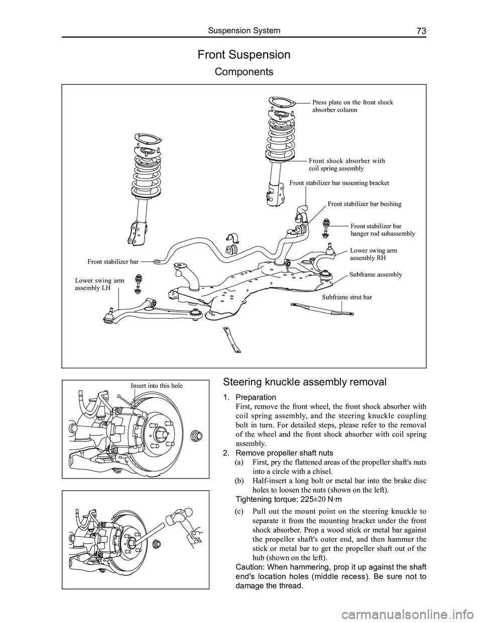
Steering knuckle assembly removal
1. Preparation
First, remove the front wheel, the front shock absorber with
coil spring assembly, and the steering knuckle coupling
bolt in turn. For detailed steps, please refer to the removal
of the wheel and the front shock absorber with coil spring
assembly.
2. Remove propeller shaft nuts
(a) First, pry the flattened areas of the propeller shaft's nuts
into a circle with a chisel.
(b) Half-insert a long bolt or metal bar into the brake disc
holes to loosen the nuts (shown on the left).
Tightening torque: 225±20 N·m
Front Suspension
Components
(c) Pull out the mount point on the steering knuckle to
separate it from the mounting bracket under the front
shock absorber. Prop a wood stick or metal bar against
the propeller shaft's outer end, and then hammer the
stick or metal bar to get the propeller shaft out of the
hub (shown on the left).
Caution: When hammering, prop it up against the shaft
end's location holes (middle recess). Be sure not to
damage the thread.
Insert into this hole
Press plate on the front shock absorber column
Front shock absorber with coil spring assembly
Front stabilizer bar mounting bracket
Front stabilizer bar bushing
Front stabilizer bar
Lower swing arm assembly RH
Lower swing arm assembly LH
Subframe assembly
Front stabilizer bar hanger rod subassembly
Subframe strut bar
Page 81 of 281
Downloaded from www.Manualslib.com manuals search engine GWFLORID Maintenance Manual74
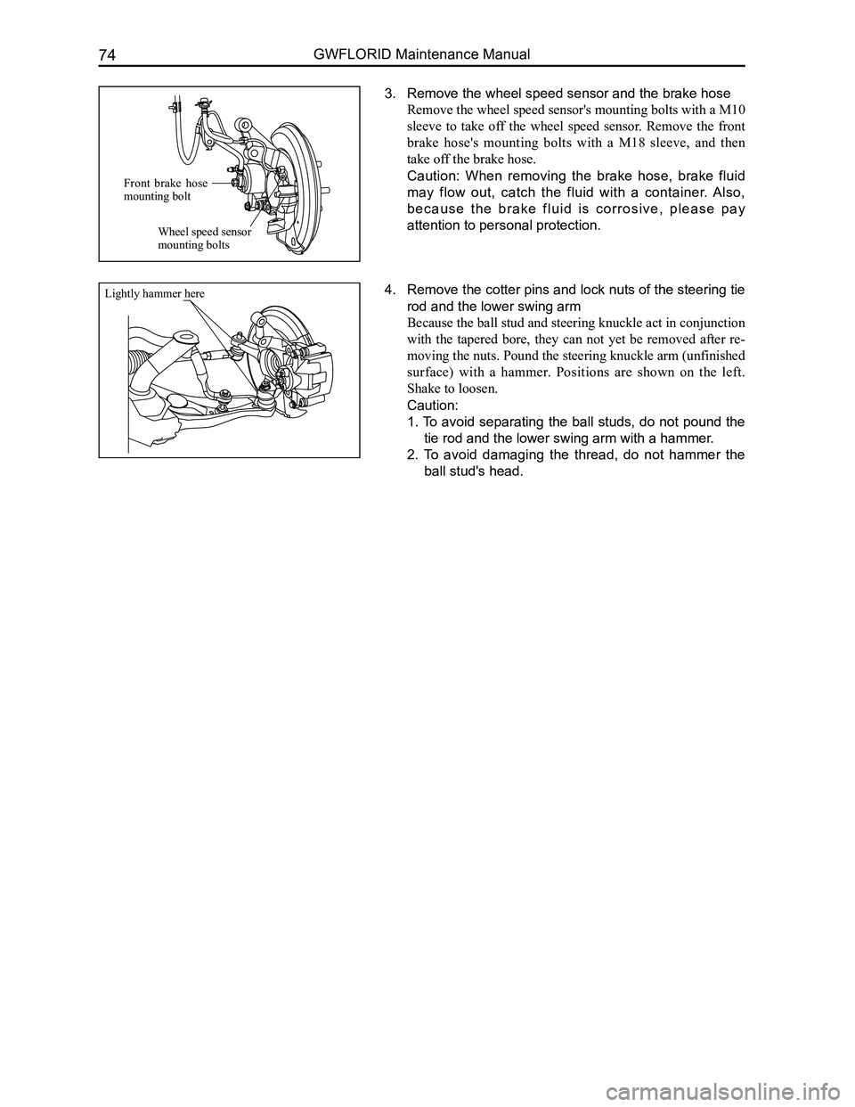
3. Remove the wheel speed sensor and the brake hose
Remove the wheel speed sensor's mounting bolts with a M10
sleeve to take off the wheel speed sensor. Remove the front
brake hose's mounting bolts with a M18 sleeve, and then
take off the brake hose.
Caution: When removing the brake hose, brake fluid
may flow out, catch the fluid with a container. Also,
b e c a u s e t h e b r a k e f l u i d i s c o r r o s i v e , p l e a s e p a y
attention to personal protection.
4. Remove the cotter pins and lock nuts of the steering tie
rod and the lower swing arm
Because the ball stud and steering knuckle act in conjunction
with the tapered bore, they can not yet be removed after re-
moving the nuts. Pound the steering knuckle arm (unfinished
surface) with a hammer. Positions are shown on the left.
Shake to loosen.
Caution:
1. To avoid separating the ball studs, do not pound the
tie rod and the lower swing arm with a hammer.
2. To avoid damaging the thread, do not hammer the
ball stud's head.
Front brake hose mounting bolt
Wheel speed sensor mounting bolts
Lightly hammer here
Page 82 of 281
Downloaded from www.Manualslib.com manuals search engine 75Suspension System
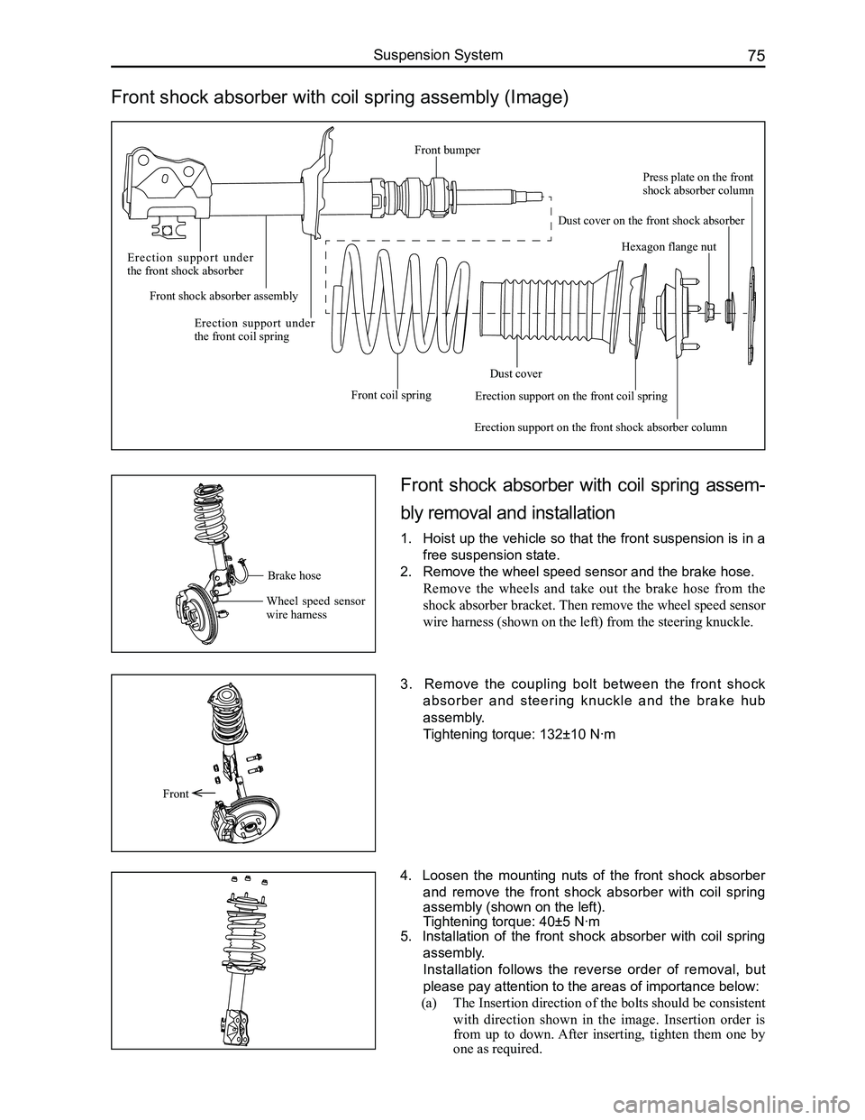
Front shock absorber with coil spring assembly (Image)
Front shock absorber with coil spring assem-
bly removal and installation
1. Hoist up the vehicle so that the front suspension is in a
free suspension state.
2. Remove the wheel speed sensor and the brake hose.
Remove the wheels and take out the brake hose from the
shock absorber bracket. Then remove the wheel speed sensor
wire harness (shown on the left) from the steering knuckle.
3. Remove the coupling bolt between the front shock
absorber and steering knuckle and the brake hub
assembly.
Tightening torque: 132±10 N·m
4. Loosen the mounting nuts of the front shock absorber
and remove the front shock absorber with coil spring
assembly (shown on the left).
Tightening torque: 40±5 N·m
5. Installation of the front shock absorber with coil spring
assembly.
Installation follows the reverse order of removal, but
please pay attention to the areas of importance below:
(a) The Insertion direction of the bolts should be consistent
with direction shown in the image. Insertion order is
from up to down. After inserting, tighten them one by
one as required.
Front
Brake hose
Wheel speed sensor wire harness
E r e c t i o n s u p p o r t u n d e r the front shock absorber
Front shock absorber assembly
Erection support under the front coil spring
Front coil spring
Dust cover
Erection support on the front shock absorber column
Hexagon flange nut
Press plate on the front shock absorber column
Dust cover on the front shock absorber
Erection support on the front coil spring
Front bumper