light GREAT WALL HOVER 2006 Service Owner's Manual
[x] Cancel search | Manufacturer: GREAT WALL, Model Year: 2006, Model line: HOVER, Model: GREAT WALL HOVER 2006Pages: 425, PDF Size: 26.05 MB
Page 314 of 425
Brake-28
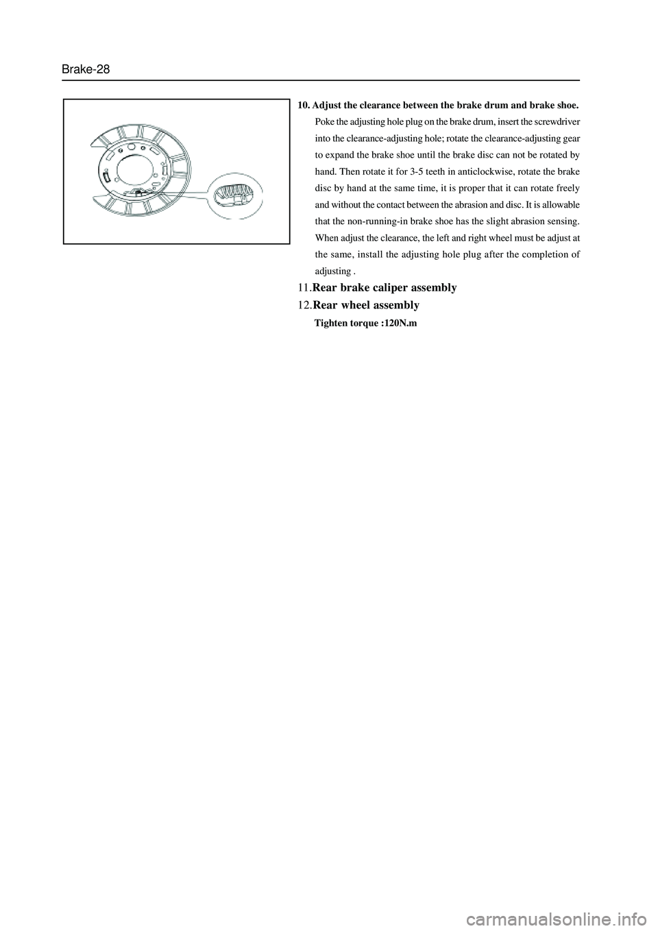
10. Adjust the clearance between the brake drum and brake shoe.
Poke the adjusting hole plug on the brake drum, insert the screwdriver
into the clearance-adjusting hole; rotate the clearance-adjusting gear
to expand the brake shoe until the brake disc can not be rotated by
hand. Then rotate it for 3-5 teeth in anticlockwise, rotate the brake
disc by hand at the same time, it is proper that it can rotate freely
and without the contact between the abrasion and disc. It is allowable
that the non-running-in brake shoe has the slight abrasion sensing.
When adjust the clearance, the left and right wheel must be adjust at
the same, install the adjusting hole plug after the completion of
adjusting .
11.Rear brake caliper assembly
12.Rear wheel assembly
Tighten torque :120N.m
Page 317 of 425
Brake-31
Antilock Braking System (ABS)
Cautions
1. It must not remove or install the electric elements and wire bunch plug when the ignition switch is in ON to avoid
the damage of ECU. It should turn off the ignition switch if needs disassembly.
2. Pay attention to do not knock or impact the ABS ECU during the maintenance and repair, for it will damage the
ABS ECU easily.
3. The wheel speed sensor and hydraulic unit (integrated with ECU) of BOSCH ABS8.0 can not be repaired, it should
be replaced in integral if damaged.
4. After the brake system is maintained, the brake pedal maybe soft. Discharge the air according to the normal brake
system.
5. It must use the brake fluid from original manufacturer; the brake fluid of different number cannot be used in mixed,
otherwise it will cause the failure of brake system. Select the tyre of original type as most as possible
Repair of Antilock Braking System (ABS)
1. It should process the failure diagnosis for the brake system before process the ABS failure diagnosis. It can
diagnose out the failure rapidly by using Table 1. In Table 1, the small number means the failure which occurs most
possibly. Check each element according to the sequence and maintain or replace it if necessary.
2. Check the following elements for normal operation before the diagnosis:
Brake fluid level and brake fluid quality
Pressure of tyre, size of tyre, shape and depth of tyre figure
Other brake component
These components will affect the brake effect of the ABS. Check the system sensor, connecting wire and connector for correct
installation, arrangement and connection. Ensure the completeness of fuse, repair or replace it if necessary.
3. Process the analysis and diagnosis according to the ABS advanced by owner. Use the diagnosis instrument (Annex
1) for final check and confirmation. It must process the run inspection after the competition of all ABS maintenance.
The test condition is shown as follows:
a. Confirm the tyre complies with the requirement, the tyre pressure is normal.
b. The brake system (including brake light ) is normal
c. The brake system is without leakage.
d. The position and installation of wheel speed sensor is correct.
e. All fuses are normal.
4. test method:
Run for 1 min at least when the vehicle speed is beyond 40Km/h, process a proper brake. Then read out the failure code to
ensure the ABS is without failure code.
Page 328 of 425
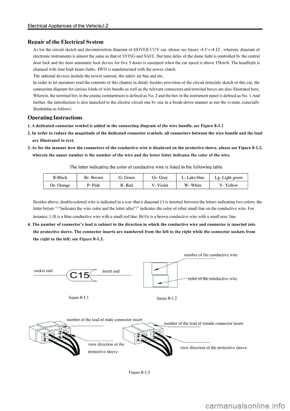
B-Black Br- Brown G- Green Gr- Gray L- Lake blue Lg- Light green
Or- Orange P- Pink R- Red V- Violet W- White Y- Yellow
Page 351 of 425
Controller of the Central Door Lock
1. Positive pole of the power supply (12V) is connected to the positive pole of car’s battery through a 15A fuse; when the
engine is started, the voltage is not less than 10V.
2. Output of the central door lock. The unlock cable connected to the executor of the central door lock is usuall
y grounded
through the normally-closed contact of the internal relay; when the door is unlocked by the remote controller or unlocked
manually, the public contact of the relay will get through with the normally-open contact, realizing an output of 12V
voltage.
3. Out
put of the central door lock. The lock cable connected to the executor of the central door lock is usually grounded
through the normally-closed contact of the internal relay; when the door is locked by the remote controller or locked
manually, the public contact of the relay will get through the normally-open contact, realizing an output of 12V voltage.
4. Key detection cable. This cable is connected to the ignition lock of the car and will
get through with the grounding wire
when the key is inserted into. (negative input)
5. Ri
ght direction indicator. The cable is connected to the positive pole of the right direction indicator of the car; an output of
12V voltage will be available when this cable is at work.
6. Left direction indicator. The cable is connected to the
positive pole of the right direction indicator of the car; an output of
12V voltage will be available when this cable is at work.
7. Negative input of door switch, which is connected to the door switch of the car; this cable will be earthed when the door is
opened. (Interior lights will be on)
a. Open the door and then close it, the reading light will be on for 10 seconds; if during this period, it is detected that the key has
been inserted into the ignition lock or the door closed, then the reading light will turn off.
b. When the key is pulled out of the ignition lock, then reading light will turn on, during this period, if the key is reinserted into
the ignition lock or the door lock, the reading light will be off; if there is not any action when the door is closed within 1
minute, the reading light will automatically turn off.
8. ON power supply detection cable. A conductive wire connected to the ON gear of the ignition lock. (When the ke
y is turned
to the ON position, a 12V output will be available)
9. Car s
peedometer detection cable, which is connected to the detection cable of car's speedometer. (When the car is
accelerated to the speed of 15km/h, the instruments unit will out
put a 500mS rectangular positive pulse to the central door
lock controller, which will control the locking of the central door lock when this 500mS rectangular positive pulse signal is
detected by the controller.)
10. Output of window closing si
gnal. When the door is locked by the remote controller, this line will be available with an
output of 12V positive current for one second and then be off. (No output)
11. Locking signal. The locking signal line connected to the central door lock of car's left front door is connected throu
gh with
the grounding line when at work. (Earthing)
12. Unlockin
g signal. The unlocking signal line connected to the central door lock of car's left front door is connected through
with the grounding line when at work. (Earthing)
13. Ne
gative pole of the power supply, which is connected to the car body, (earthing) line shall be as short as possible,
over-length will produce the interference.
Function of controller of the central door lock
1. Locking. When all the car doors are closed, press LOCK button of the remote controller once, at this time, the direction
indicator will flash once and the central door lock is closed.
2. Unlocking. At the locking state, press UNLOCK button of the remote controller once, at this time, the direction indicato
r
will flash two times and the central door lock is opened.
3. Car-findin
g function. At the locking state, press LOCK bottom of the remote controller once, and at this time, the direction
indicator will flash ten times quickly. Press UNLOCK button of the remote controller to quit the car-finding function.
4. Automatic
prevention function. At the locking state, press UNLOCK button of the remote controller to open the lock; if the
Page 356 of 425
CD Player and Air Conditioning System-3
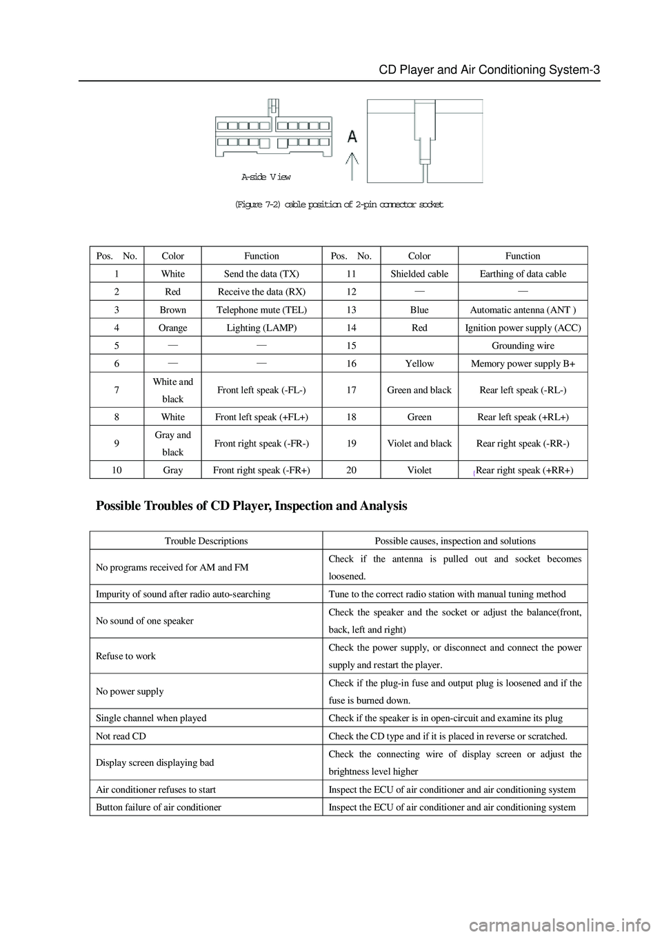
(Figure 7-2) cable position of 2-pin connector socket
Pos. No. Color Function Pos. No. Color Function
1 Whit e Send the data (TX) 11 Shielded cable Earthing of data cable
2 Red Receive the data (RX) 12 — —
3 Brown Telephone mute (TEL) 13 Blue Automatic antenna (ANT )
4 Orange Lighting (LAMP) 14 Red Ignition power supply (ACC)
5 — — 15 Grounding wire
6 — — 16 Yellow Memory power supply B+
7 Whit e and
black Front left speak (-FL-) 17 Green and black Rear left speak (-RL-)
8 White Front left speak (+FL+) 18 Green Rear left speak (+RL+)
9 Gray and
black Front right speak (-FR-) 19 Violet and black Rear right speak (-RR-)
10 Gray Front right speak (-FR+) 20 Violet {Rear right speak (+RR+)
Possible Troubles of CD Player, Inspection and Analysis
Trouble Descriptions Possible causes, inspection and solutions
No programs received for AM and FM Check if the antenna is pulled out and socket becomes
loosened.
Impurity of sound after radio auto-searching Tune to the correct radio station with manual tuning method
No sound of one speaker Check the speaker a nd the socket or adjust the balance(front,
back, left and right)
Refuse to work Check the power supply, or disconnect and connect the power
supply and restart the player.
No power supply Check if the plug-in fuse and output plug is loosened and if the
fuse is burned down.
Single channel when played Check if the speaker is in open-circuit and examine its plug
Not read CD Check the CD type and if it is placed in reverse or scratched.
Display screen displaying bad Check the connecting wire of display screen or adjust the
brightness level higher
Air conditioner refuses to start Inspect the ECU of air conditioner and air conditioning system
Button failure of air conditioner Inspect the ECU of air conditioner and air conditioning system
A-side V iew
Page 359 of 425
CD Player and Air Conditioning System-6
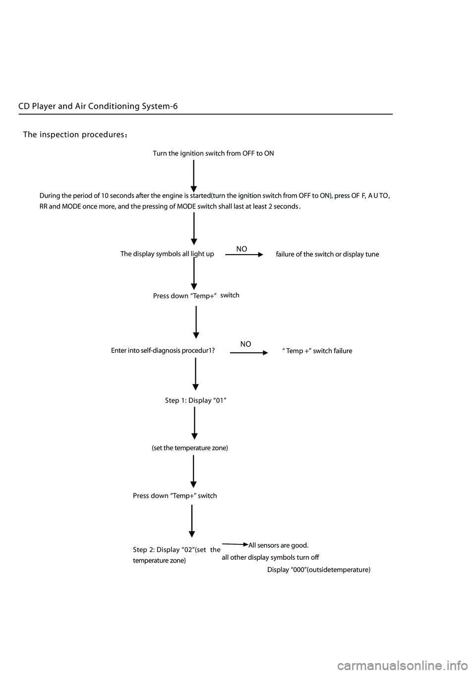
Turn the ignition switch from OFF to ON
The display symbols all light up
failure of the switch or display tune
NO
Press down “Temp+” switch
Enter into self-diagnosis procedur1?
NO“ Te mp +” switch failure
Step 1:
Display “01”
(set t he temperature zone)
all other display symbols turn of
f
Press
down
“Temp+” switch
Step 2: Display
“02”(set the
temperature
z one)
The inspection procedures
During the period of 10 seconds after the engine is started(turn the ignition switch from OFF to ON), press OF F, A U T O ,
RR and MODE once more, and the pressing of MODE switch shall last at least 2 seconds
.
A ll sensors are good.
Display
“000”(outsidetemperature)
Page 365 of 425
CD Player and Air Conditioning System-12
e .Precautions for the overhaul of air cooling system
When the air cooling system encounters the trouble, the cause for such trouble shall be analyzed inlightof trouble varieties,
followed with the examination and report work.
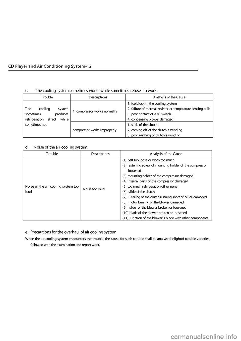
c. T he c ooling system some time s w orks wh ile some time s refus es towo rk.
T rou ble Des cri p tion s Ana l ysis o f the C ause
1.comp ress or wo rks n orma l l y 1.
ice b lock i nthe c ool i ng s yste
m
2. failu reof therma l resisto r o r tem perature sens ing b ul
b
3. poor contac t o f A /Cswitch
4. cond ensing blow erdama ge
d
T he c ooling system
so me time s p rodu ce
s
re f ri g eratio n e f f ect whil
e
so me time s not
.
comp resso r w orks i mprop erl y 1.s
lid e o f the clut ch
2. comi ng off o f the clut ch ’ s wind i n
g
3. poor earthi ng ofclut ch ’ s wind i n
g
d. N oise o f the air c oolin g s ystem
T r ou ble Des cription s Ana l ysis o f the C ause
No ise o f the air c ooling system too
lo ud N o
ise t oo l oud (1
) b elt t oo
loos e or w orn t oo mu ch
(2 ) f asteni ng screw o f mounting h olde r o f the comp resso
r
lo os en ed
(3 ) m ounti n g h olde r o f the comp resso r dam aged
(4 ) i nter na l p arts of the c om pr
esso r dam aged
(5 ) t oo mu chref ri g eratio n o ilor none
(6 ) .
slid e o f the clut ch
(7 ) . B e aring o f the clut ch runni ngshort o f o i lor dama ge
d
(8 ) . mo tor b earing ofthe b lowe r dam aged
(9 ) h olde r o f the blow erbrok en or
loos ened
(1 0) blad e o f the blow erbrok en or
loos ened
(1 1) . F rict io n o f the blow er’ s blad e w ith o ther comp onents
Page 375 of 425
Safety airbag-5
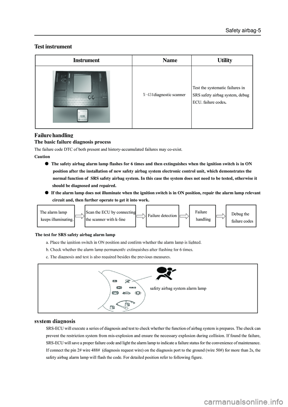
Test instrument
InstrumentNameUtility
diagnostic scanner
The alarm lamp
keeps illuminating.Failure
handlingDebug the
failure codes
Test the systematic failures in
SRS safety airbag system, debug
ECU. failure codes.
The basic failure diagnosis process
The failure code DTC of both present and history-accumulated failures may co-exist.
Caution
The safety airbag alarm lamp flashes for 6 times and then extinguishes when the ignition switch is in ON
position after the installation of new safety airbag system electronic control unit, which demonstrates the
normal function of SRS safety airbag system. In this case the system does not need to be tested, otherwise it
should be diagnosed and repaired.
If the alarm lamp does not illuminate when the ignition switch is in ON position, repair the alarm lamp relevant
circuit and, then further operate to get it into work.
Scan the ECU by connecting
the scanner with k-lineFailure detection
The test for SRS safety airbag alarm lamp
SRS-ECU will execute a series of diagnosis and test to check whether the function of airbag system is prepares. The check can
prevent the restriction system from mis-explosion and ensure the necessary explosion during collision. If found the failure,
SRS-ECU will save a proper failure code and light the alarm lamp to indicate a failure status for the convenience of maintenance.
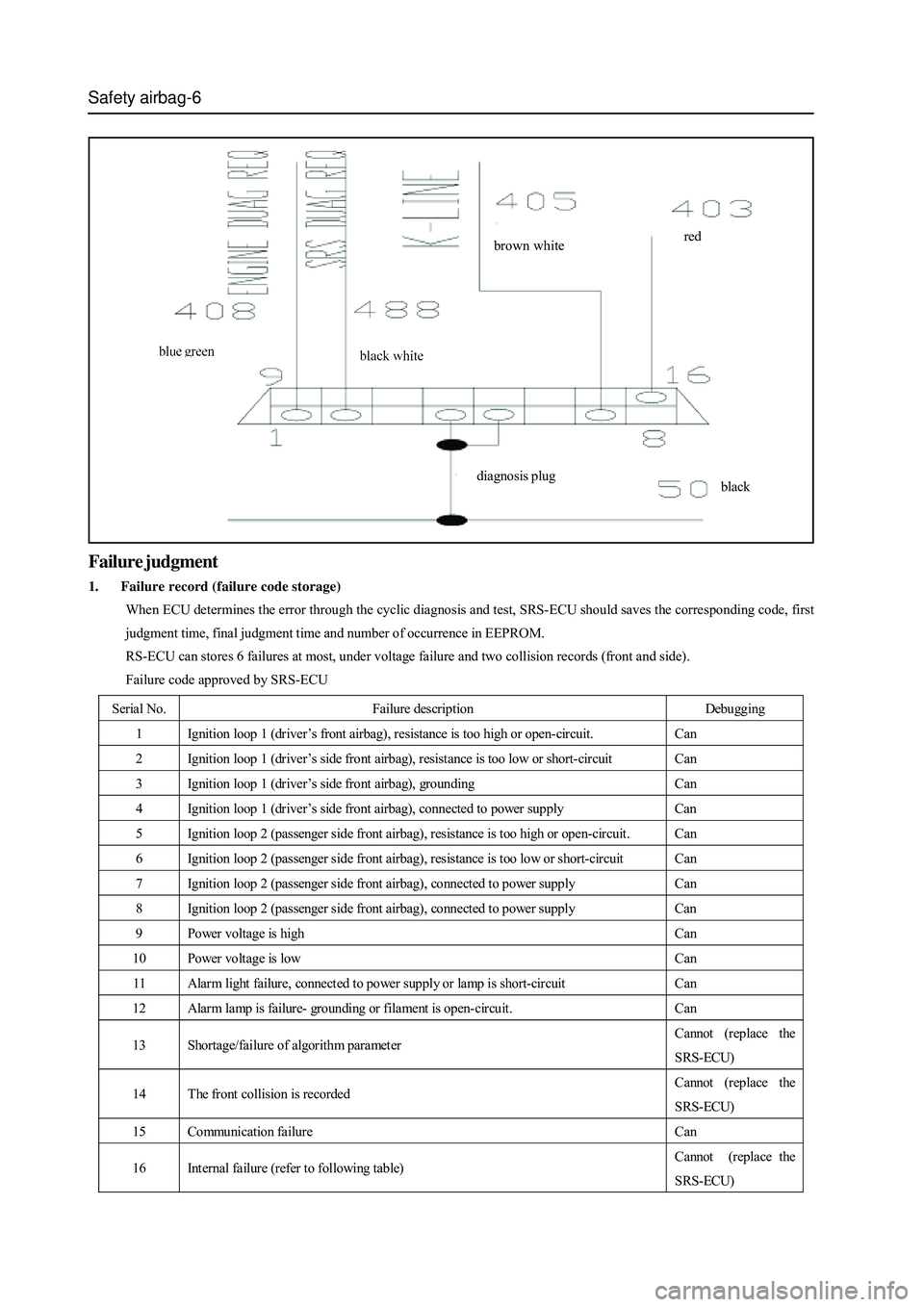
If connect the pin 2# wire 488# (diagnosis request wire) on the diagnosis port to the ground (wire 50#) for more than 2s, the
safety airbag alarm lamp will flash the code. For detailed position refer to following figure.safety airbag system alarm lamp
Page 376 of 425
Safety airbag-6
brown whitered
diagnosis plug
black
Failure judgment
1. Failure record (failure code storage)
When ECU determines the error through the cyclic diagnosis and test, SRS-ECU should saves the corresponding code, first
judgment time, final judgment time and number of occurrence in EEPROM.
RS-ECU can stores 6 failures at most, under voltage failure and two collision records (front and side).
Failure code approved by SRS-ECU
Serial No. Failure description Debugging
1 Ignition loop 1 (driver ’s front airbag), resistance is too high or open-circuit. Can
2 Ignition loop 1 (driver ’s side front airbag), resistance is too low or short-circuit Can
3 Ignition loop 1 (driver ’s side front airbag), grounding Can
4 Ignition loop 1 (driver’s side front airbag), connected to power supply Can
5 Ignition loop 2 (passenger side front airbag), resistance is too high or open-circuit. Can
6 Ignition loop 2 (passenger side front airbag), resistance is too low or short-circuit Can
7 Ignition loop 2 (passenger side front airbag), connect ed t o power supply Can
8 Ignition loop 2 (passenger side front airbag), connect ed t o power supply Can
9 Power voltage is high Can
10 Power voltage is low Can
11 Alarm light failure, connect ed to power supply or lamp is short-circuit Can
12 Alarm lamp is failure- grounding or filament is open-circuit. Can
13 Shortage/failure of algorithm parameter Cannot (replace the
SRS-ECU)
14 The front collision is recorded Cannot (replace the
SRS-ECU)
15 Communication failure Can
16 Internal failure (refer to following table) Cannot (replace the
SRS-ECU)
Page 377 of 425
Safety airbag-7
Description of flash code
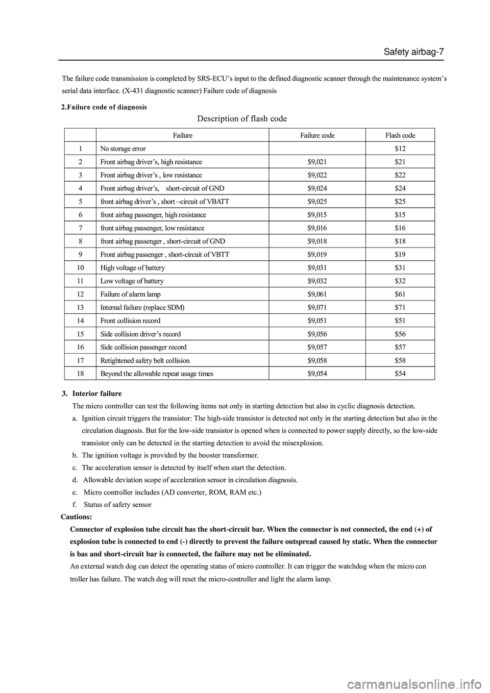
The failure code transmission is completed by SRS-ECU’s input to the defined diagnostic scanner through the maintenance system’s
serial data interface. (X-431 diagnostic scanner) Failure code of diagnosis
Failure Failure code Flash code
1 No storage error $12
2 Front airbag driver’s, high resistance $9,021 $21
3 Front airbag driver’s , low resistance $9,022 $22
4 Front airbag driver ’s, short-circuit of GND $9,024 $24
5 front airbag driver ’s , short –circuit of VBATT $9,025 $25
6 front airbag passenger, high resistance $9,015 $15
7 front airbag passenger, low resistance $9,016 $16
8 front airbag passenger , short-circuit of GND $9,018 $18
9 Front airbag passenger , short-circuit of VBTT $9,019 $19
10 High voltage of battery $9,031 $31
11 Low voltage of battery $9,032 $32
12 Failure of alarm lamp $9,061 $61
13 Internal failure (replace SDM) $9,071 $71
14 Front collision record $9,051 $51
15 Side collision driver’s record $9,056 $56
16 Side collision passenger record $9,057 $57
17 Retightened safety belt collision $9,058 $58
18 Beyond the allowable repeat usage times $9,054 $54
3. Interior failure
The micro controller can test the following items not only in starting detection but also in cyclic diagnosis detection.
a. Ignition circuit triggers the transistor: The high-side transistor is detected not only in the starting detection but also in the
circulation diagnosis. But for the low-side transistor is opened when is connected to power supply directly, so the low-side
transistor only can be detected in the starting detection to avoid the misexplosion.
b. The ignition voltage is provided by the booster transformer.
c. The acceleration sensor is detected by itself when start the detection.
d. Allowable deviation scope of acceleration sensor in circulation diagnosis.
e. Micro controller includes (AD converter, ROM, RAM etc.)
f. Status of safety sensor
Cautions:
Connector of explosion tube circuit has the short-circuit bar. When the connector is not connected, the end (+) of
explosion tube is connected to end (-) directly to prevent the failure outspread caused by static. When the connector
is bas and short-circuit bar is connected, the failure may not be eliminated.
An external watch dog can detect the operating status of micro controller. It can trigger the watchdog when the micro con
troller has failure. The watch dog will reset the micro-controller and light the alarm lamp.