light GREAT WALL HOVER 2006 Service User Guide
[x] Cancel search | Manufacturer: GREAT WALL, Model Year: 2006, Model line: HOVER, Model: GREAT WALL HOVER 2006Pages: 425, PDF Size: 26.05 MB
Page 82 of 425
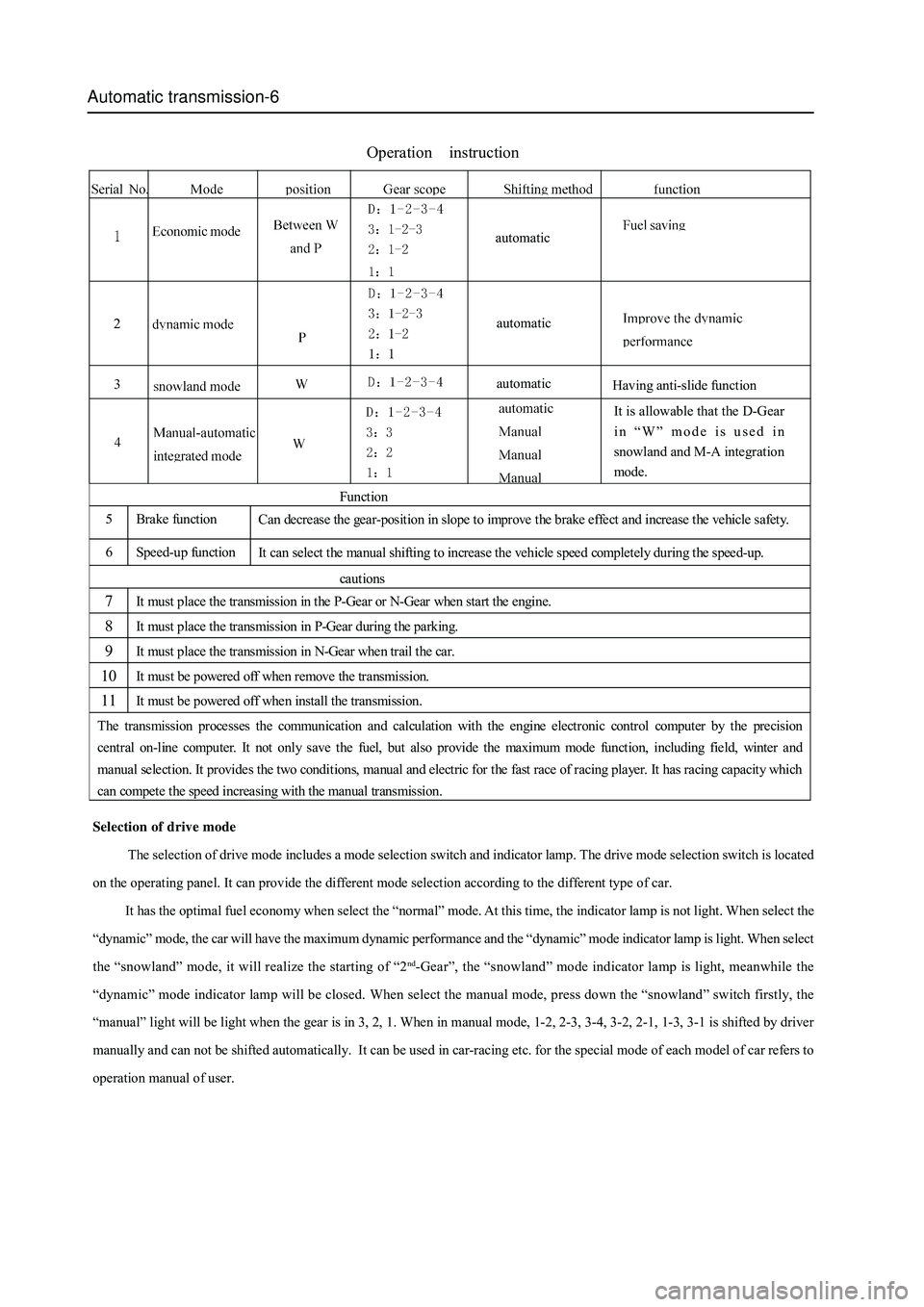
Automatic transmission-6
Selection of drive mode
The selection of drive mode includes a mode selection switch and indicator lamp. The drive mode selection switch is located
on the operating panel. It can provide the different mode selection according to the different type of car.
It has the optimal fuel economy when select the “normal” mode. At this time, the indicator lamp is not light. When select the
“dynamic” mode, the car will have the maximum dynamic performance and the “dynamic” mode indicator lamp is light. When select
the “snowland” mode, it will realize the starting of “2
nd-Gear”, the “snowland” mode indicator lamp is light, meanwhile the
“dynamic” mode indicator lamp will be closed. When select the manual mode, press down the “snowland” switch firstly, the
“manual” light will be light when the gear is in 3, 2, 1. When in manual mode, 1-2, 2-3, 3-4, 3-2, 2-1, 1-3, 3-1 is shifted by driver
manually and can not be shifted automatically. It can be used in car-racing etc. for the special mode of each model of car refers to
operation manual of user.
Operation instruction
Function
5 Brake function
Can decrease the gear-position in slope to improve the brake effect and increase the vehicle safety.
6 Speed-up function
It can select the manual shifting to increase the vehicle speed completely during the speed-up.
cautions
7 It must place the transmission in the P-Gear or N-Gear when start the engine.
8 It must place the transmission in P-Gear during the parking.
9 It must place the transmission in N-Gear when trail the car.
10 It must be powered off when remove the transmission.
11 It must be powered off when install the transmission.
The transmission processes the communication and calculation with the engine electronic control computer by the precision
central on-line computer. It not only save the fuel, but also provide the maximum mode function, including field, winter and
manual selection. It provides the two conditions, manual and electric for the fast race of racing player. It has racing capacity wh i ch
can compete the speed increasing with the manual transmission.
automatic
Having anti-slide function
It is allowable that the D-Gear
in “W” mode is used in
snowland and M-A integration
mode. automatic
automatic
Page 96 of 425
Automatic transmission-20
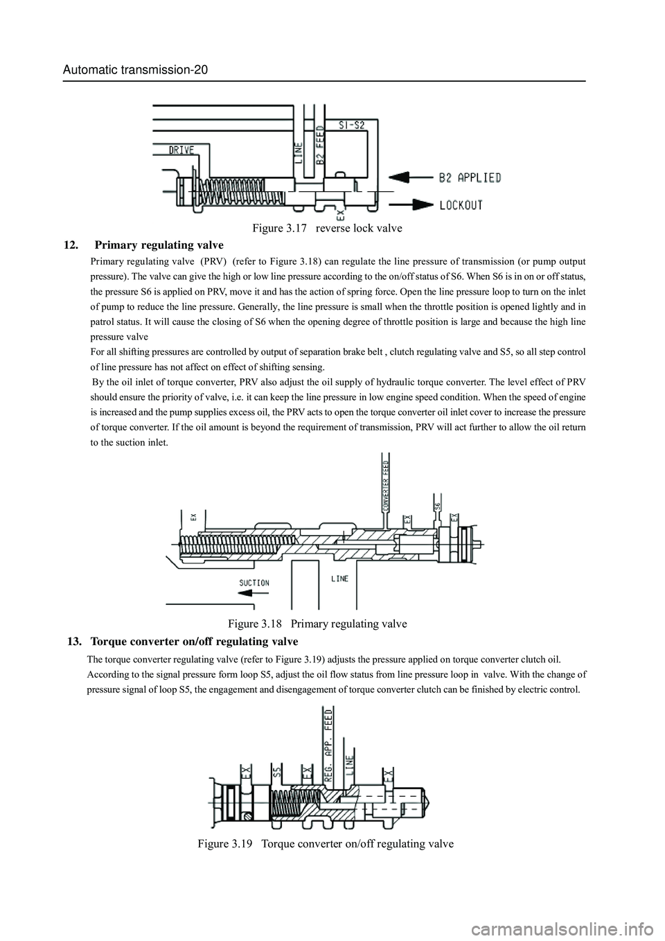
Figure 3.17 reverse lock valve
12. Primary regulating valve
Primary regulating valve (PRV) (refer to Figure 3.18) can regulate the line pressure of transmission (or pump output
pressure). The valve can give the high or low line pressure according to the on/off status of S6. When S6 is in on or off status,
the pressure S6 is applied on PRV, move it and has the action of spring force. Open the line pressure loop to turn on the inlet
of pump to reduce the line pressure. Generally, the line pressure is small when the throttle position is opened lightly and in
patrol status. It will cause the closing of S6 when the opening degree of throttle position is large and because the high line
pressure valve
For all shifting pressures are controlled by output of separation brake belt , clutch regulating valve and S5, so all step control
of line pressure has not affect on effect of shifting sensing.
By the oil inlet of torque converter, PRV also adjust the oil supply of hydraulic torque converter. The level effect of PRV
should ensure the priority of valve, i.e. it can keep the line pressure in low engine speed condition. When the speed of engine
is increased and the pump supplies excess oil, the PRV acts to open the torque converter oil inlet cover to increase the pressure
of torque converter. If the oil amount is beyond the requirement of transmission, PRV will act further to allow the oil return
to the suction inlet.
Figure 3.18 Primary regulating valve
Figure 3.19 Torque converter on/off regulating valve
The torque converter regulating valve (refer to Figure 3.19) adjusts the pressure applied on torque converter clutch oil.
According to the signal pressure form loop S5, adjust the oil flow status from line pressure loop in valve. With the change of
pressure signal of loop S5, the engagement and disengagement of torque converter clutch can be finished by electric control.
13. Torque converter on/off regulating valve
Page 130 of 425
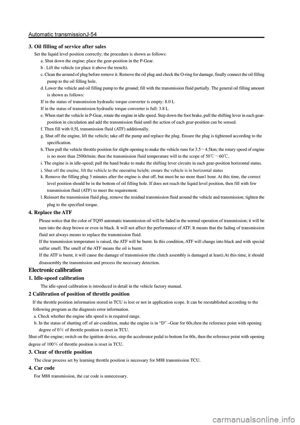
3. Oil filling of service after sales
Set the liquid level position correctly; the procedure is shown as follows:
a. Shut down the engine; place the gear-position in the P-Gear.
b . Lift the vehicle (or place it above the trench).
c. Clean the around of plug before remove it. Remove the oil plug and check the O-ring for damage, finally connect the oil filling
pump to the oil filling hole.
d. Lower the vehicle and oil filling pump to the ground; fill with the transmission fluid partially. The general oil filling amount
is shown as follows:
If in the status of transmission hydraulic torque converter is empty: 8.0 L
If in the status of transmission hydraulic torque converter is full: 3.8 L
e. When start the vehicle in P-Gear, rotate the engine in idle speed. Step down the foot brake, pull the shifting lever in each gear-
position in circulation and add the transmission fluid until the action of each gear-position can be sensed.
f. Then fill with 0.5L transmission fluid (ATF) additionally.
g. Shut off the engine, lift the vehicle; take off the pump and replace the plug. Ensure the plug is tightened according to the
specification.
h. Then pull the vehicle throttle position for slight opening to make the vehicle runs for 3.5
4.5km; the rotary speed of engine
is no more than 2500r/min; then the transmission fluid temperature will in the scope of 50
60.
i. The engine is in idle-speed; pull the hand brake to make the shifting lever circuits in each gear-position horizontal status.
k. Remove the filling plug 3 minutes after the engine is shut off, but must be no more than1 hour. At this time, the correct
level position should be in the bottom of oil filling hole. If does not reach the liquid level position, then fill with few
transmission fluid (ATF) to meet the requirement.
l. Reinsert the transmission fluid plug, remove the residual transmission fluid around the vehicle and transmission; tighten the
plug to the specified torque.
4. Replace the ATF
Please notice that the color of TQ95 automatic transmission oil will be faded in the normal operation of transmission; it will be
turn into the deep brown or even in black. It will not affect the performance of ATF. It means that the fading of transmission
fluid not always means to replace the transmission fluid.
If the transmission temperature is raised, the ATF will be burnt. In this condition, ATF will change into black and with special
sulfur smell. The smell of the ATF means the oil is burnt.
If the ATF is burnt, it will cause the damage of transmission (the clutch assembly is damaged at least).At this time, it should
disassembly the transmission and process the necessary detection.
Electronic calibration
1. Idle-speed calibration
The idle-speed calibration is introduced in detail in the vehicle factory manual.
2 Calibration of position of throttle position
If the throttle position information stored in TCU is lost or not in application scope. It can be reestablished according to the
following program as the diagnosis error information.
a. Check whether the engine idle speed is in required range.
b. In the status of shutting off of air-condition, make the engine is in “D” –Gear for 60s,then the reference point with opening
degree of 0
of throttle position is reset in TCU.
Shut off the engine; switch on the ignition device, step the accelerator pedal to bottom for 60s, then the reference point with opening
degree of 100
of throttle position is reset in TCU.
3. Clear of throttle position
The clear process set by learning throttle position is necessary for M88 transmission TCU.
4. Car code
For M88 transmission, the car code is unnecessary.
Page 183 of 425
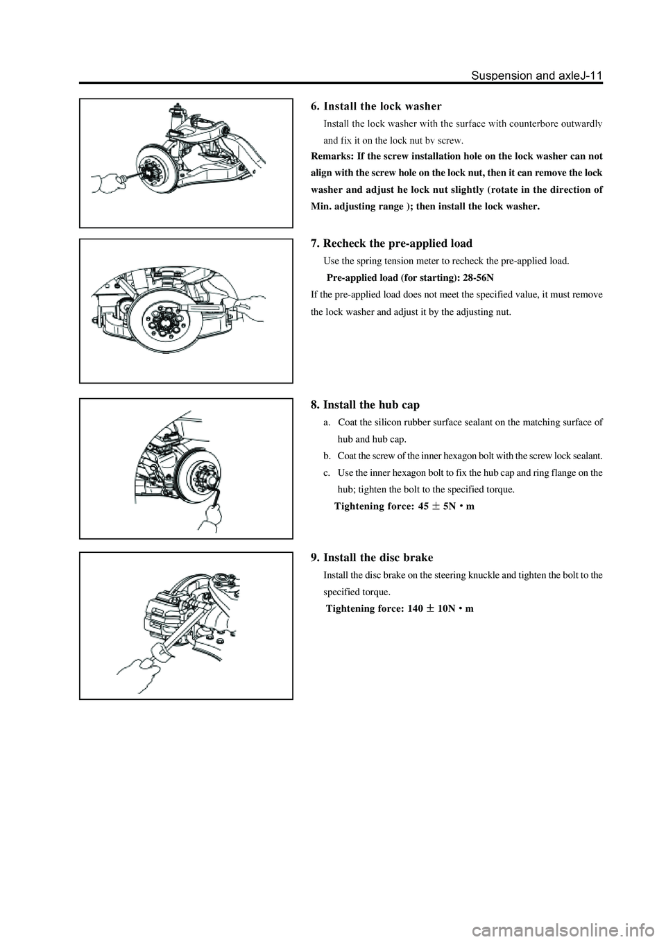
Remarks: If the screw installation hole on the lock washer can not
align with the screw hole on the lock nut, then it can remove the lock
washer and adjust he lock nut slightly (rotate in the direction of
Min. adjusting range ); then install the lock washer.
7. Recheck the pre-applied load
Use the spring tension meter to recheck the pre-applied load.
Pre-applied load (for starting): 28-56N
If the pre-applied load does not meet the specified value, it must remove
the lock washer and adjust it by the adjusting nut.
8. Install the hub cap
a. Coat the silicon rubber surface sealant on the matching surface of
hub and hub cap.
b. Coat the screw of the inner hexagon bolt with the screw lock sealant.
c. Use the inner hexagon bolt to fix the hub cap and ring flange on the
hub; tighten the bolt to the specified torque.
Tightening force: 45
5Nm
9. Install the disc brake
Install the disc brake on the steering knuckle and tighten the bolt to the
specified torque.
Tightening force: 140
10Nm
Page 205 of 425
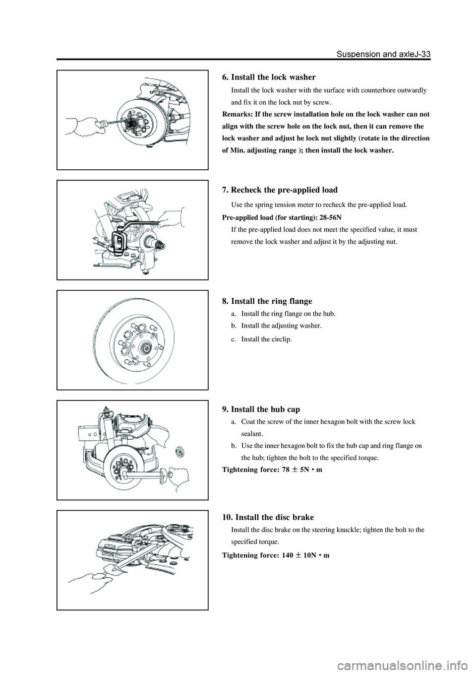
6. Install the lock washer
Install the lock washer with the surface with counterbore outwardly
and fix it on the lock nut by screw.
Remarks: If the screw installation hole on the lock washer can not
align with the screw hole on the lock nut, then it can remove the
lock washer and adjust he lock nut slightly (rotate in the direction
of Min. adjusting range ); then install the lock washer.
7. Recheck the pre-applied load
Use the spring tension meter to recheck the pre-applied load
Pre-applied load (for starting): 28-56N
If the pre-applied load does not meet the specified value, it must
remove the lock washer and adjust it by the adjusting nut.
8. Install the ring flange
a. Install the ring flange on the hub.
b. Install the adjusting washer.
c. Install the circlip.
9. Install the hub cap
a. Coat the screw of the inner hexagon bolt with the screw lock
sealant.
b. Use the inner hexagon bolt to fix the hub cap and ring flange on
the hub; tighten the bolt to the specified torque.
Tightening force: 78
5Nm
10. Install the disc brake
Install the disc brake on the steering knuckle; tighten the bolt to the
specified torque.
Tightening force: 140
10Nm
Page 208 of 425
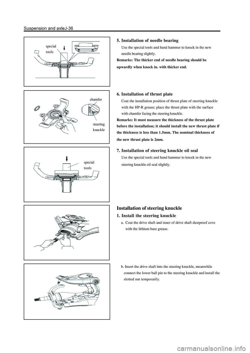
5. Installation of needle bearing
Use the special tools and hand hammer to knock in the new
needle bearing slightly.
Remarks: The thicker end of needle bearing should be
upwardly when knock in. with thicker end.
chamfer
steering
knuckle
6. Installation of thrust plate
Coat the installation position of thrust plate of steering knuckle
with the HP-R grease; place the thrust plate with the surface
with chamfer facing the steering knuckle.
Remarks: It must measure the thickness of the thrust plate
before the installation; it should install the new thrust plate if
the thickness is less than 1.5mm. The nominal thickness of
the new thrust plate is 2mm.
7. Installation of steering knuckle oil seal
Use the special tools and hand hammer to knock in the new
steering knuckle oil seal slightly.
Installation of steering knuckle
1. Install the steering knuckle
a. Coat the drive shaft and inner of drive shaft dustproof cove
with the lithium base grease.
b. Insert the drive shaft into the steering knuckle, meanwhile
connect the lower ball pin to the steering knuckle and install the
slotted nut temporarily.
special
tools
special
tools
Page 233 of 425
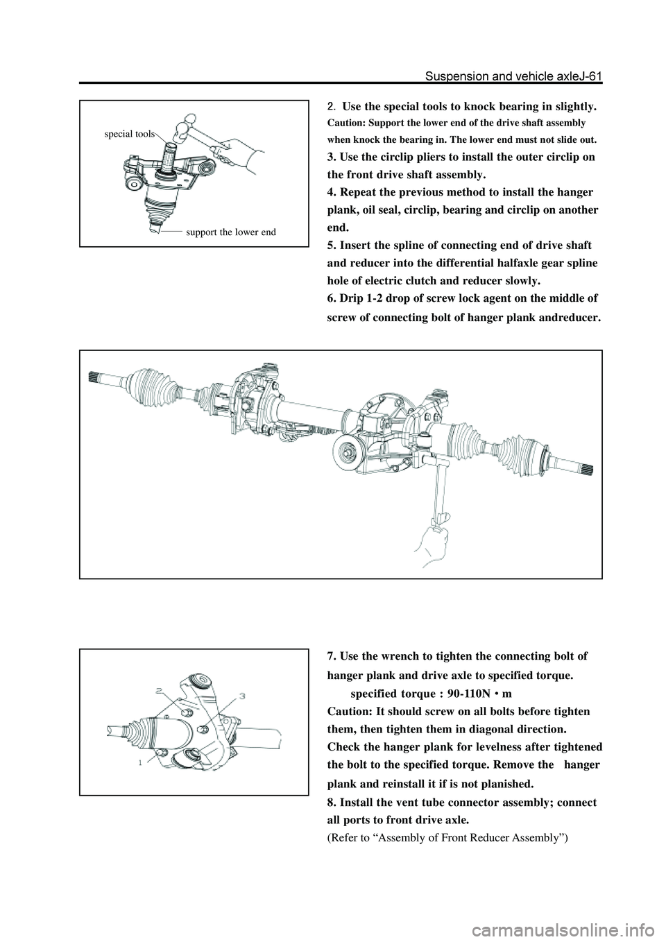
Use the special tools to knock bearing in slightly.
Caution: Support the lower end of the drive shaft assembly
when knock the bearing in. The lower end must not slide out.
3. Use the circlip pliers to install the outer circlip on
the front drive shaft assembly.
4. Repeat the previous method to install the hanger
plank, oil seal, circlip, bearing and circlip on another
end.
5. Insert the spline of connecting end of drive shaft
and reducer into the differential halfaxle gear spline
hole of electric clutch and reducer slowly.
6. Drip 1-2 drop of screw lock agent on the middle of
screw of connecting bolt of hanger plank andreducer.
7. Use the wrench to tighten the connecting bolt of
hanger plank and drive axle to specified torque.
specified torque : 90-110N
m
Caution: It should screw on all bolts before tighten
them, then tighten them in diagonal direction.
Check the hanger plank for levelness after tightened
the bolt to the specified torque. Remove the hanger
plank and reinstall it if is not planished.
8. Install the vent tube connector assembly; connect
all ports to front drive axle.
(Refer to “Assembly of Front Reducer Assembly”)
special tools
support the lower end
Page 245 of 425
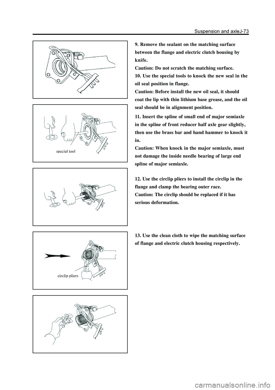
9. Remove the sealant on the matching surface
between the flange and electric clutch housing by
knife.
Caution: Do not scratch the matching surface.
10. Use the special tools to knock the new seal in the
oil seal position in flange.
Caution: Before install the new oil seal, it should
coat the lip with thin lithium base grease, and the oil
seal should be in alignment position.
11. Insert the spline of small end of major semiaxle
in the spline of front reducer half axle gear slightly,
then use the brass bar and hand hammer to knock it
in.
Caution: When knock in the major semiaxle, must
not damage the inside needle bearing of large end
spline of major semiaxle.
12. Use the circlip pliers to install the circlip in the
flange and clamp the bearing outer race.
Caution: The circlip should be replaced if it has
serious deformation.
13. Use the clean cloth to wipe the matching surface
of flange and electric clutch housing respectively.
Page 265 of 425
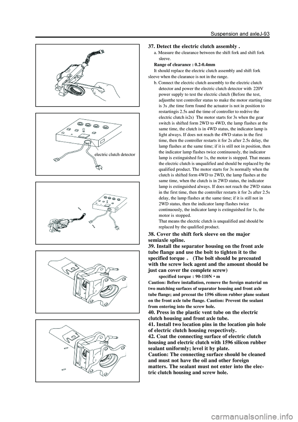
electric clutch detector
37. Detect the electric clutch assembly .
a. Measure the clearance between the shift fork and shift fork
sleeve.
Range of clearance : 0.2-0.4mm
It should replace the electric clutch assembly and shift fork
sleeve when the clearance is not in the range.
b. Connect the electric clutch assembly to the electric clutch
detector and power the electric clutch detector with220V
power supply to test the electric clutch (Before the test,
adjustthe test controller status to make the motor starting time
is 3s ,the time form found the actuator is not in position to
restartingis 2.5s and the time of controller to redrive the
electric clutch is2s) The motor starts for 3s when the gear
switch is shifted form 2WD to 4WD, the lamp flashes at the
same time, the clutch is in 4WD status, the indicator lamp is
light always. If does not reach the 4WD status in the first
time, then the controller restarts it for 2s after 2.5s delay, the
lamp flashes at the same time; if it is still not in position, then
the indicator lamp flashes twice continuously, the indicator
lamp is extinguished for 1s, the motor is stopped. That means
the electric clutch is unqualified and should be replaced by the
qualified product. The motor starts for 3s normally when the
clutch is shifted form 4WD to 2WD, the lamp flashes at the
same time, when the clutch is in 2WD status, the indicator
lamp is extinguished always. If does not reach the 2WD status
in the first time, then the controller restarts it for 2s after 2.5s
delay, the lamp flashes at the same time; if it is still not in
2WD status, then the indicator lamp flashes twice
continuously, the indicator lamp is extinguished for 1s, the
motor is stopped.
That means the electric clutch is unqualified and should be
replaced by the qualified product.
38. Cover the shift fork sleeve on the major
semiaxle spline.
39. Install the separator housing on the front axle
tube flange and use the bolt to tighten it to the
specified torque
(The bolt should be precoated
with the screw lock agent and the amount should be
just can cover the complete screw)
specified torque : 90-110Nm
Caution: Before installation, remove the foreign material on
two matching surfaces of separator housing and front axle
tube flange; and precoat the 1596 silicon rubber plane sealant
on the front axle tube flange. Caution: Prevent the sealant
from entering into the screw hole.
40. Press in the plastic vent tube on the electric
clutch housing and front axle tube.
41. Install two location pins in the location pin hole
of electric clutch housing respectively.
42. Coat the connecting surface of electric clutch
housing and electric clutch with 1596 silicon rubber
sealant uniformly; level it by plate.
Caution: The connecting surface should be cleaned
and must not have the oil and other foreign
matters. The sealant must not enter into the elec-
tric clutch housing and screw hole.
Page 291 of 425
Brake-5
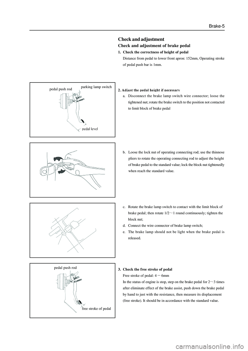
Check and adjustment
Check and adjustment of brake pedal
1. Check the correctness of height of pedal
Distance from pedal to lower front apron: 152mm, Operating stroke
of pedal push bar is 1mm.
a. Disconnect the brake lamp switch wire connector; loose the
tightened nut; rotate the brake switch to the position not contacted
to limit block of brake pedal
b. Loose the lock nut of operating connecting rod; use the thinnose
pliers to rotate the operating connecting rod to adjust the height
of brake pedal to the standard value; lock the block nut tightenedly
when reach the standard value.
c. Rotate the brake lamp switch to contact with the limit block of
brake pedal; then rotate 1/2
1 round continuously; tighten the
block nut;
d. Connect the wire connector of brake lamp switch;
e. The brake lamp should not be light when the brake pedal is
released.
3. Check the free stroke of pedal
Free stroke of pedal: 4
6mm
In the status of engine is stop, step on the brake pedal for 2
3 times
after eliminate effect of the brake assist, push down the brake pedal
by hand to just with the resistance, then measure its displacement
(free stroke). It should be in accordance with the standard value.
pedal push rodparking lamp switch
free stroke of pedal pedal push rod