sensor GREAT WALL HOVER 2006 Service Owner's Manual
[x] Cancel search | Manufacturer: GREAT WALL, Model Year: 2006, Model line: HOVER, Model: GREAT WALL HOVER 2006Pages: 425, PDF Size: 26.05 MB
Page 357 of 425
CD Player and Air Conditioning System-4
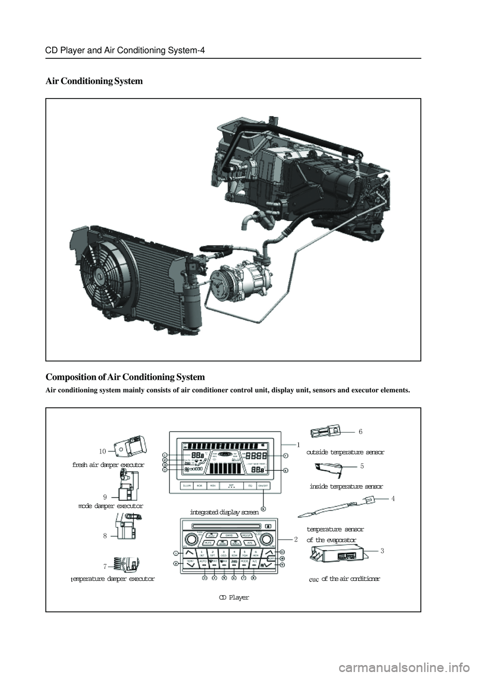
Air Conditioning System
Composition of Air Conditioning System
Air conditioning system mainly consists of air conditioner control unit, display unit, sensors and executor elements.
fresh air damper executor
mode damper executor
emperature damper executor
integrated display screen
CD Player
outside temperature sensor
inside temperature sensor
temperature sensor
of the evaporator
of the air conditioner
Page 358 of 425
CD Player and Air Conditioning System-5
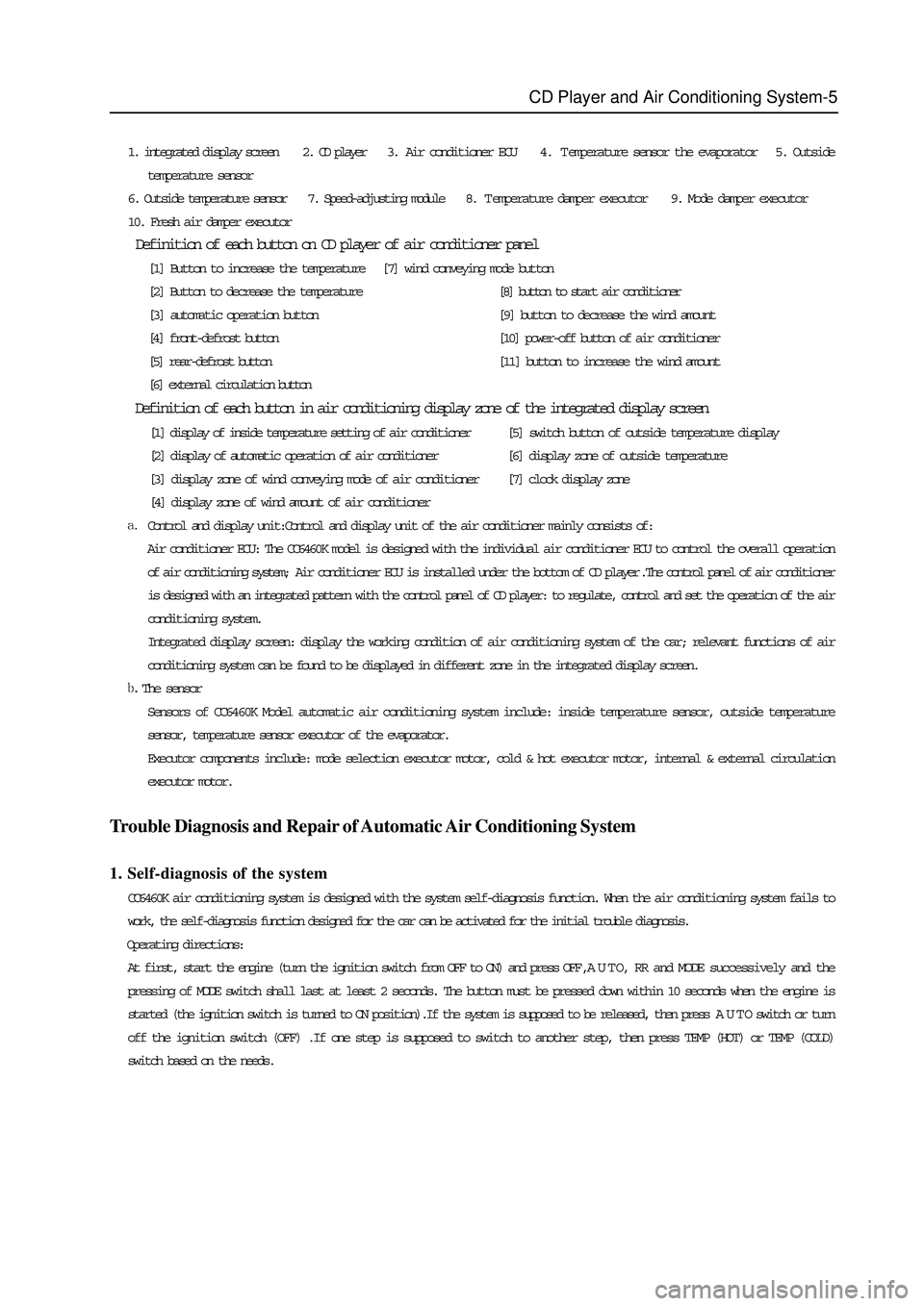
1. integrated display screen 2. CD player 3. Air conditioner ECU 4. Temperature sensor the evaporator 5. Outside
temperature sensor
6. Outside temperature sensor 7. Speed-adjusting module 8. Temperature damper executor 9. Mode damper executor
10. Fresh air damper executor
Definition of each button on CD player of air conditioner panel
[1] Button to increase the temperature [7] wind conveying mode button
[2] Button to decrease the temperature[8] button to start air conditioner
[3] automatic operation button[9] button to decrease the wind amount
[4] front-defrost button[10] power-off button of air conditioner
[5] rear-defrost button[11] button to increase the wind amount
[6] external circulation button
Definition of each button in air conditioning display zone of the integrated display screen
[1] display of inside temperature setting of air conditioner[5] switch button of outside temperature display
[2] display of automatic operation of air conditioner[6] display zone of outside temperature
[3] display zone of wind conveying mode of air conditioner[7] clock display zone
[4] display zone of wind amount of air conditioner
Control and display unit:Control and display unit of the air conditioner mainly consists of:
Air conditioner ECU: The CC6460K model is designed with the individual air conditioner ECU to control the overall operation
of air conditioning system; Air conditioner ECU is installed under the bottom of CD player.The control panel of air conditioner
is designed with an integrated pattern with the control panel of CD player: to regulate, control and set the operation of the air
conditioning system.
Integrated display screen: display the working condition of air conditioning system of the car; relevant functions of air
conditioning system can be found to be displayed in different zone in the integrated display screen.
The sensor
Sensors of CC6460K Model automatic air conditioning system include: inside temperature sensor, outside temperature
sensor, temperature sensor executor of the evaporator.
Executor components include: mode selection executor motor, cold & hot executor motor, internal & external circulation
executor motor.
Trouble Diagnosis and Repair of Automatic Air Conditioning System
1. Self-diagnosis of the system
CC6460K air conditioning system is designed with the system self-diagnosis function. When the air conditioning system fails to
work, the self-diagnosis function designed for the car can be activated for the initial trouble diagnosis.
Operating directions:
At first, start the engine (turn the ignition switch from OFF to ON) and press OFF , A U T O, RR and MODE successively and the
pressing of MODE switch shall last at least 2 seconds. The button must be pressed down within 10 seconds when the engine is
started (the ignition switch is turned to ON position).If the system is supposed to be released, then press A U T O switch or turn
off the ignition switch (OFF) .If one step is supposed to switch to another step, then press TEMP (HOT) or TEMP (COLD)
switch based on the needs.
Page 359 of 425
CD Player and Air Conditioning System-6
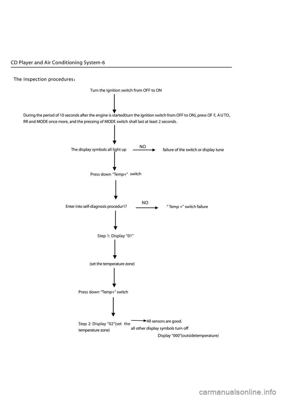
Turn the ignition switch from OFF to ON
The display symbols all light up
failure of the switch or display tune
NO
Press down “Temp+” switch
Enter into self-diagnosis procedur1?
NO“ Te mp +” switch failure
Step 1:
Display “01”
(set t he temperature zone)
all other display symbols turn of
f
Press
down
“Temp+” switch
Step 2: Display
“02”(set the
temperature
z one)
The inspection procedures
During the period of 10 seconds after the engine is started(turn the ignition switch from OFF to ON), press OF F, A U T O ,
RR and MODE once more, and the pressing of MODE switch shall last at least 2 seconds
.
A ll sensors are good.
Display
“000”(outsidetemperature)
Page 360 of 425
CD Player and Air Conditioning System-7
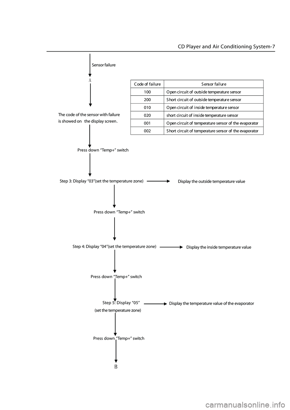
C ode off ailu re S ensor f ai lure
10 0 O pen c ircu itof outsid e t em perature sens or
20 0 S hortcirc uit o f o utside temp eratur e s ensor
01 0 O pen c ircu itof i nside temp eratur e s ensor
02 0 s hortcirc ui t o f ins ide t em perature sens or
00 1 O pen c ircu itof temp erat ur e s ensor o f the evap orator
00 2 S hortcirc uit o f tem perature sens or ofthe e vapo rator
Step 3: Display “03”(set the temperature zone)
Display the outside temperature value
Press down “Temp+” switch
Step 4: Display “04”(set the temperature zone
)
Sensor
failure
The code of the sensor with failure
is showed on the display screen
.
Press down
“Temp+” switch
Press down
“Temp+” switch
Step 5:
Display “05”
(set t he temperature zone)
Display the inside temperature value
Display the temperature value of the evaporator
Press down
“Temp+” switch
Page 374 of 425
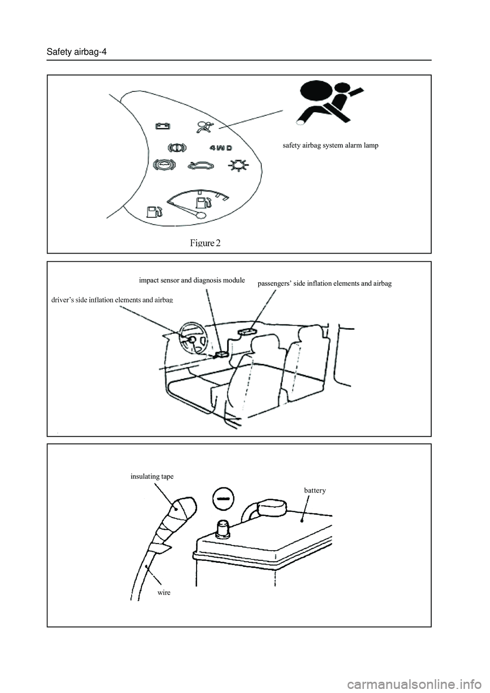
Safety airbag-4
safety airbag system alarm lamp
impact sensor and diagnosis module
passengers’ side inflation elements and airbag
insulating tape
battery
wire
Page 377 of 425
Safety airbag-7
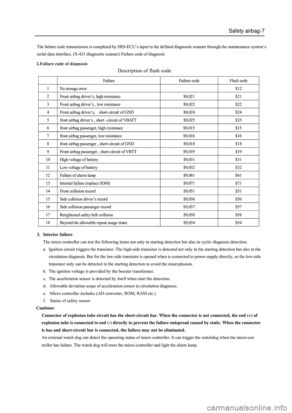
Description of flash code
The failure code transmission is completed by SRS-ECU’s input to the defined diagnostic scanner through the maintenance system’s
serial data interface. (X-431 diagnostic scanner) Failure code of diagnosis
Failure Failure code Flash code
1 No storage error $12
2 Front airbag driver’s, high resistance $9,021 $21
3 Front airbag driver’s , low resistance $9,022 $22
4 Front airbag driver ’s, short-circuit of GND $9,024 $24
5 front airbag driver ’s , short –circuit of VBATT $9,025 $25
6 front airbag passenger, high resistance $9,015 $15
7 front airbag passenger, low resistance $9,016 $16
8 front airbag passenger , short-circuit of GND $9,018 $18
9 Front airbag passenger , short-circuit of VBTT $9,019 $19
10 High voltage of battery $9,031 $31
11 Low voltage of battery $9,032 $32
12 Failure of alarm lamp $9,061 $61
13 Internal failure (replace SDM) $9,071 $71
14 Front collision record $9,051 $51
15 Side collision driver’s record $9,056 $56
16 Side collision passenger record $9,057 $57
17 Retightened safety belt collision $9,058 $58
18 Beyond the allowable repeat usage times $9,054 $54
3. Interior failure
The micro controller can test the following items not only in starting detection but also in cyclic diagnosis detection.
a. Ignition circuit triggers the transistor: The high-side transistor is detected not only in the starting detection but also in the
circulation diagnosis. But for the low-side transistor is opened when is connected to power supply directly, so the low-side
transistor only can be detected in the starting detection to avoid the misexplosion.
b. The ignition voltage is provided by the booster transformer.
c. The acceleration sensor is detected by itself when start the detection.
d. Allowable deviation scope of acceleration sensor in circulation diagnosis.
e. Micro controller includes (AD converter, ROM, RAM etc.)
f. Status of safety sensor
Cautions:
Connector of explosion tube circuit has the short-circuit bar. When the connector is not connected, the end (+) of
explosion tube is connected to end (-) directly to prevent the failure outspread caused by static. When the connector
is bas and short-circuit bar is connected, the failure may not be eliminated.
An external watch dog can detect the operating status of micro controller. It can trigger the watchdog when the micro con
troller has failure. The watch dog will reset the micro-controller and light the alarm lamp.
Page 378 of 425
Safety airbag-8
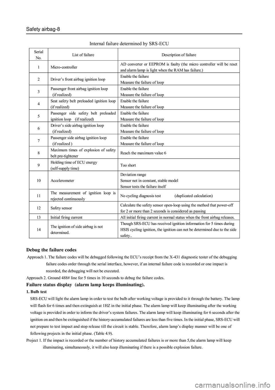
Internal failure determined by SRS-ECU
Serial
No. List of failure Description of failure
1 Micro-controller AD converter or EEPROM is faulty (the micro controller will be reset
and alarm lamp is light when the RAM has failure.)
2 Driver’s front airbag ignition loop Enable the failure
Measure the failure of loop
3 Passenger front airbag ignition loop
(if realized) Enable the failure
Measure the failure of loop
4 Seat safety belt preloaded ignition loop
(if realized) Enable the failure
Measure the failure of loop
5 Passenger side safety belt preloaded
ignition loop (if realized) Enable the failure
Measure the failure of loop
6 Driver’s side airbag ignition loop
(if realized) Enable the failure
Measure the failure of loop
7 Passenger side airbag ignition loop
(if realized ) Enable the failure
Measure the failure of loop
8 Maximum times of explosion of safet y
belt pre-tightener Reach the maximum value 6
9 Holding time of ECU ener gy
(self-supply time) Too short
10 Accelerometer Deviation range
Sensor not in constant, stable model
Sensor tests the failure itself
11 The measurement of ignition loop is
rejected continuously No cycling diagnosis test (duplicated calculation)
12 Safety sensor Calculate the safety sensor open-loop using the method that power-off
for 2 or more than 2 seconds is considered as passing
13 Initial firing current All initial firing current in normal status when the front airbag releases.
14 The ignition of side airbag is not
determined. Though SRS-ECU has received ignition information for 5 times during
HSIS cycling ignition, the ignition can not be determined due to the side
safety..
Debug the failure codes
Approach 1. The failure codes will be debugged following the ECU’s receipt from the X-431 diagnostic tester of the debugging
failure codes order through the serial interface, however, if an internal failure code is recorded or one impact is
recorded, the debugging will not be executed.
Approach 2. Ground 488# line for 5 times in 10 seconds to debug the failure codes.
Failure status display (alarm lamp keeps illuminating).
1. Bulb test
SRS-ECU will light the alarm lamp in order to test the bulb after working voltage is provided to it through the battery. The lamp
will flash for 6 times and then extinguish at 1HZ in the initial phase. The alarm lamp will keep illuminating after the working
voltage is provided in order to inform the driver’s system failures. The alarm lamp will keep illuminating for 6 seconds after the
ignition on and then be extinguished if the history-accumulated failures are less than five times. In the initial phase, SRS-ECU will
not prepare to test impact and stop release till the circuit is stable. Therefore, alarm lamp’s display manner will be one of
following projects in the initial phase. (Table 4.9).
Project 1. If the impact is recorded or the number of history accumulated failures is or more than 5,the alarm lamp will keep
illuminating, simultaneously, it will also keep illuminating if there is a possible explosion failure.