battery GREAT WALL HOVER 2006 Service Repair Manual
[x] Cancel search | Manufacturer: GREAT WALL, Model Year: 2006, Model line: HOVER, Model: GREAT WALL HOVER 2006Pages: 425, PDF Size: 26.05 MB
Page 121 of 425

Automatic transmission-45
Diagnosis and test
Test system
1. Recommended test equipment and program
The test equipment and control unit for design will be used for the test of all vehicles. The parts for transmission test includes:
Tester for service after sales
Special vehicle for test
2. Tester for service after sales
After the special programming, the tester equipped with special car test software can be used to test the specified system and unit.
The program allows the normal communication between the transmission control units (TCUs) .
The computer needs the required information from the customer and select the necessary data through the manual. For example:
view the code, clear the error code and make the real-time operation. For detailed operating instruction refer to user’s manual.
The equipment can be used by the trained specialized persons, such as technician, machinist to test the electronic and loop
problem related to transmission. The testable information includes: the engine speed, rode (shaft speed), transmission fluid
temperature, position of throttle position, status of solenoid valve and gear and position of operating lever. Additionally, it can be
used to detect the current and stored problem.
3. Description of TCU pin
The description of TCU pin code had been listed in Table 6.1.1
For description of wire bunch refer to Figure 6.1.1
Pin No. Function Type 2WD description
A14 Public grounding GND
● Negative pole of TCU supply, connected to negative pole of
battery.
A13 Nonuse
--
○ -----
A12 M ode indicator la mp
Snowland mode OP
● Indicate that select the “Snowland M ode” operating method.
A11 Parking-Gear indicator lamp O P
● T he drive instrum ent panel indicator la mp indicates tha t is in
the “Parking G ear”
A10 Reverse-Gear indicator lamp OP
● T he drive instrum ent panel indicator la mp indicates tha t is in
“ Revers e G ear”
A9 N-G ear indicator lamp O P
● T he drive instrum ent panel indicator la mp indicates tha t is in
“Idle N Gear”
A8 Nonuse -- ○ -----
A7 Nonuse -- ○ -----
A6 M ode indicator la mp
dynamic mode OP
● Indicate that select the “ dyna m ic mode” operating method.
A5 Nonuse ―― ○ ---――
A4 Nonuse ―― ○ -----
A3 Nonuse ―― ○ -----
A2 Mode switch IP
● The switch is used to select the “economic mode”, “dynamic
m ode” and “ snowla nd mode”. T he voltage is varia ble in
range of 0 V-2V .
A1 Nonuse ―― ○ -----
A30 Power supply PWR
● Power supply for TCU; is the main power source of drive
unit and solenoid valve.
A29 Nonuse ―― ○ -----
A28 1st-G ear indicator lamp
/1st-G ear position﹡ OP
● Drive the instrument panel indicator lamp indication, indicate
that the gear-position is in “1st-G ear”
A27 2nd-G ear indicator lamp
/2nd-G ear position OP
● Drive the instrument panel indicator lamp indication, indicate
that the gear-position is in “2nd-G ear”
A26 3rd-G ear indicator lamp
/3rd-Gear position﹡ OP
● Drive the instrument panel indicator lamp indication, indicate
that the gear-position is in “3rd-Gear”
A25 Automatic gear indicator
lamp /4th –Gear position OP
● Drive the instrument panel indicator lamp indication, indicate
that the gear-position is in “automatic-Gear”
Page 124 of 425
Automatic transmission-48
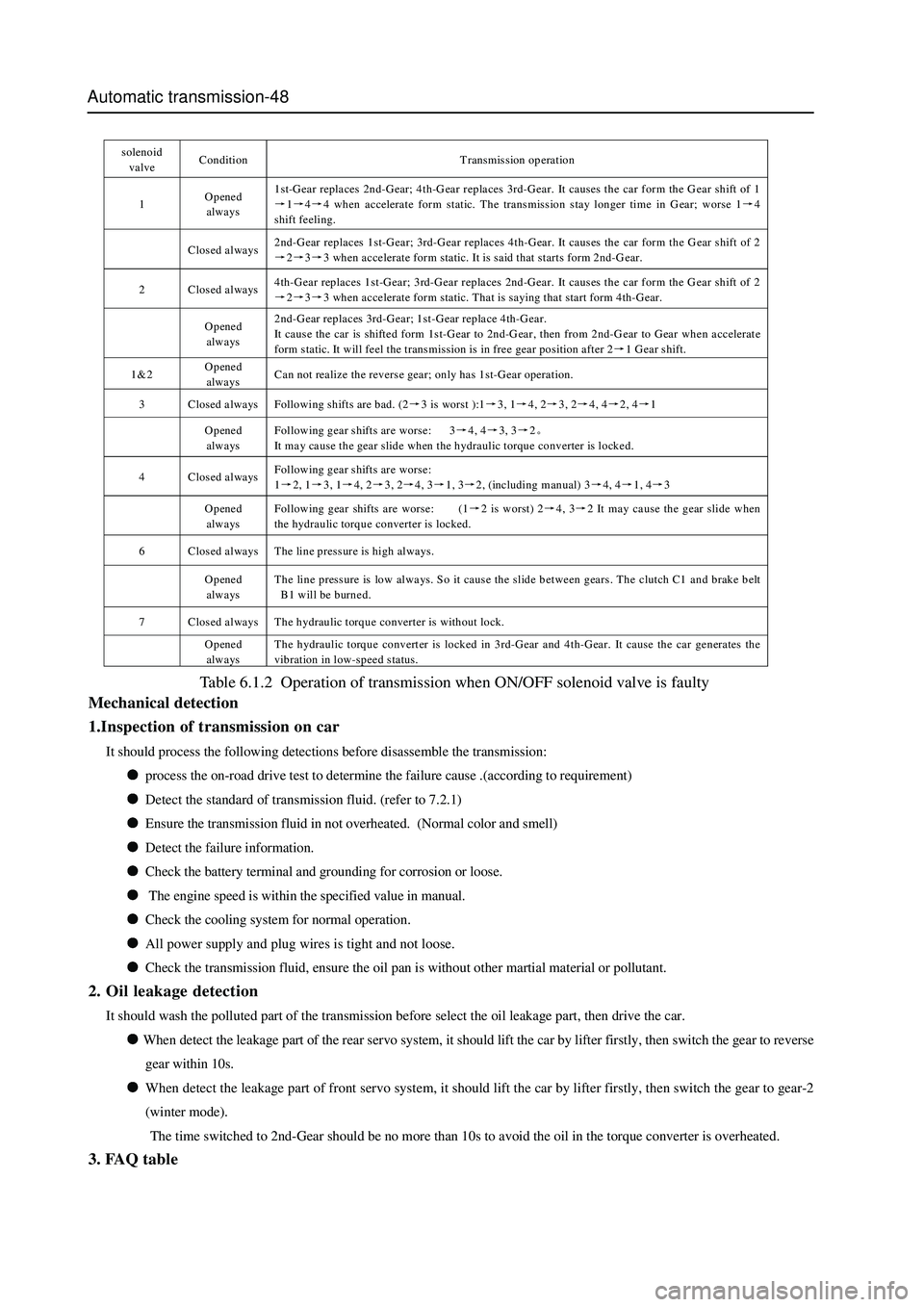
s oleno id
valve Condition Transmission operation
1 Opened
always 1st-Gear replaces 2nd-Gear; 4th-Gear replaces 3rd-Gear. It causes the car form the G ear shift of 1
→1→4→4 when accelerate form static. The transmission stay longer time in Gear; worse 1→4
shift feeling.
Closed always 2nd-Gear replaces 1st-Gear; 3rd-Gear replaces 4th-Gear. It causes the car form the G ear shift of 2
→2→3→3 when accelerate form static. It is said that starts form 2nd-Gear.
2 Closed always 4th-Gear replaces 1st-Gear; 3rd-Gear replaces 2nd-Gear. It causes the car form the G ear shift of 2
→2→3→3 when accelerate form static. That is saying that start form 4th-Gear.
Opened
always 2nd-Gear replaces 3rd-Gear; 1st-Gear replace 4th-Gear.
It cause the car is shifted form 1st-Gear to 2nd-Gear, then from 2nd-G ear to Gear when accelerate
form static. It will feel the transmission is in free gear position after 2→1 Gear shift.
1&2 Opened
always Can not realize the reverse gear; only has 1st-Gear operation.
3 Closed always Following shifts are bad. (2→3 is worst ):1→3, 1→4, 2→3, 2→4, 4→2, 4→1
Opened
always Following gear shifts are worse: 3→4, 4→3, 3→2。
It may cause the gear slide when the hydraulic torque converter is locked.
4 Closed always Following gear shifts are worse:
1→2, 1→3, 1→4, 2→3, 2→4, 3→1, 3→2, (including manual) 3→4, 4→1, 4→3
Opened
always Following gear shifts are worse: (1→2 is worst) 2→4, 3→2 It may cause the gear slide when
the hydraulic torque converter is locked.
6 Closed always The line pressure is high always.
Opened
always The line pressure is low always. So it cause the slide between gears. The clutch C1 and brake belt
B1 will be burned.
7 Closed always The hydraulic torque converter is without lock.
Opened
always The hydraulic torque converter is locked in 3rd-Gear and 4th-Gear. It cause the car generates the
vibration in low-speed status.
Table 6.1.2 Operation of transmission when ON/OFF solenoid valve is faulty
Mechanical detection
1.Inspection of transmission on car
It should process the following detections before disassemble the transmission:
process the on-road drive test to determine the failure cause .(according to requirement)
Detect the standard of transmission fluid. (refer to 7.2.1)
Ensure the transmission fluid in not overheated. (Normal color and smell)
Detect the failure information.
Check the battery terminal and grounding for corrosion or loose.
The engine speed is within the specified value in manual.
Check the cooling system for normal operation.
All power supply and plug wires is tight and not loose.
Check the transmission fluid, ensure the oil pan is without other martial material or pollutant.
2. Oil leakage detection
It should wash the polluted part of the transmission before select the oil leakage part, then drive the car.
When detect the leakage part of the rear servo system, it should lift the car by lifter firstly, then switch the gear to reverse
gear within 10s.
When detect the leakage part of front servo system, it should lift the car by lifter firstly, then switch the gear to gear-2
(winter mode).
The time switched to 2nd-Gear should be no more than 10s to avoid the oil in the torque converter is overheated.
3. FAQ table
Page 131 of 425
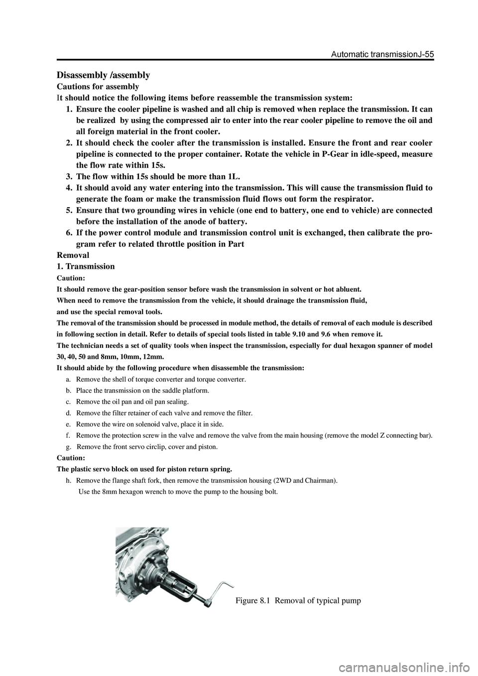
Figure 8.1 Removal of typical pump
Disassembly /assembly
Cautions for assembly
It should notice the following items before reassemble the transmission system:
1. Ensure the cooler pipeline is washed and all chip is removed when replace the transmission. It can
be realized by using the compressed air to enter into the rear cooler pipeline to remove the oil and
all foreign material in the front cooler.
2. It should check the cooler after the transmission is installed. Ensure the front and rear cooler
pipeline is connected to the proper container. Rotate the vehicle in P-Gear in idle-speed, measure
the flow rate within 15s.
3. The flow within 15s should be more than 1L.
4. It should avoid any water entering into the transmission. This will cause the transmission fluid to
generate the foam or make the transmission fluid flows out form the respirator.
5. Ensure that two grounding wires in vehicle (one end to battery, one end to vehicle) are connected
before the installation of the anode of battery.
6. If the power control module and transmission control unit is exchanged, then calibrate the pro-
gram refer to related throttle position in Part
Removal
1. Transmission
Caution:
It should remove the gear-position sensor before wash the transmission in solvent or hot abluent.
When need to remove the transmission from the vehicle, it should drainage the transmission fluid,
and use the special removal tools.
The removal of the transmission should be processed in module method, the details of removal of each module is described
in following section in detail. Refer to details of special tools listed in table 9.10 and 9.6 when remove it.
The technician needs a set of quality tools when inspect the transmission, especially for dual hexagon spanner of model
30, 40, 50 and 8mm, 10mm, 12mm.
It should abide by the following procedure when disassemble the transmission:
a. Remove the shell of torque converter and torque converter.
b. Place the transmission on the saddle platform.
c. Remove the oil pan and oil pan sealing.
d. Remove the filter retainer of each valve and remove the filter.
e. Remove the wire on solenoid valve, place it in side.
f. Remove the protection screw in the valve and remove the valve from the main housing (remove the model Z connecting bar).
g. Remove the front servo circlip, cover and piston.
Caution:
The plastic servo block on used for piston return spring.
h. Remove the flange shaft fork, then remove the transmission housing (2WD and Chairman).
Use the 8mm hexagon wrench to move the pump to the housing bolt.
Page 351 of 425
Controller of the Central Door Lock
1. Positive pole of the power supply (12V) is connected to the positive pole of car’s battery through a 15A fuse; when the
engine is started, the voltage is not less than 10V.
2. Output of the central door lock. The unlock cable connected to the executor of the central door lock is usuall
y grounded
through the normally-closed contact of the internal relay; when the door is unlocked by the remote controller or unlocked
manually, the public contact of the relay will get through with the normally-open contact, realizing an output of 12V
voltage.
3. Out
put of the central door lock. The lock cable connected to the executor of the central door lock is usually grounded
through the normally-closed contact of the internal relay; when the door is locked by the remote controller or locked
manually, the public contact of the relay will get through the normally-open contact, realizing an output of 12V voltage.
4. Key detection cable. This cable is connected to the ignition lock of the car and will
get through with the grounding wire
when the key is inserted into. (negative input)
5. Ri
ght direction indicator. The cable is connected to the positive pole of the right direction indicator of the car; an output of
12V voltage will be available when this cable is at work.
6. Left direction indicator. The cable is connected to the
positive pole of the right direction indicator of the car; an output of
12V voltage will be available when this cable is at work.
7. Negative input of door switch, which is connected to the door switch of the car; this cable will be earthed when the door is
opened. (Interior lights will be on)
a. Open the door and then close it, the reading light will be on for 10 seconds; if during this period, it is detected that the key has
been inserted into the ignition lock or the door closed, then the reading light will turn off.
b. When the key is pulled out of the ignition lock, then reading light will turn on, during this period, if the key is reinserted into
the ignition lock or the door lock, the reading light will be off; if there is not any action when the door is closed within 1
minute, the reading light will automatically turn off.
8. ON power supply detection cable. A conductive wire connected to the ON gear of the ignition lock. (When the ke
y is turned
to the ON position, a 12V output will be available)
9. Car s
peedometer detection cable, which is connected to the detection cable of car's speedometer. (When the car is
accelerated to the speed of 15km/h, the instruments unit will out
put a 500mS rectangular positive pulse to the central door
lock controller, which will control the locking of the central door lock when this 500mS rectangular positive pulse signal is
detected by the controller.)
10. Output of window closing si
gnal. When the door is locked by the remote controller, this line will be available with an
output of 12V positive current for one second and then be off. (No output)
11. Locking signal. The locking signal line connected to the central door lock of car's left front door is connected throu
gh with
the grounding line when at work. (Earthing)
12. Unlockin
g signal. The unlocking signal line connected to the central door lock of car's left front door is connected through
with the grounding line when at work. (Earthing)
13. Ne
gative pole of the power supply, which is connected to the car body, (earthing) line shall be as short as possible,
over-length will produce the interference.
Function of controller of the central door lock
1. Locking. When all the car doors are closed, press LOCK button of the remote controller once, at this time, the direction
indicator will flash once and the central door lock is closed.
2. Unlocking. At the locking state, press UNLOCK button of the remote controller once, at this time, the direction indicato
r
will flash two times and the central door lock is opened.
3. Car-findin
g function. At the locking state, press LOCK bottom of the remote controller once, and at this time, the direction
indicator will flash ten times quickly. Press UNLOCK button of the remote controller to quit the car-finding function.
4. Automatic
prevention function. At the locking state, press UNLOCK button of the remote controller to open the lock; if the
Page 374 of 425
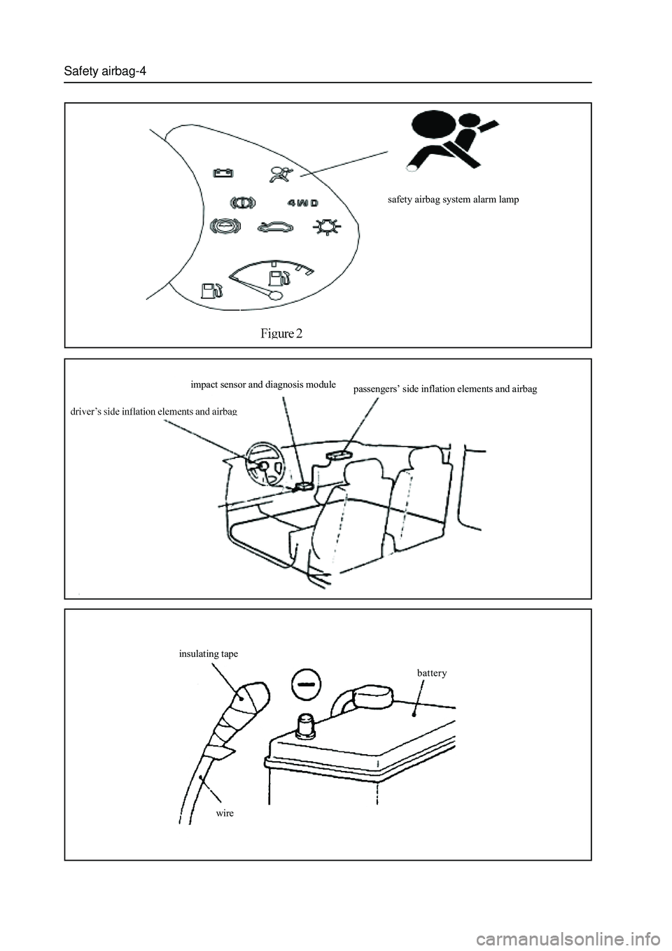
Safety airbag-4
safety airbag system alarm lamp
impact sensor and diagnosis module
passengers’ side inflation elements and airbag
insulating tape
battery
wire
Page 377 of 425
Safety airbag-7
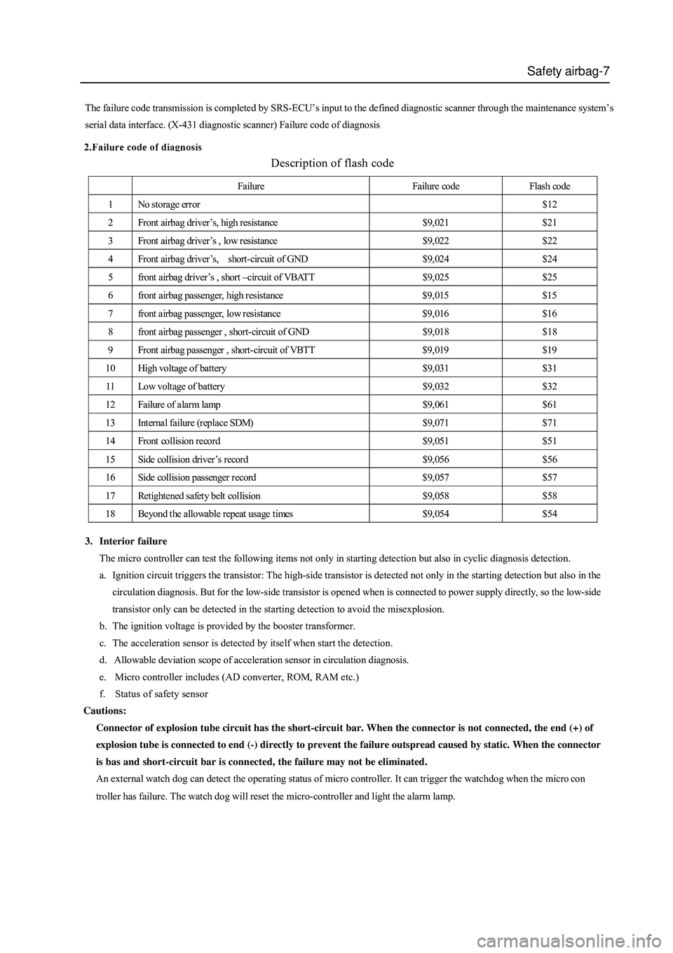
Description of flash code
The failure code transmission is completed by SRS-ECU’s input to the defined diagnostic scanner through the maintenance system’s
serial data interface. (X-431 diagnostic scanner) Failure code of diagnosis
Failure Failure code Flash code
1 No storage error $12
2 Front airbag driver’s, high resistance $9,021 $21
3 Front airbag driver’s , low resistance $9,022 $22
4 Front airbag driver ’s, short-circuit of GND $9,024 $24
5 front airbag driver ’s , short –circuit of VBATT $9,025 $25
6 front airbag passenger, high resistance $9,015 $15
7 front airbag passenger, low resistance $9,016 $16
8 front airbag passenger , short-circuit of GND $9,018 $18
9 Front airbag passenger , short-circuit of VBTT $9,019 $19
10 High voltage of battery $9,031 $31
11 Low voltage of battery $9,032 $32
12 Failure of alarm lamp $9,061 $61
13 Internal failure (replace SDM) $9,071 $71
14 Front collision record $9,051 $51
15 Side collision driver’s record $9,056 $56
16 Side collision passenger record $9,057 $57
17 Retightened safety belt collision $9,058 $58
18 Beyond the allowable repeat usage times $9,054 $54
3. Interior failure
The micro controller can test the following items not only in starting detection but also in cyclic diagnosis detection.
a. Ignition circuit triggers the transistor: The high-side transistor is detected not only in the starting detection but also in the
circulation diagnosis. But for the low-side transistor is opened when is connected to power supply directly, so the low-side
transistor only can be detected in the starting detection to avoid the misexplosion.
b. The ignition voltage is provided by the booster transformer.
c. The acceleration sensor is detected by itself when start the detection.
d. Allowable deviation scope of acceleration sensor in circulation diagnosis.
e. Micro controller includes (AD converter, ROM, RAM etc.)
f. Status of safety sensor
Cautions:
Connector of explosion tube circuit has the short-circuit bar. When the connector is not connected, the end (+) of
explosion tube is connected to end (-) directly to prevent the failure outspread caused by static. When the connector
is bas and short-circuit bar is connected, the failure may not be eliminated.
An external watch dog can detect the operating status of micro controller. It can trigger the watchdog when the micro con
troller has failure. The watch dog will reset the micro-controller and light the alarm lamp.
Page 378 of 425
Safety airbag-8
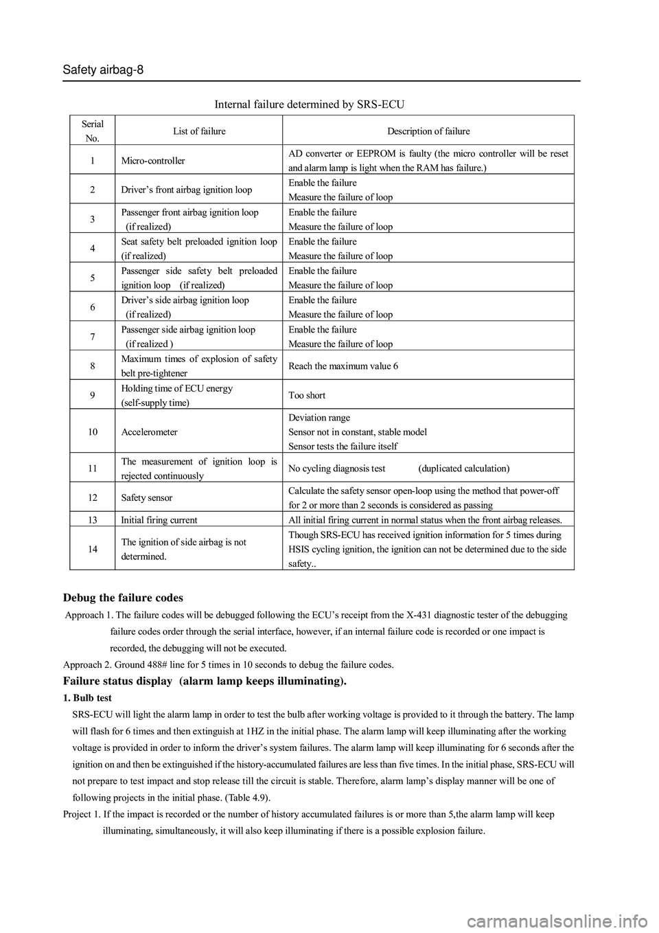
Internal failure determined by SRS-ECU
Serial
No. List of failure Description of failure
1 Micro-controller AD converter or EEPROM is faulty (the micro controller will be reset
and alarm lamp is light when the RAM has failure.)
2 Driver’s front airbag ignition loop Enable the failure
Measure the failure of loop
3 Passenger front airbag ignition loop
(if realized) Enable the failure
Measure the failure of loop
4 Seat safety belt preloaded ignition loop
(if realized) Enable the failure
Measure the failure of loop
5 Passenger side safety belt preloaded
ignition loop (if realized) Enable the failure
Measure the failure of loop
6 Driver’s side airbag ignition loop
(if realized) Enable the failure
Measure the failure of loop
7 Passenger side airbag ignition loop
(if realized ) Enable the failure
Measure the failure of loop
8 Maximum times of explosion of safet y
belt pre-tightener Reach the maximum value 6
9 Holding time of ECU ener gy
(self-supply time) Too short
10 Accelerometer Deviation range
Sensor not in constant, stable model
Sensor tests the failure itself
11 The measurement of ignition loop is
rejected continuously No cycling diagnosis test (duplicated calculation)
12 Safety sensor Calculate the safety sensor open-loop using the method that power-off
for 2 or more than 2 seconds is considered as passing
13 Initial firing current All initial firing current in normal status when the front airbag releases.
14 The ignition of side airbag is not
determined. Though SRS-ECU has received ignition information for 5 times during
HSIS cycling ignition, the ignition can not be determined due to the side
safety..
Debug the failure codes
Approach 1. The failure codes will be debugged following the ECU’s receipt from the X-431 diagnostic tester of the debugging
failure codes order through the serial interface, however, if an internal failure code is recorded or one impact is
recorded, the debugging will not be executed.
Approach 2. Ground 488# line for 5 times in 10 seconds to debug the failure codes.
Failure status display (alarm lamp keeps illuminating).
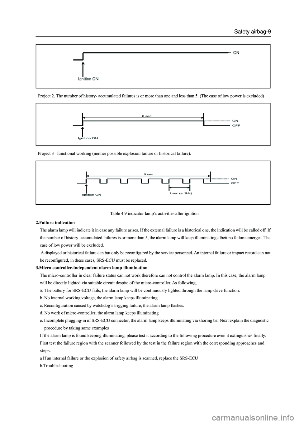
1. Bulb test
SRS-ECU will light the alarm lamp in order to test the bulb after working voltage is provided to it through the battery. The lamp
will flash for 6 times and then extinguish at 1HZ in the initial phase. The alarm lamp will keep illuminating after the working
voltage is provided in order to inform the driver’s system failures. The alarm lamp will keep illuminating for 6 seconds after the
ignition on and then be extinguished if the history-accumulated failures are less than five times. In the initial phase, SRS-ECU will
not prepare to test impact and stop release till the circuit is stable. Therefore, alarm lamp’s display manner will be one of
following projects in the initial phase. (Table 4.9).
Project 1. If the impact is recorded or the number of history accumulated failures is or more than 5,the alarm lamp will keep
illuminating, simultaneously, it will also keep illuminating if there is a possible explosion failure.
Page 379 of 425
Safety airbag-9
Project 3 functional working (neither possible explosion failure or historical failure).
Table 4.9 indicator lamp’s activities after ignition
2.Failure indication
The alarm lamp will indicate it in case any failure arises. If the external failure is a historical one, the indication will be called off. If
the number of history-accumulated failures is or more than 5, the alarm lamp will keep illuminating albeit no failure emerges. The
case of low power will be excluded.
A displayed or historical failure can but only be reconfigured by the service personnel. An internal failure or impact record can not
be reconfigured, in these cases, SRS-ECU must be replaced.
3.Micro controller-independent alarm lamp illumination
The micro-controller in clear failure status can not work therefore can not control the alarm lamp. In this case, the alarm lamp
will be directly lighted via suitable circuit despite of the micro-controller. As following,
The battery for SRS-ECU fails, the alarm lamp will be continuously lighted through the lamp drive function.
b. No internal working voltage, the alarm lamp keeps illuminating
c. Reconfiguration caused by watchdog’s trigging failure, the alarm lamp flashes.
d. No work of micro-controller, the alarm lamp keeps illuminating
e. Incomplete plugging-in of SRS-ECU connector, the alarm lamp keeps illuminating via shoring bar Next explain the diagnostic
procedure by taking some examples
If the alarm lamp is found keeping illuminating, please test it according to the following procedure even it extinguishes finally.
First test the failure region with the scanner followed by the test in the failure region with the corresponding approaches and
steps.
a If an internal failure or the explosion of safety airbag is scanned, replace the SRS-ECU
b.Troubleshooting Project 2. The number of history- accumulated failures is or more than one and less than 5. (The case of low power is excluded)
Page 381 of 425
Safety airbag-11
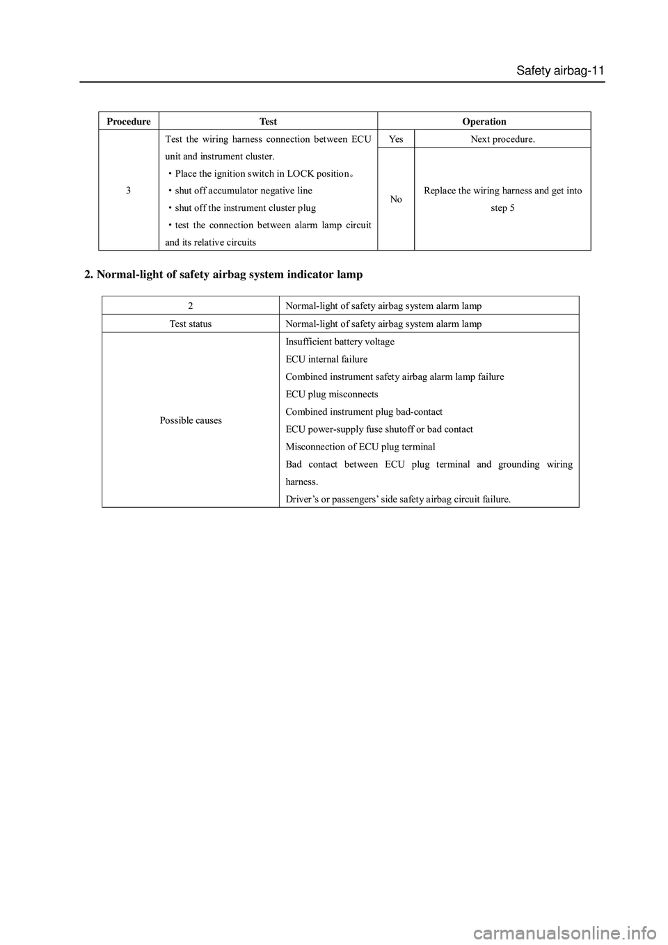
2. Normal-light of safety airbag system indicator lamp
2 Normal-light of safety airbag system alarm lamp
Test status Normal-light of safety airbag system alarm lamp
Possible causes Insufficient battery voltage
ECU internal failure
Combined instrument safety airbag alarm lamp failure
ECU plug misconnects
Combined instrument plug bad-contact
ECU power-supply fuse shutoff or bad contact
Misconnection of ECU plug terminal
Bad contact between ECU plug terminal and grounding wiring
harness.
Driver ’s or passengers’ side safety airbag circuit failure.
Procedure Te s t Operation
Yes Next procedure.
3 Test the wiring harness connection between ECU
unit and instrument cluster.
·Place the ignition switch in LOCK position。
·shut off accumulator negative line
·shut off the instrument cluster plug
·test the connection b etween alarm lamp circuit
and its relative circuits No Replace the wiring harness and get into
step 5
Page 382 of 425
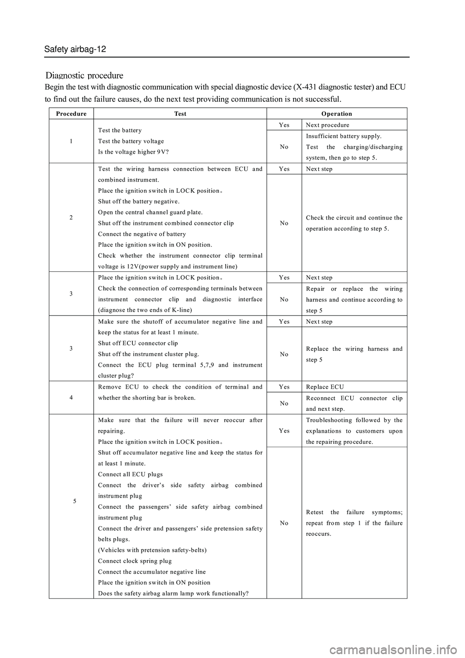
Safety airbag-12
Begin the test with diagnostic communication with special diagnostic device (X-431 diagnostic tester) and ECU
to find out the failure causes, do the next test providing communication is not successful.
Procedure Te s t Operation
Yes Next procedure
1 Test the battery
Test the battery voltage
Is the voltage higher 9V? No Insufficient battery supply.
Test the charging/discharging
system, then go to step 5.
Yes Next step
2 Test the wiring harness connection between ECU and
combined instrument.
Place the ignition switch in LO C K position。
Shut off the battery negative.
O pen the central channel guard plate.
Shut off the instrument combined connector clip
Connect the negative of battery
Place the ignition switch in ON position.
Check whether the instrument connector clip terminal
voltage is 12V(power supply and instrument line) No Check the circuit and continue the
operation according to step 5.
Yes Next step
3 Place the ignition switch in LO C K position。
Check the connection of corresponding terminals between
instrument connector clip and diagnostic interface
(diagnose the two ends of K-line) No Repair or replace the wiring
harness and continue according to
step 5
Yes Next step
3 Make sure the shutoff of accumulator negative line and
keep the status for at least 1 minute.
Shut off ECU connector clip
Shut off the instrument cluster plug.
Connect the ECU plug terminal 5,7,9 and instrument
cluster plug? No Replace the wiring harness and
step 5
Yes Replace ECU
4 Remove EC U to check the condition of term inal and
whether the shorting bar is broken.
No Reconnect EC U connector clip
and next step.
Yes Troubleshooting followed by the
explanations to customers upon
the repair ing pro ced ur e.
5
Make sure that the failure will never reoccur after
repairing.
Place the ignition switch in LO C K position。
Shut off accumulator negative line and keep the status for
at least 1 m in ute.
Connect all ECU plugs
Connect the driver’s side safety airbag combined
instrum ent p lug
Connect the passengers’ side safety airbag combined
instrum ent p lug
Connect the driver and passengers’ side pretension safety
belts plugs.
(Vehicles with pretension safety-b elts)
Connect clock spring plug
Connect the accumulator negative line
Place the ignition switch in ON position
Does the safety airbag alarm lamp work functionally? No Retest the failure symptoms;
repeat from step 1 if the failure
reoccurs.