stop start GREAT WALL HOVER 2006 Service Repair Manual
[x] Cancel search | Manufacturer: GREAT WALL, Model Year: 2006, Model line: HOVER, Model: GREAT WALL HOVER 2006Pages: 425, PDF Size: 26.05 MB
Page 11 of 425
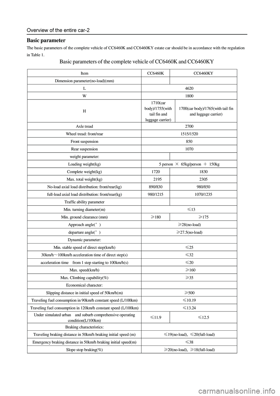
Basic parameter
The basic parameters of the complete vehicle of CC6460K and CC6460KY estate car should be in accordance with the regulation
in Table 1.
Basic parameters of the complete vehicle of CC6460K and CC6460KY
Item CC6460K CC6460KY
Dimension parameter(no-load)(mm)
L 4620
W 1800
H 1710(car
body)/1755(with
tail fin and
luggage carrier) 1700(car body)/1765(with tail fin
and luggage carrier)
Axle tread 2700
Wheel tread: front/rear 1515/1520
Front suspension 850
Rear suspension 1070
weight parameter:
Loading weight(kg) 5 person × 65kg/person + 150kg
Complete weight(kg) 1720 1830
Max. total weight(kg) 2195 2305
No-load axial load distribution: front/rear(kg) 890/830 980/850
full-load axial load distribution: front/rear(kg) 980/1215 1070/1235
Traffic ability parameter
Min. turning diameter(m) ≤13
Min. ground clearance (mm) ≥180 ≥175
Approach angle(°) ≥28(no-load)
departure angle(°) ≥27.5(no-load)
Dynamic parameter:
Min. stable speed of direct step(km/h) ≤25
30km/h~100km/h acceleration time of direct step(s) ≤32
acceleration time from 1 step starting to 100km/h(s) ≤20
Max. speed(km/h) ≥160
Max. Climbing capability(%) ≥35
Economical character:
Slipping distance in initial speed of 50km/h(m) ≥500
Traveling fuel consumption in 90km/h constant speed (L/100km) ≤10.19
Traveling fuel consumption in 120km/h constant speed (L/100km) ≤13.24
Under simulated urban and suburb comprehensive operating
condition(L/100km) ≤11.9 ≤12.5
Braking characteristics:
Traveling braking distance in 50km/h braking initial speed (m) ≤19(no-load), ≤20(full-load)
Emergency braking distance in 50km/h braking initial speed(m) ≤38
Slop e stop braking(%) ≥20(no-load), ≥18(full-load)
Page 17 of 425
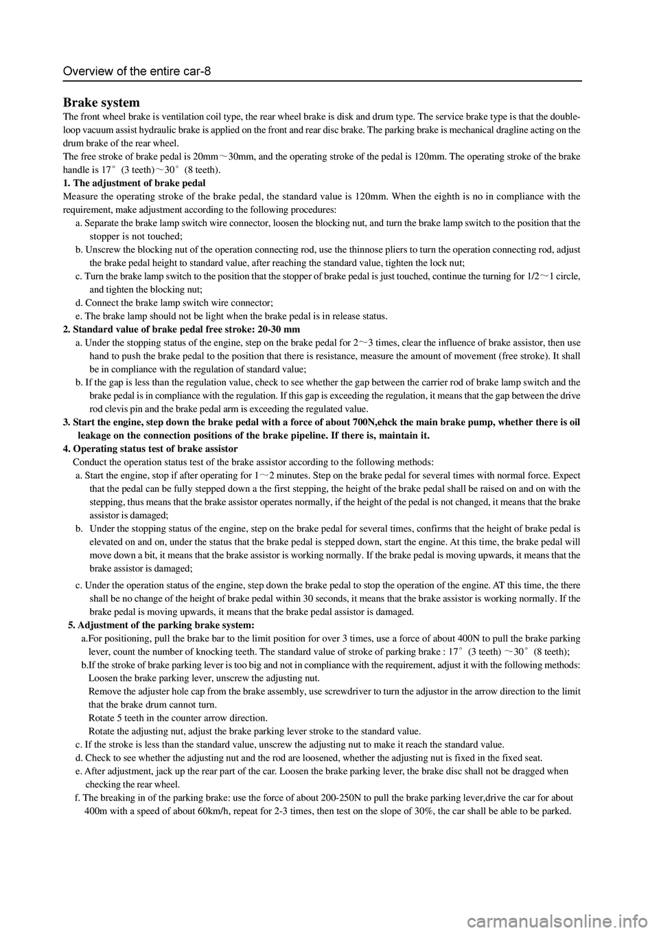
Brake system
The front wheel brake is ventilation coil type, the rear wheel brake is disk and drum type. The service brake type is that the double-
loop vacuum assist hydraulic brake is applied on the front and rear disc brake. The parking brake is mechanical dragline acting on the
drum brake of the rear wheel.
The free stroke of brake pedal is 20mm
30mm, and the operating stroke of the pedal is 120mm. The operating stroke of the brake
handle is 17
(3 teeth)30(8 teeth).
1. The adjustment of brake pedal
Measure the operating stroke of the brake pedal, the standard value is 120mm. When the eighth is no in compliance with the
requirement, make adjustment according to the following procedures:
a. Separate the brake lamp switch wire connector, loosen the blocking nut, and turn the brake lamp switch to the position that the
stopper is not touched;
b. Unscrew the blocking nut of the operation connecting rod, use the thinnose pliers to turn the operation connecting rod, adjust
the brake pedal height to standard value, after reaching the standard value, tighten the lock nut;
c. Turn the brake lamp switch to the position that the stopper of brake pedal is just touched, continue the turning for 1/2
1 circle,
and tighten the blocking nut;
d. Connect the brake lamp switch wire connector;
e. The brake lamp should not be light when the brake pedal is in release status.
2. Standard value of brake pedal free stroke: 20-30 mm
a. Under the stopping status of the engine, step on the brake pedal for 2
3 times, clear the influence of brake assistor, then use
hand to push the brake pedal to the position that there is resistance, measure the amount of movement (free stroke). It shall
be in compliance with the regulation of standard value;
b. If the gap is less than the regulation value, check to see whether the gap between the carrier rod of brake lamp switch and the
brake pedal is in compliance with the regulation. If this gap is exceeding the regulation, it means that the gap between the drive
rod clevis pin and the brake pedal arm is exceeding the regulated value.
3. Start the engine, step down the brake pedal with a force of about 700N,ehck the main brake pump, whether there is oil
leakage on the connection positions of the brake pipeline. If there is, maintain it.
4. Operating status test of brake assistor
Conduct the operation status test of the brake assistor according to the following methods:
a. Start the engine, stop if after operating for 1
2 minutes. Step on the brake pedal for several times with normal force. Expect
that the pedal can be fully stepped down a the first stepping, the height of the brake pedal shall be raised on and on with the
stepping, thus means that the brake assistor operates normally, if the height of the pedal is not changed, it means that the brake
assistor is damaged;
b. Under the stopping status of the engine, step on the brake pedal for several times, confirms that the height of brake pedal is
elevated on and on, under the status that the brake pedal is stepped down, start the engine. At this time, the brake pedal will
move down a bit, it means that the brake assistor is working normally. If the brake pedal is moving upwards, it means that the
brake assistor is damaged;
c. Under the operation status of the engine, step down the brake pedal to stop the operation of the engine. AT this time, the there
shall be no change of the height of brake pedal within 30 seconds, it means that the brake assistor is working normally. If the
brake pedal is moving upwards, it means that the brake pedal assistor is damaged.
5. Adjustment of the parking brake system:
a.For positioning, pull the brake bar to the limit position for over 3 times, use a force of about 400N to pull the brake parking
lever, count the number of knocking teeth. The standard value of stroke of parking brake : 17
(3 teeth) 30(8 teeth);
b.If the stroke of brake parking lever is too big and not in compliance with the requirement, adjust it with the following methods:
Loosen the brake parking lever, unscrew the adjusting nut.
Remove the adjuster hole cap from the brake assembly, use screwdriver to turn the adjustor in the arrow direction to the limit
that the brake drum cannot turn.
Rotate 5 teeth in the counter arrow direction.
Rotate the adjusting nut, adjust the brake parking lever stroke to the standard value.
c. If the stroke is less than the standard value, unscrew the adjusting nut to make it reach the standard value.
d. Check to see whether the adjusting nut and the rod are loosened, whether the adjusting nut is fixed in the fixed seat.
e. After adjustment, jack up the rear part of the car. Loosen the brake parking lever, the brake disc shall not be dragged when
checking the rear wheel.
f. The breaking in of the parking brake: use the force of about 200-250N to pull the brake parking lever,drive the car for about
400m with a speed of about 60km/h, repeat for 2-3 times, then test on the slope of 30%, the car shall be able to be parked.
Page 18 of 425
Overview of the entire car-9
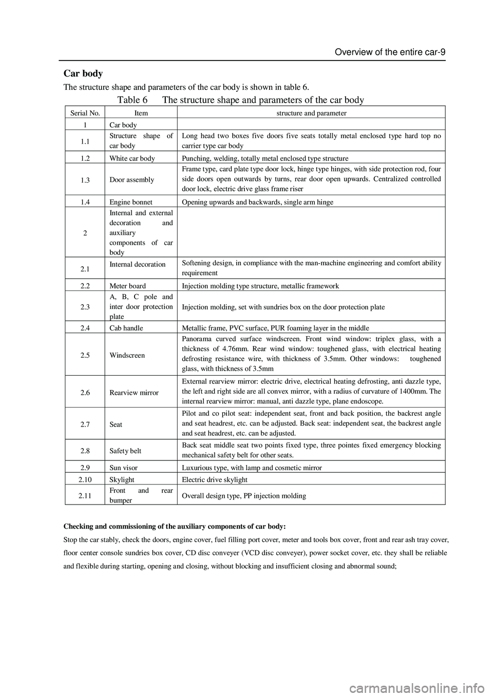
Car body
The structure shape and parameters of the car body is shown in table 6.
Table 6 The structure shape and parameters of the car body
Serial No. Item structure and parameter
1 Car body
1.1 Structure shap e of
car body Long head two boxes five doors five seats totally metal enclosed type hard top no
carrier t yp e car body
1.2 White car body Punching, welding, totally metal enclosed type structure
1.3 Door assembly Frame type, card plate type door lock, hinge type hinges, with side protection rod, four
side doors open outwards by turns, rear door open upwards. Centralized controlled
door lock, electric drive glass frame riser
1.4 Engine bonnet Opening upwards and backwards, single arm hinge
2 Int ernal and external
decoration and
auxiliary
components of car
body
2.1 Internal decoration Softening design, in compliance with the man-machine engineering and comfort ability
requirement
2.2 Meter board Injection molding type structure, metallic framework
2.3 A, B, C pole and
inter door protection
plate Injection molding, set with sundries box on the door protection plate
2.4 Cab handle Metallic frame, PVC surface, PUR foaming layer in the middle
2.5 Windscreen Panorama curved surface windscreen. Front wind window: triplex glass, with a
thickness of 4.76mm. Rear wind window: toughened glass, with electrical heating
defrosting resistance wire, with thickness of 3.5mm. Other windows: toughened
glass, with thickness of 3.5mm
2.6 Rearview mirror External rearview mirror: electric drive, electrical heating defrosting, anti dazzle type,
the left and right side are all convex mirror, with a radius of curvature of 1400mm. The
internal rearview mirror: manual, anti dazzle type, plane endoscope.
2.7 Seat Pilot and co pilot seat: independent seat, front and back position, the backrest angle
and seat headrest, etc. can be adjusted. Back seat: independent seat, the backrest angle
and seat headrest, etc. can be adjusted.
2.8 Safety belt Back seat middle seat two points fixed type, three pointes fixed emergency blocking
mechanical safety belt for other seats.
2.9 Sun visor Luxurious type, with lamp and cosmetic mirror
2.10 Skylight Electric drive skylight
2.11 Front and rear
bumper Overall design type, PP injection molding
Checking and commissioning of the auxiliary components of car body:
Stop the car stably, check the doors, engine cover, fuel filling port cover, meter and tools box cover, front and rear ash tray cover,
floor center console sundries box cover, CD disc conveyer (VCD disc conveyer), power socket cover, etc. they shall be reliable
and flexible during starting, opening and closing, without blocking and insufficient closing and abnormal sound;
Page 20 of 425
Overview of the entire car-11
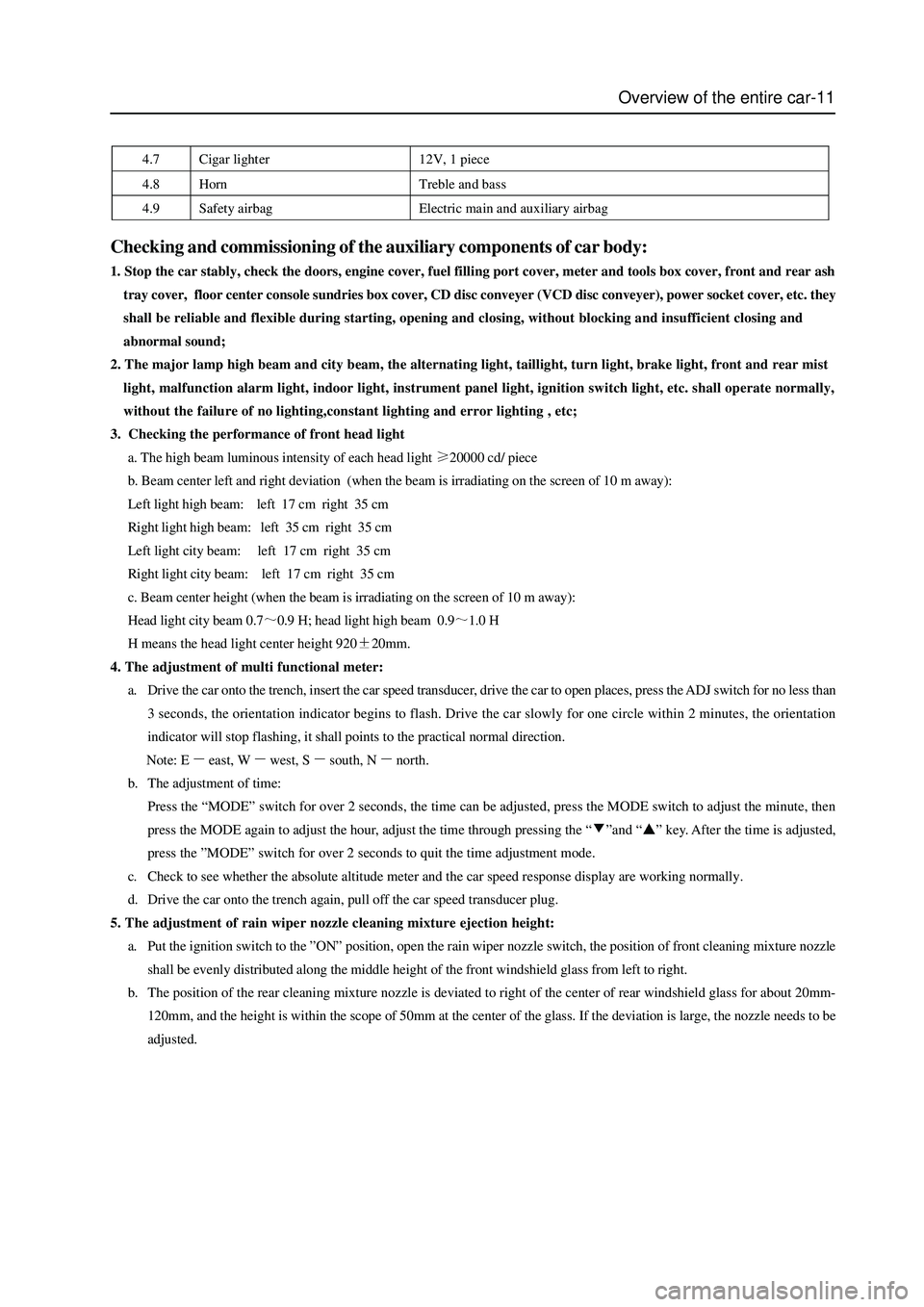
4.7 Cigar lighter 12V, 1 piece
4.8 Horn Treble and bass
4.9 Safety airbag Electric main and auxiliary airbag
Checking and commissioning of the auxiliary components of car body:
1. Stop the car stably, check the doors, engine cover, fuel filling port cover, meter and tools box cover, front and rear ash
tray cover, floor center console sundries box cover, CD disc conveyer (VCD disc conveyer), power socket cover, etc. they
shall be reliable and flexible during starting, opening and closing, without blocking and insufficient closing and
abnormal sound;
2. The major lamp high beam and city beam, the alternating light, taillight, turn light, brake light, front and rear mist
light, malfunction alarm light, indoor light, instrument panel light, ignition switch light, etc. shall operate normally,
without the failure of no lighting,constant lighting and error lighting , etc;
3. Checking the performance of front head light
a. The high beam luminous intensity of each head light
20000 cd/ piece
b. Beam center left and right deviation (when the beam is irradiating on the screen of 10 m away):
Left light high beam: left 17 cm right 35 cm
Right light high beam: left 35 cm right 35 cm
Left light city beam: left 17 cm right 35 cm
Right light city beam: left 17 cm right 35 cm
c. Beam center height (when the beam is irradiating on the screen of 10 m away):
Head light city beam 0.7
0.9 H; head light high beam 0.91.0 H
H means the head light center height 920
20mm.
4. The adjustment of multi functional meter:
a. Drive the car onto the trench, insert the car speed transducer, drive the car to open places, press the ADJ switch for no less than
3 seconds, the orientation indicator begins to flash. Drive the car slowly for one circle within 2 minutes, the orientation
indicator will stop flashing, it shall points to the practical normal direction.
Note: E
east, Wwest, Ssouth, Nnorth.
b. The adjustment of time:
Press the “MODE” switch for over 2 seconds, the time can be adjusted, press the MODE switch to adjust the minute, then
press the MODE again to adjust the hour, adjust the time through pressing the “
”and “” key. After the time is adjusted,
press the ”MODE” switch for over 2 seconds to quit the time adjustment mode.
c. Check to see whether the absolute altitude meter and the car speed response display are working normally.
d. Drive the car onto the trench again, pull off the car speed transducer plug.
5. The adjustment of rain wiper nozzle cleaning mixture ejection height:
a. Put the ignition switch to the ”ON” position, open the rain wiper nozzle switch, the position of front cleaning mixture nozzle
shall be evenly distributed along the middle height of the front windshield glass from left to right.
b. The position of the rear cleaning mixture nozzle is deviated to right of the center of rear windshield glass for about 20mm-
120mm, and the height is within the scope of 50mm at the center of the glass. If the deviation is large, the nozzle needs to be
adjusted.
Page 63 of 425
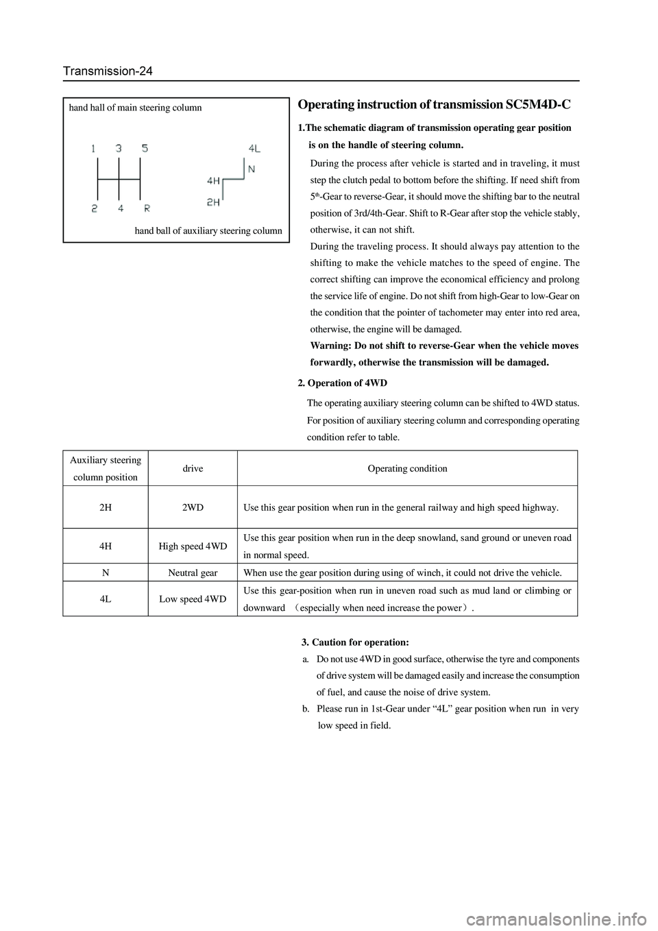
2. Operation of 4WD
The operating auxiliary steering column can be shifted to 4WD status.
For position of auxiliary steering column and corresponding operating
condition refer to table.
3. Caution for operation:
a. Do not use 4WD in good surface, otherwise the tyre and components
of drive system will be damaged easily and increase the consumption
of fuel, and cause the noise of drive system.
b. Please run in 1st-Gear under “4L” gear position when run in very
low speed in field.
Operating instruction of transmission SC5M4D-C
1.The schematic diagram of transmission operating gear position
is on the handle of steering column.
During the process after vehicle is started and in traveling, it must
step the clutch pedal to bottom before the shifting. If need shift from
5
th-Gear to reverse-Gear, it should move the shifting bar to the neutral
position of 3rd/4th-Gear. Shift to R-Gear after stop the vehicle stably,
otherwise, it can not shift.
During the traveling process. It should always pay attention to the
shifting to make the vehicle matches to the speed of engine. The
correct shifting can improve the economical efficiency and prolong
the service life of engine. Do not shift from high-Gear to low-Gear on
the condition that the pointer of tachometer may enter into red area,
otherwise, the engine will be damaged.
Warning: Do not shift to reverse-Gear when the vehicle moves
forwardly, otherwise the transmission will be damaged.
hand hall of main steering column
hand ball of auxiliary steering column
Auxiliary steering
column position drive Operating condition
2H 2WD Use this gear position when run in the general railway and high speed highway.
4H High speed 4WD Use this gear position when run in the deep snowland, sand ground or uneven road
in normal speed.
N Neutral gear When use the gear position during using of winch, it could not drive the vehicle.
4L Low speed 4WD Use this gear-position when run in uneven road such as mud land or climbing or
downward (especially when need increas e the power).
Page 265 of 425
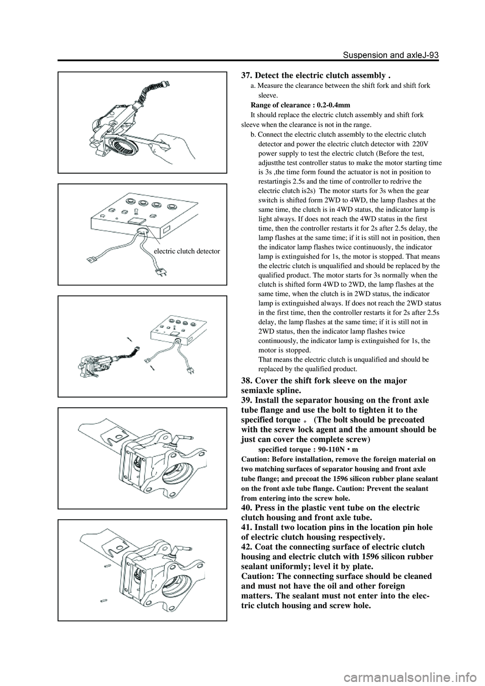
electric clutch detector
37. Detect the electric clutch assembly .
a. Measure the clearance between the shift fork and shift fork
sleeve.
Range of clearance : 0.2-0.4mm
It should replace the electric clutch assembly and shift fork
sleeve when the clearance is not in the range.
b. Connect the electric clutch assembly to the electric clutch
detector and power the electric clutch detector with220V
power supply to test the electric clutch (Before the test,
adjustthe test controller status to make the motor starting time
is 3s ,the time form found the actuator is not in position to
restartingis 2.5s and the time of controller to redrive the
electric clutch is2s) The motor starts for 3s when the gear
switch is shifted form 2WD to 4WD, the lamp flashes at the
same time, the clutch is in 4WD status, the indicator lamp is
light always. If does not reach the 4WD status in the first
time, then the controller restarts it for 2s after 2.5s delay, the
lamp flashes at the same time; if it is still not in position, then
the indicator lamp flashes twice continuously, the indicator
lamp is extinguished for 1s, the motor is stopped. That means
the electric clutch is unqualified and should be replaced by the
qualified product. The motor starts for 3s normally when the
clutch is shifted form 4WD to 2WD, the lamp flashes at the
same time, when the clutch is in 2WD status, the indicator
lamp is extinguished always. If does not reach the 2WD status
in the first time, then the controller restarts it for 2s after 2.5s
delay, the lamp flashes at the same time; if it is still not in
2WD status, then the indicator lamp flashes twice
continuously, the indicator lamp is extinguished for 1s, the
motor is stopped.
That means the electric clutch is unqualified and should be
replaced by the qualified product.
38. Cover the shift fork sleeve on the major
semiaxle spline.
39. Install the separator housing on the front axle
tube flange and use the bolt to tighten it to the
specified torque
(The bolt should be precoated
with the screw lock agent and the amount should be
just can cover the complete screw)
specified torque : 90-110Nm
Caution: Before installation, remove the foreign material on
two matching surfaces of separator housing and front axle
tube flange; and precoat the 1596 silicon rubber plane sealant
on the front axle tube flange. Caution: Prevent the sealant
from entering into the screw hole.
40. Press in the plastic vent tube on the electric
clutch housing and front axle tube.
41. Install two location pins in the location pin hole
of electric clutch housing respectively.
42. Coat the connecting surface of electric clutch
housing and electric clutch with 1596 silicon rubber
sealant uniformly; level it by plate.
Caution: The connecting surface should be cleaned
and must not have the oil and other foreign
matters. The sealant must not enter into the elec-
tric clutch housing and screw hole.
Page 367 of 425
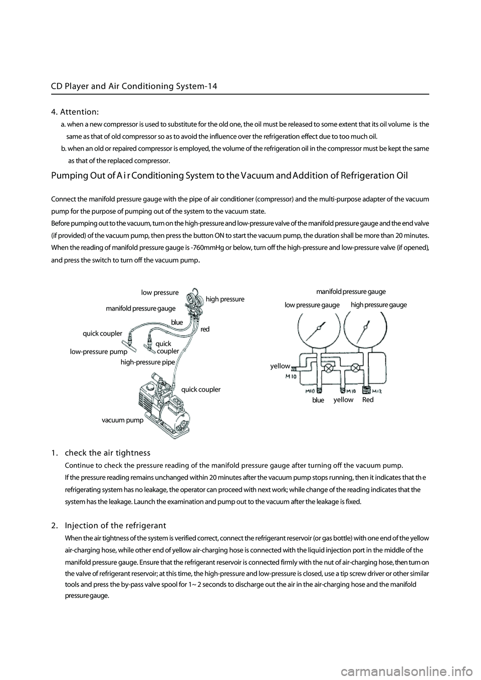
CD Player and Air Conditioning System-14
Pumping Out of A i r Conditioning System to the Vacuum and Addition of Refrigeration Oil
Connect the manifold pressure gauge with the pipe of air conditioner (compressor) and the multi-purpose adapter of the vacuum
pump for the purpose of pumping out of the system to the vacuum state.
Before pumping out to the vacuum, turn on the high-pressure and low-pressure valve of the
manifold pressure gauge and the end valve
(if provided) of the vacuum pump, then press the button ON to start the vacuum pump, the duration shall be more than 20 minutes
.
When the reading of manifold pressure gauge is -760mmHg or below, turn off the high-pressure and low-pressure valve (if opened)
,
and press the switch to turn off the vacuum pum
p.
1 . check the air tightness
Continue to check the pressure reading of the manifold pressure gauge after turning off the vacuum pump.
If the pressure reading remains unchanged within 20 minutes after the vacuum pump stops running, then it indicates that th
e
refrigerating system has no leakage, the operator can proceed with next work; while change of the reading indicates that the
system has the leakage. Launch the examination and pump out to the vacuum after the leakage is fixed.
2 . Injection of the refrigerant
When the air tightness of the system is verified correct, connect the refrigerant reservoir (or gas bottle) with one end of the yellow
a ir-charging hose, while other end of yellow air-charging hose is connected with the liquid injection port in the middle of the
manifold pressure gauge. Ensure that the refrigerant reservoir is connected firmly with the nut of air-charging hose, then turn on
the valve of refrigerant reservoir; at this time, the high-pressure and low-pressure is closed, use a tip screw driver or other
similar
tools and press the by-pass valve spool for 1~ 2 seconds to discharge out the air in the air-charging hose and the manifold
pressure gauge.
low p ressure
high pressure
manifold pressure gauge
quick coupler
l ow-pressure pump
high-pressure pipe
quick coupler
quick
coupler
red
blue
vacuum pum
p
manifold pressure gauge
low pressure gauge high
pressure gauge
Red
blue
yellow
yellow
4. Attention:
a. when a new compressor is used to substitute for the old one, the oil must be released to some extent that its oil volume is the
same as that of old compressor so as to avoid the influence over the refrigeration effect due to too much oil.
b. when an old or repaired compressor is employed, the volume of the refrigeration oil in the compressor must be kept the sam
e
as that of the replaced
compressor.
Page 368 of 425
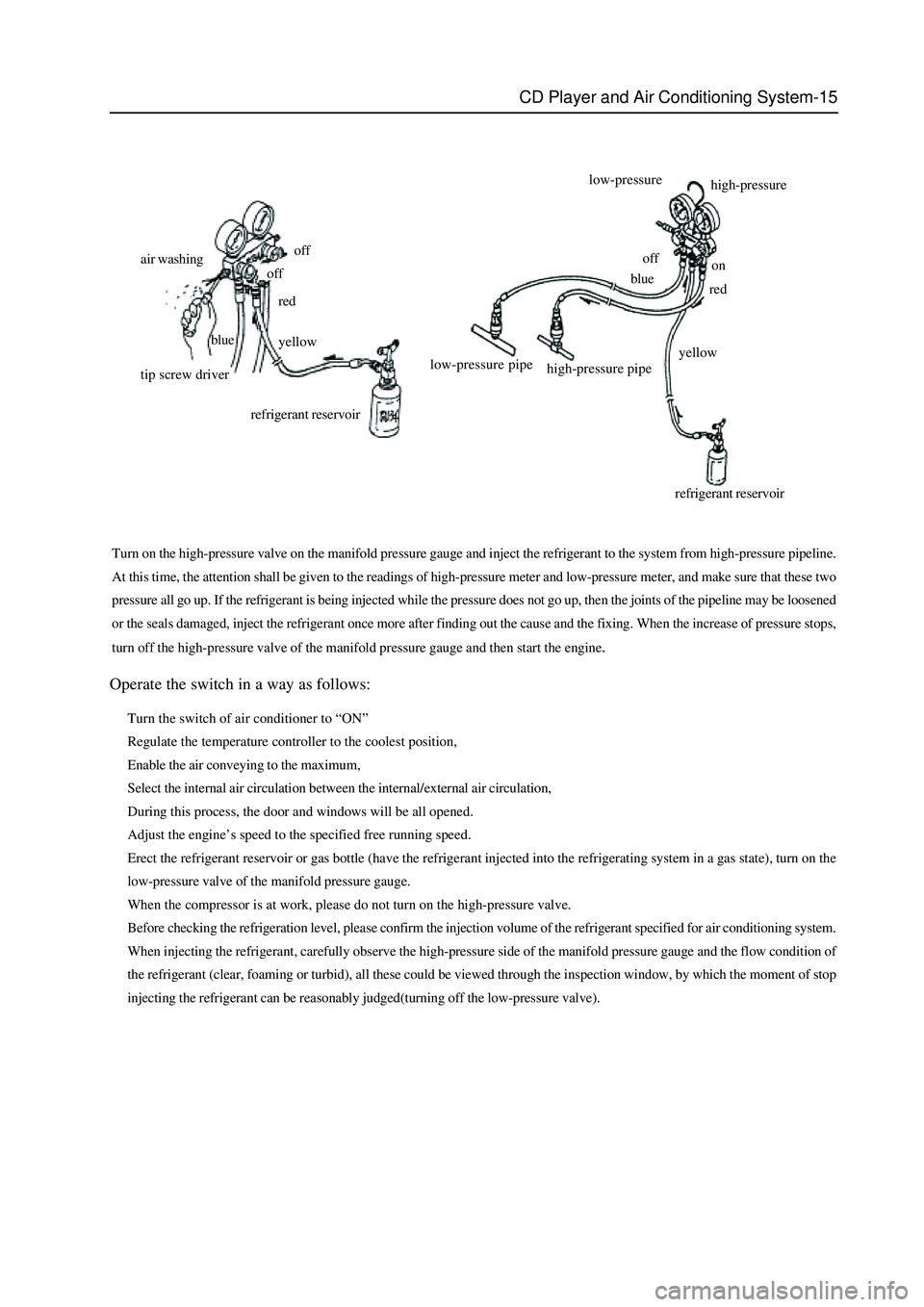
CD Player and Air Conditioning System-15
Turn on the high-pressure valve on the manifold pressure gauge and inject the refrigerant to the system from high-pressure pipeline.
At this time, the attention shall be given to the readings of high-pressure meter and low-pressure meter, and make sure that these two
pressure all go up. If the refrigerant is being injected while the pressure does not go up, then the joints of the pipeline may be loosened
or the seals damaged, inject the refrigerant once more after finding out the cause and the fixing. When the increase of pressure stops,
turn off the high-pressure valve of the manifold pressure gauge and then start the engine
.
Operate the switch in a way as follows:
Turn the switch of air conditioner to “ON”
Regulate the temperature controller to the coolest position,
Enable the air conveying to the maximum,
Select the internal air circulation between the internal/external air circulation,
During this process, the door and windows will be all opened.
Adjust the engine’s speed to the specified free running speed.
Erect the refrigerant reservoir or gas bottle (have the refrigerant injected into the refrigerating system in a gas state), turn on the
low-pressure valve of the manifold pressure gauge.
When the compressor is at work, please do not turn on the high-pressure valve.
Before checking the refrigeration level, please confirm the injection volume of the refrigerant specified for air conditioning system.
When injecting the refrigerant, carefully observe the high-pressure side of the manifold pressure gauge and the flow condition of
the refrigerant (clear, foaming or turbid), all these could be viewed through the inspection window, by which the moment of stop
injecting the refrigerant can be reasonably judged(turning off the low-pressure valve).
air washingoff
off
tip screw driverred
yellow blue
refrigerant reservoirhigh-pressure low-pressure
off
low-pressure pipe
high-pressure pipe
refrigerant reservoiryellowred blueon