fuse HONDA ACCORD HYBRID 2014 9.G Owners Manual
[x] Cancel search | Manufacturer: HONDA, Model Year: 2014, Model line: ACCORD HYBRID, Model: HONDA ACCORD HYBRID 2014 9.GPages: 561, PDF Size: 20.3 MB
Page 2 of 561
Contents
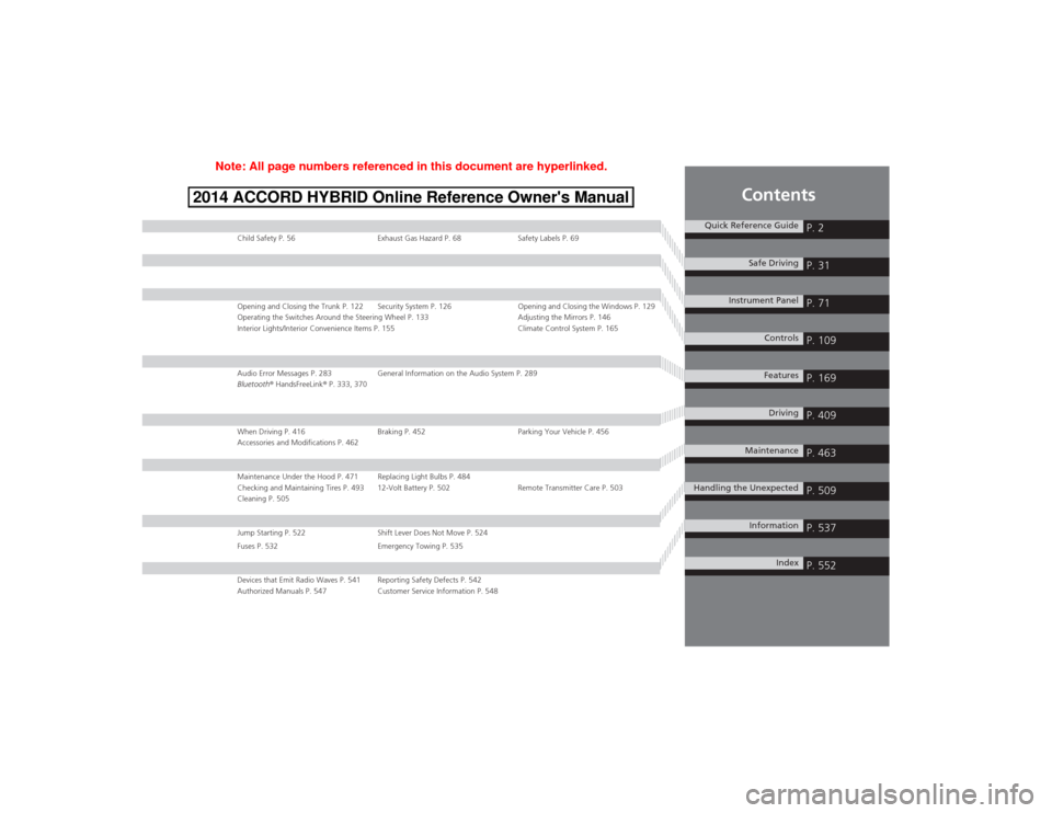
Child Safety P. 56 Exhaust Gas Hazard P. 68 Safety Labels P. 69
Opening and Closing the Trunk P. 122 Security System P. 126 Opening and Closing the Windows P. 129
Operating the Switches Around the Steering Wheel P. 133 Adjusting the Mirrors P. 146
Interior Lights/Interior Convenience Items P. 155 Climate Control System P. 165
Audio Error Messages P. 283 General Information on the Audio System P. 289
Bluetooth® HandsFreeLink ® P. 333, 370
When Driving P. 416 Braking P. 452 Parking Your Vehicle P. 456
Accessories and Modifications P. 462
Maintenance Under the Hood P. 471 Replacing Light Bulbs P. 484
Checking and Maintaining Tires P. 493 12-Volt Battery P. 502 Remote Transmitter Care P. 503
Cleaning P. 505
Jump Starting P. 522 Shift Lever Does Not Move P. 524
Fuses P. 532 Emergency Towing P. 535
Devices that Emit Radio Waves P. 541 Reporting Safety Defects P. 542
Authorized Manuals P. 547 Customer Service Information P. 548
Quick Reference GuideP. 2
Safe DrivingP. 31
Instrument PanelP. 71
ControlsP. 109
FeaturesP. 169
DrivingP. 409
MaintenanceP. 463
Handling the UnexpectedP. 509
InformationP. 537
IndexP. 552
Note: All page numbers referenced in this document are hyperlinked.
2014 ACCORD HYBRID Online Reference Owner's Manual
Page 5 of 561
Visual Index
4
Quick Reference Guide
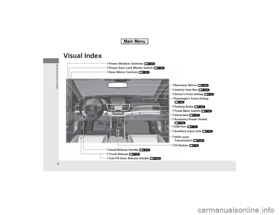
❙Door Mirror Controls (P 147)
❙Passenger's Front Airbag
(P 46)
❙Parking Brake (P 452)
❙Glove Box (P 157)
❙Rearview Mirror (P 146)
❙Hood Release Handle (P 472)
❙Power Door Lock Master Switch (P 120)
❙Power Window Switches (P 129)
❙Interior Fuse Box (P 533)
❙Driver's Front Airbag (P 46)
❙Trunk Main Switch (P 124)
❙Fuel Fill Door Release Handle (P 460)
❙Trunk Release (P 122)
❙Shift Lever Transmission (P 420)
❙USB Port
(P 171)
❙Auxiliary Input Jack (P 172)
❙Accessory Power Socket
(P 160)
❙EV Button (P 10)
Main Menu
Page 27 of 561
26
Quick Reference Guide
Handling the Unexpected (P 509)
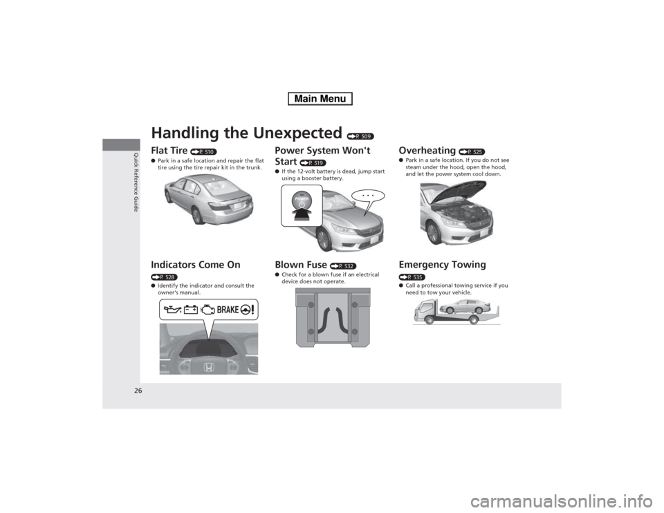
Flat Tire (P 510)
● Park in a safe location and repair the flat
tire using the tire repair kit in the trunk.
Indicators Come On
(P 528) ● Identify the indicator and consult the
owner's manual.
Power System Won't Start (P 519)
● If the 12-volt battery is dead, jump start
using a booster battery.
Blown Fuse (P 532)
● Check for a blown fuse if an electrical
device does not operate.Overheating (P 525)
● Park in a safe location. If you do not see
steam under the hood, open the hood,
and let the power system cool down.
Emergency Towing
(P 535) ● Call a professional towing service if you
need to tow your vehicle.
Main Menu
Page 454 of 561
453
uuBrakinguBrake System
Driving
Your vehicle is equipped with disc brakes at all four wheels. The brake assist system
increases the stopping force when you depress the brake pedal hard in an
emergency situation. The anti-lock brake system (ABS) helps you retain steering
control when braking very hard.2 Brake Assist System P. 455
2 Anti-lock Brake System (ABS) P. 454
■Foot Brake1Foot Brake
Check the brakes after driving through deep water,
or if there is a buildup of road surface water. If
necessary, dry the brakes by lightly depressing the
pedal several times.
If you hear a continuous metallic friction sound when
applying the brakes, the brake pads need to be
replaced. Have your vehicle checked by a dealer.
Constantly using the brake pedal while going down a
long hill builds up heat, which reduces the brake
effectiveness. Apply regenerative braking by taking
your foot off the accelerator pedal and shifting to .
Do not rest your foot on the brake pedal while
driving, as it will lightly apply the brakes and cause
them to lose effectiveness over time and reduce pad
life. It will also confuse drivers behind you.
When you depress the brake pedal, you may hear a
motor sound coming from the engine compartment
while the brake system activates. This is normal.
B
Main MenuTable of Contents
Page 463 of 561
462
Driving
Accessories and Modifications
Accessories
When installing accessories, check the following: •Do not install accessories on the windshield. They can obstruct your view and
delay your reaction to driving conditions.
• Do not install accessories over areas marked SRS AIRBAG, on the sides or backs
of the front seats, on front or side pillars, or near the side windows.
Accessories installed in these areas may interfere with proper operation of the
vehicle’s airbags or may be propelled into you or another occupant if the airbags
deploy.
• Be sure electronic accessories do not overload electrical circuits or interfere with
proper operation of your vehicle. 2 Fuses P. 532
• Before installing any electronic accessory, have the installer contact a dealer for
assistance. If possible, have a dealer inspect the final installation.
Modifications
Do not modify your vehicle or use non-Honda components that can affect its
handling, stability, and reliability.
Overall vehicle performance can be affected. Always make sure all equipment is
properly installed and maintained, and that it meets federal, state, province,
territory, and local regulations.
1Accessories and Modifications
Honda Genuine accessories are recommended to
ensure proper operation on your vehicle.
3WARNING
Improper accessories or modifications can
affect your vehicle's handling, stability, and
performance, and cause a crash in which
you can be seriously hurt or killed.
Follow all instruction s in this owner's
manual regarding accessories and
modifications.
Main MenuTable of Contents
Page 510 of 561
509
Handling the UnexpectedThis chapter explains how to h andle unexpected troubles.
If a Tire Goes Flat
Temporarily Repairing a Flat Tire....... 510
Power System Won’t Start Checking the Procedure ................... 519
If the Smart Entry Remote Battery is
Weak ..........................................520
Power System Off ............................ 521
Jump Starting .................................... 522
Shift Lever Does Not Move .............. 524Overheating
How to Handle Overheating............. 525
Indicator, Coming On/Blinking If the Low Oil Pressure Indicator Comes
On ............................................. 528
If the 12-Volt Battery Charging System Indicator Comes On ....................... 528
If the Malfunction Indicator Lamp Comes On or Blinks ................................... 529
If the Brake System Indicator (Red)
Comes On .................................. 530 If the Electric Power Steering (EPS) System
Indicator Comes On............................ 530
If the Low Tire Pressure/TPMS Indicator Comes On or Blinks ....................... 531
Fuses Fuse Locations ................................. 532
Inspecting and Changing Fuses ........ 534
Emergency Towing ........................... 535
Main Menu
Page 520 of 561
519
Handling the Unexpected
Power System Won’t Start
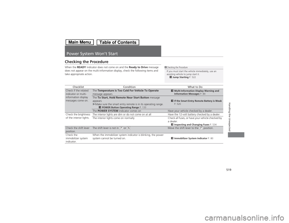
Checking the Procedure When the READY indicator does not come on and the Ready to Drive message
does not appear on the multi-information display, check the following items and
take appropriate action.
ChecklistConditionWhat to DoCheck if the related
indicator or multi- information display
messages come on.The Temperature is Too Cold For Vehicle To Operate
message appears2 Multi-Information Display Warning and
Information Messages P. 84
The To Start, Hold Remote Near Start Button message
appears
uMake sure the smart entry remote is in its operating range. 2POWER Button Operating Range P. 1332If the Smart Entry Remote Battery is Weak
P. 520
The POWER SYSTEM indicator comes onHave your vehicle checked by a dealer.
Check the brightness
of the interior lights. The interior lights are dim or do not come on at all Have the 12-volt battery checked by a dealer.
The interior lights come on normally Check all fuses, or have your vehicle checked by
a dealer.2Inspecting and Changing Fuses P. 534
Check the shift lever
position.The shift lever is not in (P or (NMove the shift lever to the (P position.
Check the
immobilizer system indicator. When the immobilizer system indicator is blinking, the power
system cannot be turned on.
2
Immobilizer System Indicator P. 80
1Checking the Procedure
If you must start the vehicle immediately, use an
assisting vehicle to jump start it.
2 Jump Starting P. 522
Main MenuTable of Contents
Page 533 of 561
532
Handling the Unexpected
Fuses
Fuse Locations
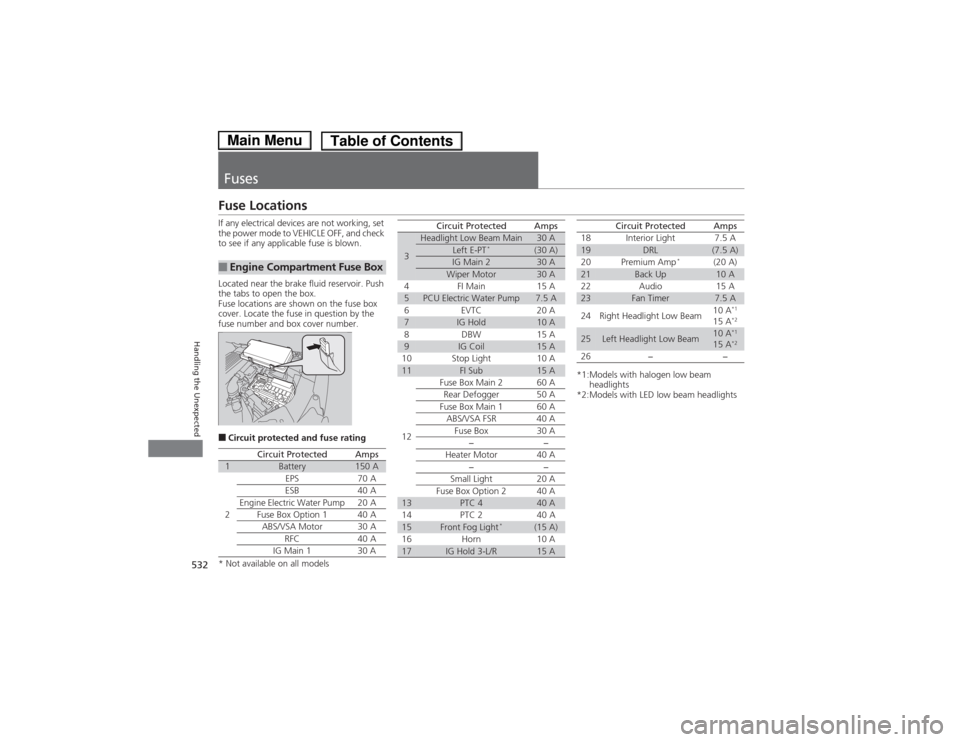
If any electrical devices are not working, set
the power mode to VEHICLE OFF, and check
to see if any applicable fuse is blown.
Located near the brake fluid reservoir. Push
the tabs to open the box.
Fuse locations are shown on the fuse box
cover. Locate the fuse in question by the
fuse number and box cover number. ■Circuit protected and fuse rating
■Engine Compartment Fuse Box
Circuit ProtectedAmps1Battery150 A
2
EPS70 A
ESB 40 A
Engine Electric Water Pump20 A
Fuse Box Option 1 40 A
ABS/VSA Motor30 A
RFC 40 A
IG Main 1 30 A
3
Headlight Low Beam Main30 ALeft E-PT *(30 A)IG Main 230 AWiper Motor30 A
4 FI Main 15 A
5PCU Electric Water Pump7.5 A
6E VTC 2 0A
7IG Hold10 A
8 DBW 15 A
9IG Coil15 A
10 Stop Light 10 A
11FI Sub15 A
12 Fuse Box Main 2 60 A
Rear Defogger 50 A
Fuse Box Main 1 60 A ABS/VSA FSR 40 A
Fuse Box 30 A −−
Heater Motor 40 A −−
Small Light 20 A
Fuse Box Option 2 40 A
13PTC 440 A
14 PTC 2 40 A
15Front Fog Light *(15 A)
16 Horn 10 A
17IG Hold 3-L/R15 A
Circuit ProtectedAmps
*1:Models with halogen low beam headlights
*2:Models with LED low beam headlights 18 Interior Light 7.5 A
19DRL(7.5 A)
20 Premium Amp *
(20 A)
21Back Up10 A
22 Audio 15 A
23Fan Timer7.5 A
24 Right Headlight Low Beam 10 A
*1
15 A *2
25Left Headlight Low Beam10 A*1
15 A *2
26 − −
Circuit ProtectedAmps
* Not available on all models
Main MenuTable of Contents
Page 534 of 561
533
uuFusesuFuse Locations
Handling the Unexpected
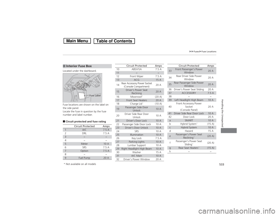
Located under the dashboard.
Fuse locations are shown on the label on
the side panel.
Locate the fuse in question by the fuse
number and label number. ■Circuit protected and fuse rating
■Interior Fuse Box
Fuse Label
Circuit ProtectedAmps1A/C7.5 A2DRL7.5 A3−−4−−5Meter10 A6SRS7.5 A7Option7.5 A8−−9Fuel Pump20 A
10ABS/VSA7.5 A11−−12Front Wiper7.5 A13ACG15 A
14Rear Accessory Power Socket
(Console Compartment)20 A
15Driver’s Power Seat Reclining20 A
16Moonroof *(20 A)17Front Seat Heaters20 A18Charge Lid
*(10 A)
19Passenger Side Door
Unlock10 A
20Driver Side Rear Door Unlock10 A
21Driver’s Door Lock10 A22Passenger Side Door Lock10 A23Driver’s Door Unlock10 A24SRS10 A25Illumination10 A26Key Lock7.5 A27Parking Lights10 A28Lumbar Support10 A29Right Headlight High Beam10 A30Washer15 A31A/C Main10 A32Driver’s Power Window20 A
Circuit ProtectedAmps
33Front Passenger’s Power Window20 A
34Rear Driver Side Power Window20 A
35Rear Passenger Side Power
Window20 A
36Driver’s Power Seat Sliding20 A37ACCESSORY7.5 A38−−39Left Headlight High Beam10 A
40Front Accessory Power Socket
(Console Panel)20 A
41Driver Side Rear Door Lock10 A42Door Lock20 AaSMART10 AbHybrid System *(15 A)cHybrid System10 AdHazard15 A
ePassenger's Power Seat
Reclining *(20 A)
fPassenger's Power Seat
Sliding*(20 A)
gRear Seat Heaters
*(15 A)h−−
Circuit ProtectedAmps
* Not available on all models
Main MenuTable of Contents
Page 535 of 561
534
uuFusesuInspecting and Changing Fuses
Handling the Unexpected
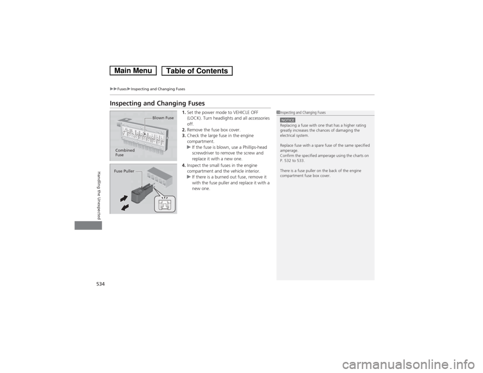
Inspecting and Changing Fuses1.Set the power mode to VEHICLE OFF
(LOCK). Turn headlights and all accessories off.
2. Remove the fuse box cover.
3. Check the large fuse in the engine compartment.
uIf the fuse is blown, use a Phillips-head
screwdriver to remove the screw and
replace it with a new one.
4. Inspect the small fuses in the engine
compartment and the vehicle interior.
uIf there is a burned out fuse, remove it
with the fuse puller and replace it with a
new one.
1Inspecting and Changing Fuses
NOTICEReplacing a fuse with one that has a higher rating
greatly increases the chances of damaging the
electrical system.
Replace fuse with a spare fuse of the same specified
amperage.
Confirm the specified amperage using the charts on
P. 532 to 533.
There is a fuse puller on the back of the engine compartment fuse box cover.
Combined
Fuse Blown Fuse
Fuse Puller
Main MenuTable of Contents