Gas HONDA CIVIC 1996 6.G Workshop Manual
[x] Cancel search | Manufacturer: HONDA, Model Year: 1996, Model line: CIVIC, Model: HONDA CIVIC 1996 6.GPages: 2189, PDF Size: 69.39 MB
Page 1124 of 2189
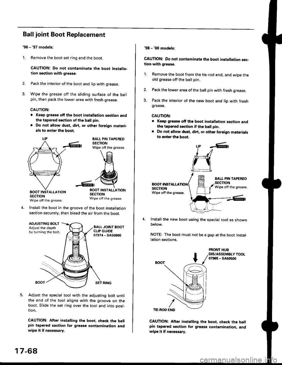
Ball joint Boot Replacement
'96 - '97 models:
1. Remove the boot set ring and the boot.
CAUTION: Do not contaminate the boot installa.tion section with grsase.
2. Pack the interior of the boot and lip with grease.
3. Wipe the grease off the sliding surface of the ballpin, then pack the lower area with fresh grease.
CAUTION:
. Keep grease off the boot installation seciion andthe tapered s€ction ot the ball pin.
. Do not allow dust, dirt, or oth6r foreign materi-
als to 6nt8r the boot.
LIPEALL PIN TAPEREDSECTIONWipe off the grease.
INSTALLATION
SECTIONWipe off the grease.
Install the boot in the groove of the boot installation
section securely, then bleed the air from the boot.
-6lrBOOTSECTIONWipe off the grease
4.
ADJUSTING BOLTAdjust the depthby turning the bolt.
SET RING
Adjust the special tool with the adjusting bolt untilthe end of the tool aligns with the groove on theboot. Slide the set ring over the tool and into posi-
UOn.
CAUTION: After installing the boot, qhsck the ballpin tapered section for grease contamination andwipe it it necGsary.
17-68
'98 - '00 models:
CAUTION: Do not contaminato the boot installation sec-tion with grease.
1. Remove the boot from the tie-rod end, and wiDe theold grease off the ball pin.
2. Pack the lower area ofthe ball pin with fresh grease.
3. Pack the interior of the new boot and liD with freshgrease.
CAUTION:
. Keop groasc ott tho boot installalion sestion andth. iapored s.ction if th€ ball pin.
. Do not allow dust. dirt, or other foreign materials
to entor tho boot.
BOOT INSTALLASECTIONWipe off the gr€ase,
Install the new boot using the special tool as shownbelow.
NOTE: The boot must not be a gap atthe boot installation sections.
LtP .6r
J_/
ru
CAUTION: Aftor installing the boot, chock the batlpin tapgred section tor grgase cortamination. andwipe it it n€ces3ary.
FRONT HUBDIS/ASSEMBLY TOOL07965 - SA5o500
Page 1142 of 2189
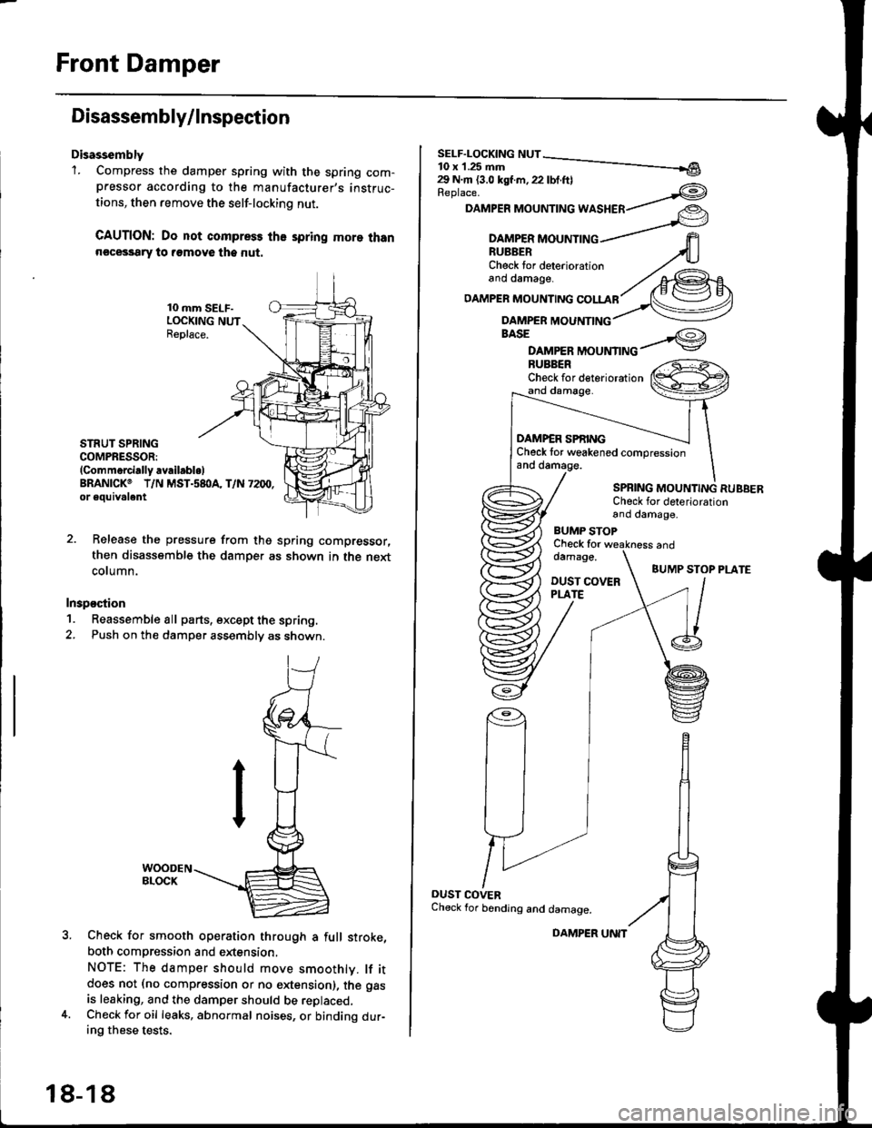
Front Damper
Disassembly/lnspection
Disassembly'1. Compress the damper spring with the spring com-pressor according to the manufacturer,s instruc-
tions, then remove the self-lockino nut.
CAUTION: Do not compress the spring more thann€cessary to remove the nut.
10 mm SELF-LOCKING NUTReplace.
STRUT SPRINGCOMPRESSOR:(Commerci.lly availabl.lBRANICKO T/N MST.s8I}A, T/N 7200,or eouivalent
Release the pressure from thg spring compressor,
then disassemble the damper as shown in the next
column.
Inspostion
1. Reassemble all parts, except the spring.
2. Push on th€ damper assembly as shown.
Check for smooth operation through a full stroke,
both compression and extension,
NOTE: The damper should move smoothlv. lf itdoes not (no compression or no extension), the gas
is leaking, and the damper should be replaced.Check for oil leaks, abnormal noises, or binding dur-ing these tests.
18-18
DAMPER UNIT
Replace.
DAMPER MOUNTING WASHER
BASE
DAMPER MOUNTINGBUBBERCheck for deteriorationand damage.
DAMP€R SPf,INGCheck tor weakened compressionand damage.
SPBING MOUNTING RUBBERCheck for deteriorationand damage,
BUMP STOPCheck fordamage.
DUST COVERPLATE
and
BUMP STOP PLATE
OUST COVERCheck for bending and damage.
Page 1151 of 2189
IDisassembly/lnsPection
lr
Disassembly
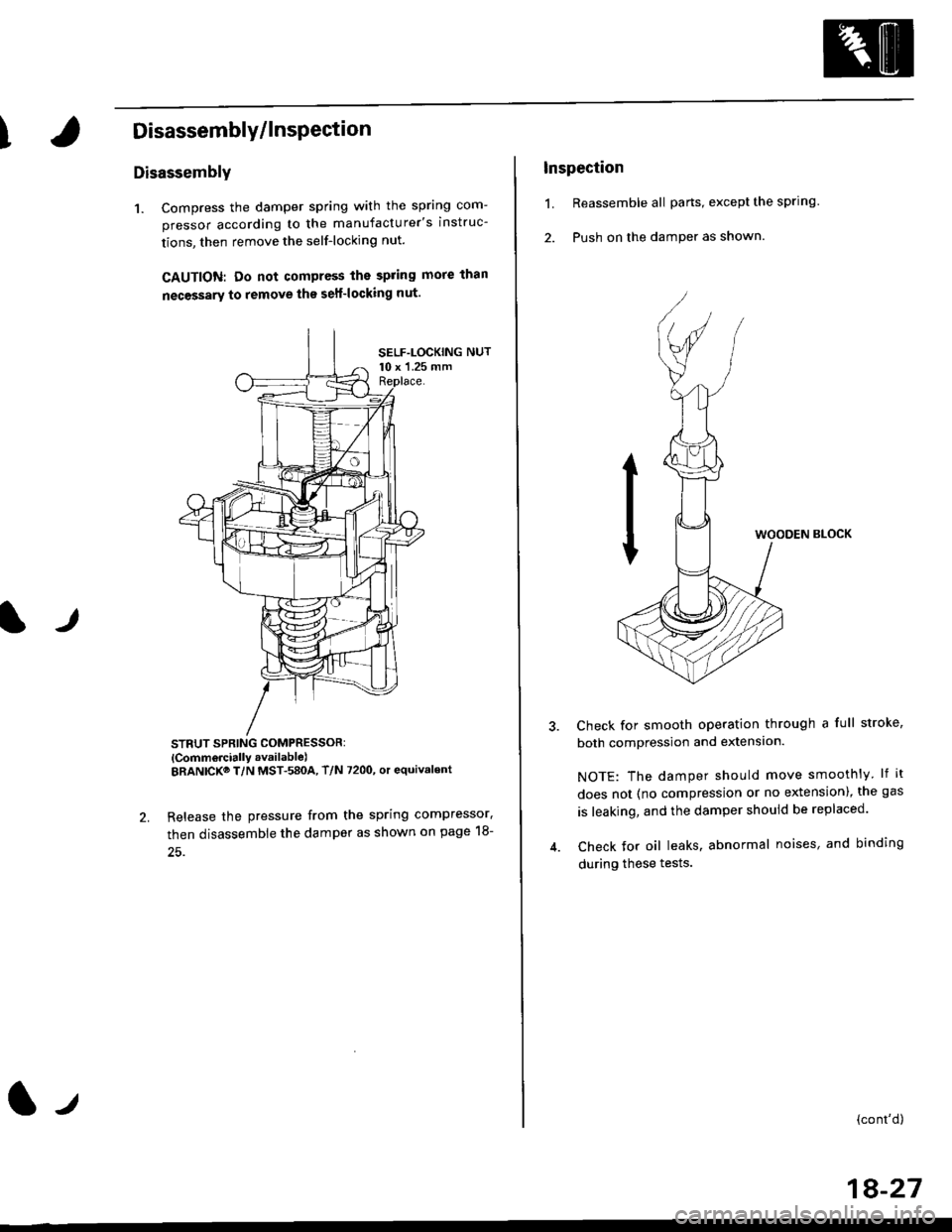
1. Compress the damper spring with the spring com-
pressor according to the manufacturer's instruc-
tions, then remove the self-locking nut.
GAUTION: Do not compress the spring more than
necessary to remove the sell-locking nut.
STNUT SPRING COMPRESSOR:
lComm6rcially .vailablelERANICKo T/N MST-580A, T/N 7200, or equivalent
Release the pressure from the spring compressor.
then disassemble the damper as shown on page 18-
(|-r
lnspection
1. Reassemble all parts, except the sprlng.
2. Push on the damPer as shown.
WOODEN BLOCK
Check for smooth operation through a full stroke,
both compression and extension.
NOTE: The damper should move smoothly lf it
does not (no compression or no extension), the gas
is leaking, and the damper should be replaced.
Check Jor oil leaks, abnormal noises, and binding
during these tests.
{cont'd)
18-27
Page 1246 of 2189
Doors
Door Panel Replacement
NOTE: Take care not to scratch the door panel andother pa rts.
'1. Remove:
. Inner handle trim (see page 20-14). Mirror mount cover panel (see page 20-24)
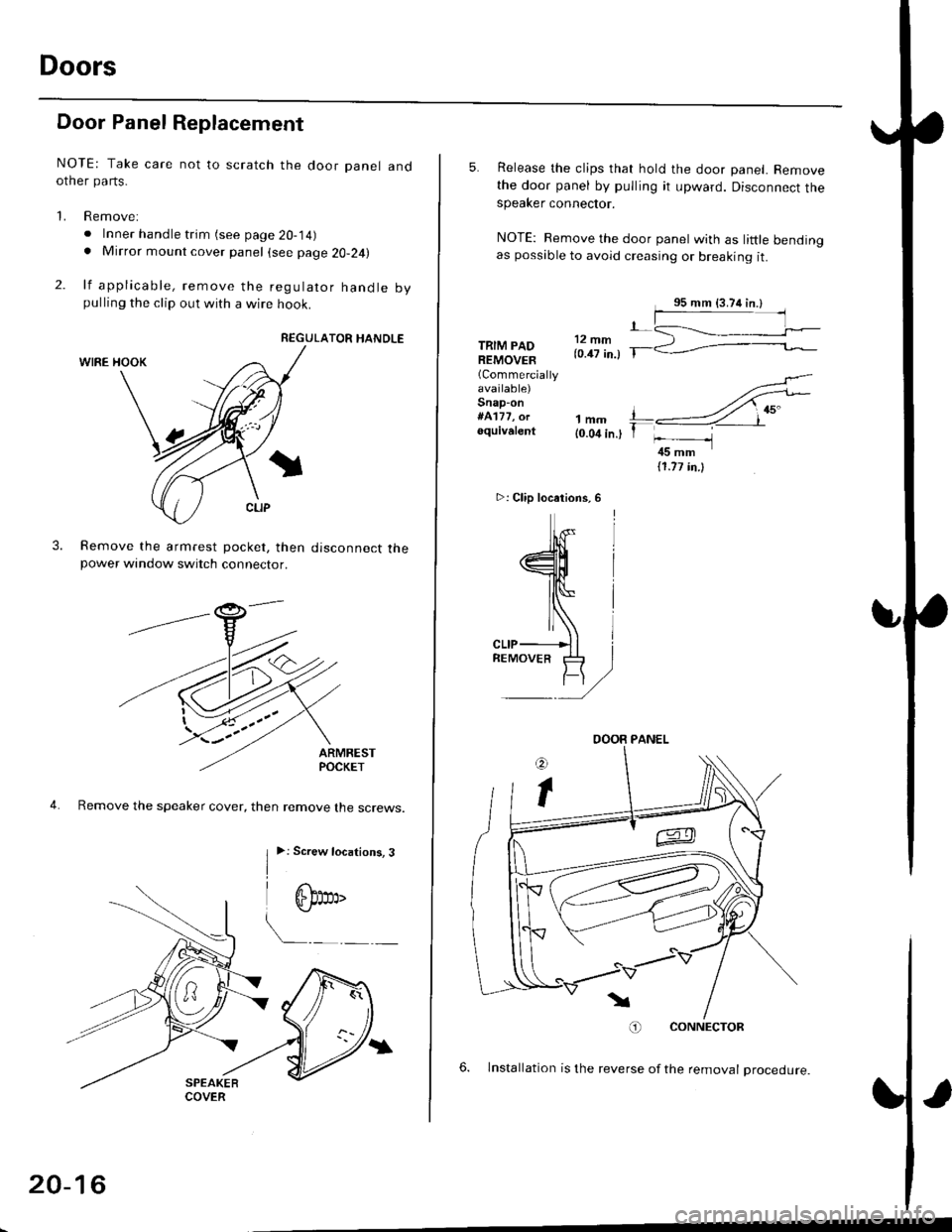
2. lf applicable, remove the regulator handle bypulling the clip out with a wire hook.
REGULATOR HANDLE
WIRE HOOK
Remove the armrest pocket, then disconnect thepower window switch connector.
ARMRESTPOCKET
4. Remove the speaker cover, then remove lhe screws.
3.
I
>: Screw locations, 3
| 6b:a,'
L"_
COVER
20-16
TRIM PADREMOVER(Commercially
available)Snap-on#A'177, orequivalent1mm{0.04 in.)
5. Release the clips that hold the door panel. Removethe door panel by pulling it upward. Disconnect thespeaker connector.
NOTE: Remove the door panel with as little bendingas possible to avoid creasing or breaking it.
.L12 fim(0.47 in.) T-
>: Clip locations,
l^
J[
=l$
ll,\*
atr-
,,)
REMoVER tl-)
11.77 in.l
O) CONNECTOR
6. lnstallation is the reverse of the removat oroceoure.
DOOR PANEL
Page 1429 of 2189
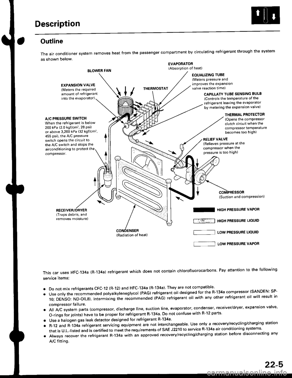
Description
Outline
The air conditioner system removes heat from the passenger compartment by circulating refrigerant through the system
as shown below.
BLOWER FAN
EVAPORATOR(Absorption of heati
EOUALIZING TUBE(Meters pressure andimproves the expansionvalve reaction time)
into the evaporator)CAPILLATY TUBE SENSING BULB
lControls the temPerature of the
ref rigerant leaving the evaporator
by metering the expansion valve)
/\
THERMOSTAT
A/C PRESSURE SWITCH
When the refrigerant is below
200 kPa (2.0 kgtcm',28 Psi)or above 3,200 kPa 132 kgflcm',
455 psi), the Ay'C pressure
switch opens the circuit to
the A,/C switch and stops the
EXPANSION VALVE(Meters the requiredamount of refrigerant
airconditioning to Protect the
compressor.
RECEIVER/DRYER(Traps debris, andremoves morsturel
THERMAL PROTECTOR
{Opens the comPressorclutch circuit when the
compressor temPeraturebecomes too high)
RELIEF VALVE(Relieves pressure at the
compressor when thepressure is too high)
(Radiation of heat)
I
f-r--; I
(Suction and comPression,
HIGH PRESSURE VAPOR
HtGH PRESSUBE LIOUID
LOW PRESSURE LIOUID
This car uses HFC-134a (R-134a) refrigerant which does not contain chlorofluorocarbons Pay attention to the following
service items:
. Do not mix refrigerants CFC-12 (R-12) and HFC-134a (R-134a)' They are not compatible'
. Useonlythe recommended polyalkyieneglycol (PAG) refrigerant oil designedforthe R-134a compressor (SANDEN: SP-
10; DENSO: ND_OIL8). Intermixing ihe re-commended (pAG) refrigerant oil with any other refrigerant oil will result in
compressor failure.
. All A,,ic system parts {compressor, discharge line, suction line, evaporator, condenser, receiver/dryer, expansion valve'
O-rings for joints) have to be proper for refrigerant R- 134a Do not confuse with R-l2 parts'
. Use a halogen gas leak detector designed for refrigerant R-134a
. R-12 and R-134a refrigerant servacing equipment are not interchangeable. Use only a recovery/recycling/charging station
that is u,L.-listed and is certified to meet the requirements of sAE J2210 to service R-134a air conditioning systems'
. Always recover the refrigerant R-134a with an approved recovery/recycling/charging station before disconnecting any
A,/C fitting.
S]
22-5
Page 1450 of 2189
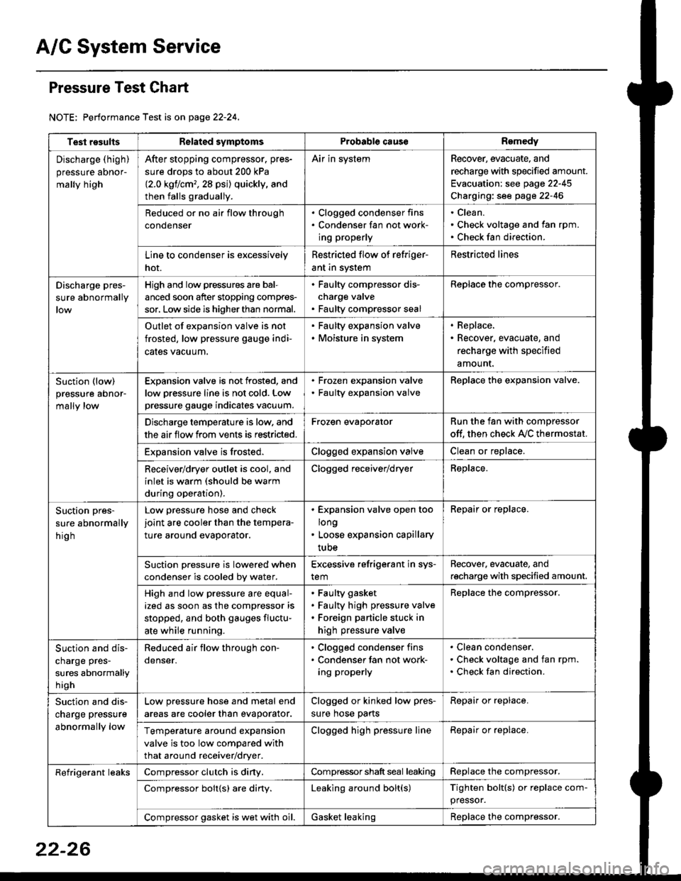
A/C System Service
Pressure Test Chart
NOTE: Performance Test is on page 22-24,
Test resultsRelated symptomsProbabl€ causeRemedy
Discharge (high)
pressure aDnor-
mally high
After stopping compressor. pres-
sure drops to about 200 kPa
{2.0 kgflcm,,28 psi) quickly, and
then falls gradually.
Air in systemRecover, evacuate, and
recharge with specified amount.
Evacuation: see page 22-45
Charging: see page 22-46
Reduced or no air flow through
condenser
. Clogged condenser fins. Condenser fan not work-
ing properly
Clean.
Check voltage and fan rpm.
Check fan direction.
Line to condenser is excessively
hot.
Restricted flow of refriger-
ant in system
Restricted lines
Discharge pres-
sure abnormally
High and low pressures are bal-
anced soon after stopping compres-
sor, Low side is higher than normal.
. Faulty compressor dis-
charge valve. Faulty compressor seal
Replace the compressor.
Outlet of expansion valve is not
frosted, low pressure gauge indi-
cales vacuum.
. Faulty expansion valve. Moisture in system
. Replace,. Recover, evacuate, and
recharge with specified
amount.
Suction (low)
pressure abnor-
mally low
Expansion valve is not frosted, and
low oressure line is not cold. Low
pressure gauge indicates vacuum.
. Frozen expansion valve. Faulty expansion valve
ReDlace the exoansion valve.
Discharge temperature is low. and
the air flow from vents is restricted.
Frozen evaporatorRun the fan with compressor
off. then check A,/C thermostat.
Exoansion valve is frosted.Clogged expansion valveClean or replace.
Receiver/dryer outlet is cool, and
inlet is warm (should be warm
during operation).
Clogged receiver/dryerReplace.
Suction pres-
sure abnormally
hig h
Low pressure hose and check
joint are cooler than the tempera-
ture around evaporator.
. Expansion valve open too
long. Loose expansion capillary
tube
Repair or replace.
Suction oressure is lowered when
condenser is cooled bv water.
Excessive refrigerant in sys-
tem
Recover. evacuate, and
recharge with specified amount.
High and low pressure are equal-
ized as soon as the compressor is
stopped, and both gauges fluctu-
ate while running.
Faulty gasket
Faulty high pressure valve
Foreign particle stuck in
high pressure valve
Replace the compressor.
Suction and dis-
charge pres-
sures abnormally
h igh
Reduced air flow through con-
denser.
. Clogged condenser fins. Condenser fan not work-
ing properly
Clean condenser.
Check voltage and fan rpm.
Check fan direction.
Suction and dis-
charge pressure
abnormally low
Low pressure hose and metal end
areas are cooler than evaporator.
Clogged or kinked low pres-
sure hose parts
Repair or replace.
Temperature around expansion
valve is too low compared with
that around receiver/dryer.
Clogged high pressure lineRepair or replace.
Refrigerant leaksCompressor clutch is diny,Compressor shaft seal leakingReplace the compressor.
Compressor bolt{s) are diny.Leaking around bolt(s)Tighten bolt(s) or replace com-
pressor.
Compressor gasket is wet with oil.Gasket leakingReplace the compressor.
22-26
Page 1561 of 2189
Battery
Test
@l. Battery lluid lelectrolytel contalns sulfuric acid. lt may cause severe burns it it gets on your skin ol in your eyes Wear
protective clothing and a face shield.
- It eleqtlolyte gets on your skin or clothes, rinse it off with watel immediately
- lf electrolyte gets in your eyes, flush it out by splashing water in your eyes for at least 15 minutes; call a physician
immediately.
. A battery gives off hydrogen gas. lf ignited, the hydrogen will explode and could crack the battery case and splatter
acid on you. Keep sparks, flames, and Gigarettes away from the battery'
o Overchaiging will raise the temperature oI the electrolyte. This may force electrolyte to spray out ot ths battery vents'
Follow the charger manufacturel's instrustions, and chalge the battery at a propcr rate.
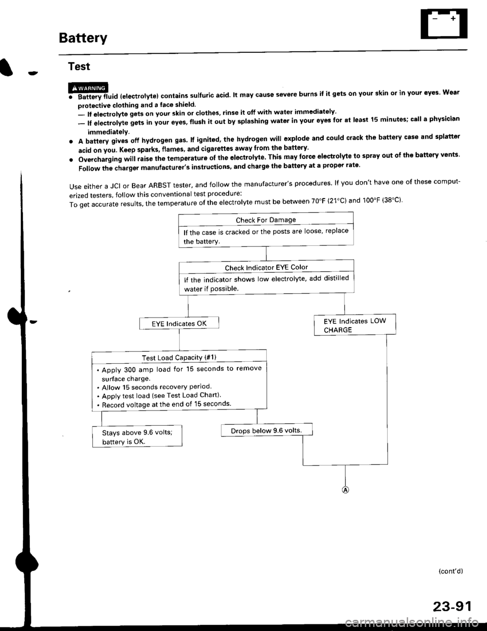
Use either a JCI or Bear ARBST tester. and follow the manufacturer's procedures. lf you don't have one of these comput-
erized testers, follow this conventional test procedure:
ToqetaccurateresuIts,thetemperatureoftheeIectro|ytemustbebetweenT0"F(21.c)and100"F(38.c}'
lf the case is cracked or the posts are loose, replace
the battery.
lf rhe indicator shows low electrolyte, add distilled
water if Possible.
EYE lndicates OK
Test Load CaPacitY (#l )
. Apply 300 amp load for 15 seconds to remove
surface charge.. Allow 15 seconds recovery Perloo.. Apply test load {see Test Load Chan).
. Record voltage at the end of l5 seconds.
Drops below 9.6 volts.Stays above 9.6 volts;
battery is OK.
(cont'd)
23-91
Page 1641 of 2189
Taillights
Replacement (Except'99 - 00 Sedanl
NOTE:
. Inspect the gasket; replace it il it is distorted or stays
compressed.
. After installing the taillights, run water over them to
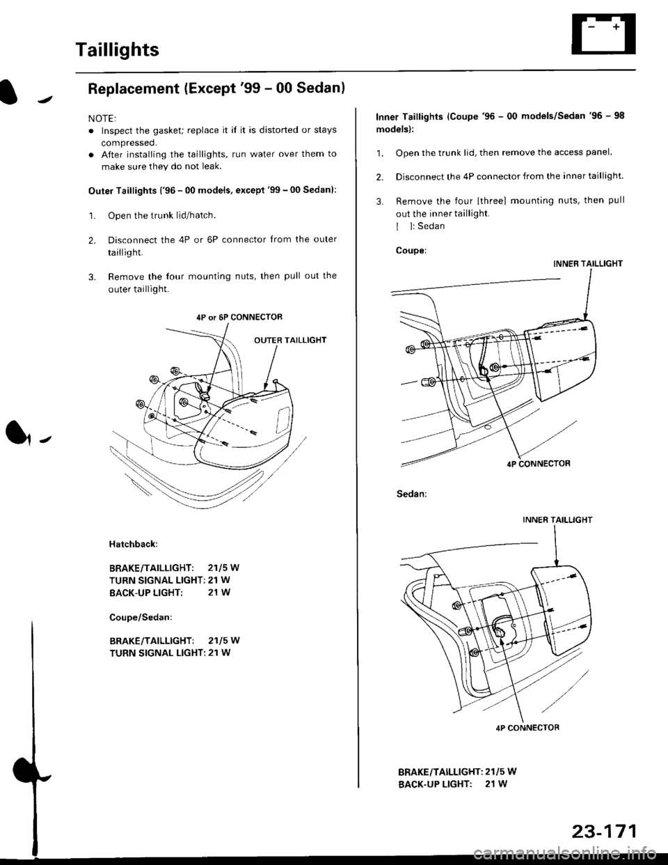
make sure they do not leak.
Outer Taillights ('96 - 00 models, except'99 - 00 Sedan):
1. Open the trunk lid/hatch.
2. Disconnect the 4P or 6P connector trom the outer
taillight.
3. Remove the four mounting nuts, then pull out the
outer taillight.
l-
Hatchback:
BRAKE/TAILLIGHT: 2115W
TURN SIGNAL LIGHT: 21 W
BACK-UP LIGHT: 21 W
4P or 6P CONNECTOR
BRAKE/TAILLIGHT: 2115W
TURN SIGNAL LIGHT: 21 W
BRAKEiTAILLIGHT: 2115 W
BACK-UP LIGHT: 21 W
Inner Taillights (Coupe'96 - 00 models/Sedan'96 - 98
models):
1. Open the trunk lid, then remove the access panel.
2. Disconnect the 4P connector from the inner taillight.
3. Remove the four [three] mounting nuts, then pull
out the inner taillight.
I l: Sedan
Coupei
INNER TAILLIGHT
Sedan:
INNER TAILLIGHT
4P CONNECTOB
Page 1642 of 2189
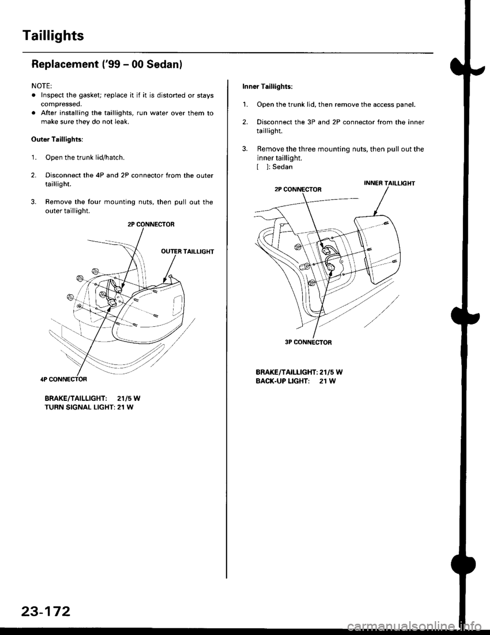
Taillights
Replacement ('99 - 00 Sedanl
NOTE:
. Inspect the gasket; replace it if it is distorted or stays
compressed.
. After installing the taillights, run water over them to
make sure they do not leak.
Outer Taillights:
1. Open the trunk lid/hatch.
2. Disconnect the 4P and 2P connector trom the outer
taillight.
3. Remove the four mounting nuts, then pull out the
outer taillight.
TAILLIG}fi
4P CONNECTOR
BRAKE/TAILLIGHT: 2115W
TURN SIGNAL LIGHT: 21 W
r*i/et./
23-172
Inner Taillights:
'1. Open the trunk lid, then remove the access panel.
2. Disconnect the 3P and 2P connector from the inner
taillight.
3. Remove the three mounting nuts, then pull out the
inner taillight.
[ ]: Sedan
BRAKE/TAILLIGHT: 2r15 W
BACK.UP LIGHT: 21 W
3P CONNECTOR
Page 1782 of 2189
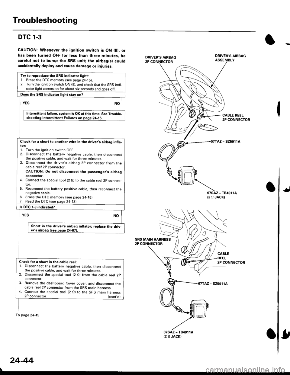
Troubleshooting
DTC 1-3
CAUTION: Whenever the ignition switch is ON {lll, orhas been turned OFF lor less than thrEe minutes, becaroful not to bump the SRS unit; the airbag(s) couldaccidenlally deploy and cause damage 01 iniuries.
DRIVER'S AIRBAGASSEMALY
REEL2P CONNECTOR
AZ - SZ5011A
07saz - TB4011A{2 0 JACK)
CABLEREEL2P CONNECTOR
07TAZ - SZ5011A
TrV to reproduce the SRS indicator light:1. Erase the DTC memory (see page 24-15).2. Turn the ignition switch ON (ll), and check that the SRS indicator light comes on for about six seconds and goes off.
Does the SRS indicalor light stav on?
YESNO
Intermittent lailure. system is OK ai this tim€. Se€ Troubl€-shooting Intermittent Failures on page 24-15.
Check tor a short lo another wire in the drivo.'s eirbrg in{la-
1. Turn the ignition switch OFF.2. Disconnect the battery negative cable, then disconnectthe positive cable, and wait for three minutes.3. Disconnect the driver's airbag 2P connector from thecable reel 2P connector,CAUTION: Do not disconnect the passenger's airb.gconnector,4. Connect the special tool (2 0)to the cable reel 2P connector,5. Reconnect the baftery positive cable, then reconnect thenegative cable,6. Erase the DTC memory (see page 24 15).7. Read the DTC (see page 24-13).
ls DTC 1-3 indicated?
NOYES
Shon in the driver's airbag intlator; replace the driv-er's airbag {see page 24-67}.
Check lor a short in the ceble reel:1. Disconnect the battery negative cable, then disconnectthe positive cable, and wait for three minutes.2. Disconnect the special tool (2 O) from the cable reel 2p
3. Remove the dashboard lower cover, and disconnect thecable reel 2P connector from the SRS marn naroess.4. Connect the special tool (2 O) to the SRS main harness2P coonector. {cont,di
fo page24-45
SRS MAIN HARNESS
24-44
07sAz - TBr011At2 0 JACKI