Gas HONDA CIVIC 1996 6.G Workshop Manual
[x] Cancel search | Manufacturer: HONDA, Model Year: 1996, Model line: CIVIC, Model: HONDA CIVIC 1996 6.GPages: 2189, PDF Size: 69.39 MB
Page 1786 of 2189
Troubleshooting
DTC 1-5
CAUTION: Whenever the ignition switch is ON {ll). or
has been turned OFF for less than three minutes, be
caretul not to bump ths SRS unit; the airbag(sl could
accidentally deploy and cause damage or iniuries.
J
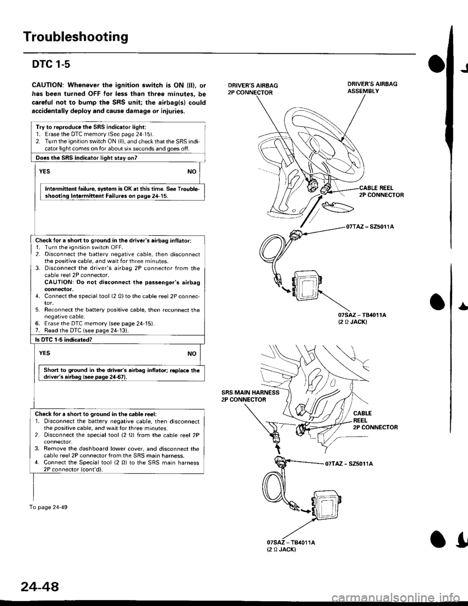
DRIVER'S AIRBAG2P CONNECTOR
SRS MAIN HARNESS2P CONNECTOR
DRIVER'S AIRBAGASSEMBLY
REEL
07sAz - TB40't1A(2 0 JACK)
2P CONNECTOR
AZ - SZ5011A
CABLEREEL2P CONNECTOR
I
07TAZ - SZ5011A
Try to rep.oduce the SRS indicator light:1. Erasethe DTC memorv (See page 24'15).2. Turn the ignition switch ON (ll), and check that the SRS indicator light comes on tor about six seconds and goes off.
Ooes the SRS indicator light stay onl
YESNO
Intermittent lailure, system is OK at this time. See Trouble-shooting lntormittent Failure3 on page 24-15.
Check for a short to ground in lh€ driver's airbag inllator:1. Turn the ignition switch OFF.2. Disconnect the battery negative cable, then disconnectthe positive cable, and wait for three rninutes.3. Disconnect the driver's airbag 2P connector from thecable reel 2P connector.CAUTION: Do not disconnect tho p.ssenger's airbagconnectoa.4. Connect the specialtool (2 0)to the cable reel 2P connector.5. Reconnect the batlery positive cable, then reconnect thenegative cable-6. Erase the DTC memory (see page 24-15).7. Read the DTC (see page 24-131.
ls OTC 1-5 indicatedT
YESNO
Short to ground in the drive/s airbeg inflator; r€pl.ce thedriver's.iib.g (see page 24d1.
Check lor a short to ground in the csble reer:l. Disconnect the battery negative cable, then disconnectthe positive cable, and wait for three minutes.2. Disconnect the special tool {2 (}) from the cable reel 2P
3. Remove the dashboard lower cover, and disconnect thecable reel 2P connector from the SRS main harness.4. Connect the Special tool {2 0} to the SRS main harness2P connector (cont'd).
To page 24-49
{2 0 JACK)
24-44
.I
Page 1901 of 2189
I -.. t
iecnuaruerirt Rererence rp iiftii* l"*o, $'n"o.
t
.i sensor Input voltaqe sensor input inpul input inp"r II TEGFL' rvca?r Opsl rFirir.rxt rECn i,ari tL------- _______.J
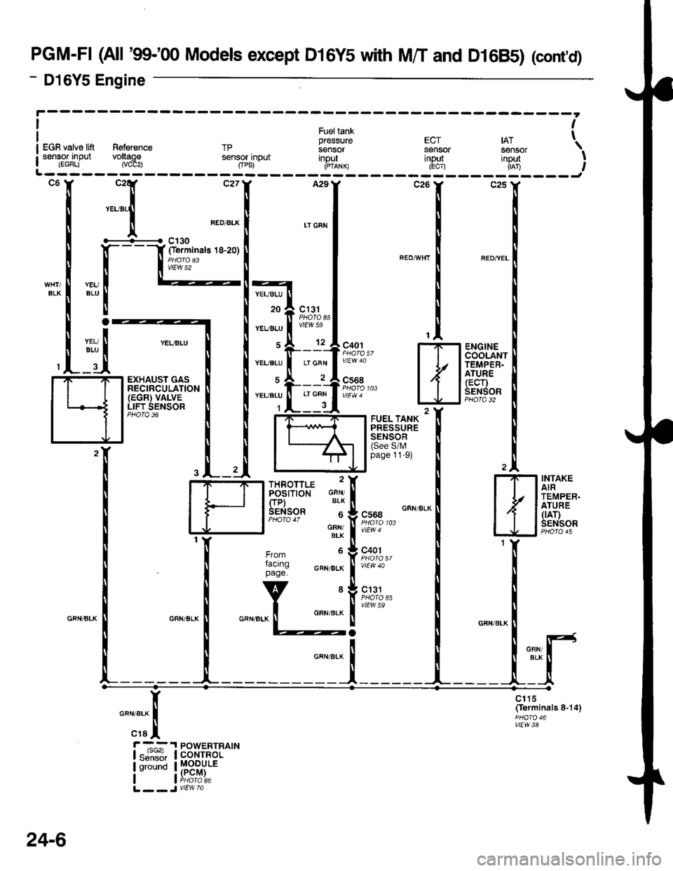
PGM-FI (All '99-'00 Models except D16Y5 with M/T and D16B5) (cont,d)
- D16Y5 Engine
BLK
c131PHOTOssvtEW 59
ENGINECOOLANTTEMPER.ATURE(ECr)SENSORPBO|A 32
c130Oerminals 18-20)
vtEW 52
YEUALU
20
YEUALU
YEUALU
YEUBLU
1
YEUBLU
ALU
LT GFN
EXHAUST GASRECIRCULATION(EGR) VALVELIFT SENSORPHO|O 36
TEMPER.
tllfrtr'l
I J tffiT,.:'
""",:I
1r:{
Slt or
lr;: H
H#*iiff''I
fi[ffi,''""."'.1
"_
[;,l;,+. N
:{I
c1t5(ferminals 8-14)
vtEw38
n"","*[
"raI
r -,^^:.I POWERTRAIN| "ji""il, I corrnor
lu'"t !H"3fii:'L __ J V|EW 7a
24-6
Page 1913 of 2189
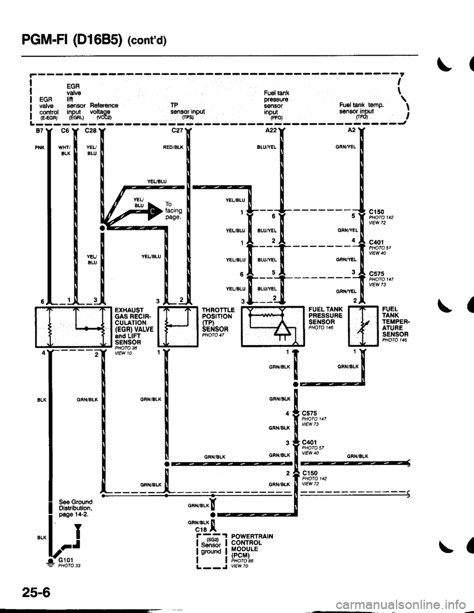
PGM-FI (D1685) (cont'd)
EGRvdvo Fuer ia ( tEGR In pres$uro \valvs s€mor nd*6nc6 lP i.snsor h.tsl lank tenF, Icont ol inDut volt|ce s8fi8of inDul inbut ssnsof ifix, I: control inDln voltac€ s€{tlor input inout sonsol ingJl ;I G.€GF} GGf,q N@a fiPg' .(PFoJ fiFO) ,L------- ------J
j
c2887
c150PHOTO 112
C'ro1PHO|O sl
c575
vtEw 7i
(FUELTA}IKTEMPEB.ATURESENSOR
H1Y
FUEL TANKPRESSURESENSOnPHOTO 116
THROTTLEPOSrT|0NCIP)SENSOR
EXHAUSTGAS RECIR.CULATION(EGR) VALVEand LIFTSENSORPHOfO 36
"""r":x
o
GRI{/BLK
4
GNN/BLK
GNN/gLK
c575
c401PHOfO 57vtEw 40
2
GRN/BL(
cls0
a
POWERTBAINCONTROLMOOULE(PCM)PHOfO 86
I
I
IJ
n"*r"a^[
'rcai/BLX llcre Ar--?
lsJiH,
I ground
I
25-6
Page 1980 of 2189
Gauges (cont'd)
- How the Gircuit Works
When the ignition switch is in ON (ll) or START (lll),
battery voltage is supplied through fuse 25 to the
gauges in the gauge assembly.
Speedometer and Odometer
The odometer and soeedometer drive circuits
receive pulses from the vehicle speed sensor
(VSS). The pulse rate increases as the car
accelerates. The frequency and duration of these
input pulses are measured and displayed by the
speedometer, odometer and tripmeter.
Tachometer
The tachometer drive circuit receives pulses from
the ignition control module (lCM) in the distributor
assembly or the ECM/PCM. The solid-state
lachometer then displays these pulses as engine
speed. For each 200 pulses per minute from the
ignition control modul€ (lCM) or the ECM/PCM, the
tachometer displays 100 RPM.
Engine Coolant Temperature Gauge
The engine coolant temperature gauge has two
intersecting coils wound around a permanent
magnet rotor. Voltage applied to the coils, through
fuse 25, generates a magnetic lield. The magnetic
field, controlled by the coolant temperature sending
unit, causes the rotor to rotate and the gauge
needle to move. As the resistance in the sending
unit varies, current through the gauge coils
changes. The gauge needle moves toward the coil
with the strongest magnetic field.
The 6ngine coolant temperature sending unit's
resistance varies from about 137 ohms at low
engine temperature to between 3H6 ohms at high
temperature (radiator fan running).
Refer to the Service Manual (Section 23, Electrical)
for specific tests or troubleshooting procedures.
81-2
(
Fuel Gauge (All except cX)
The fuel gauge has two intersecting coils wound
around a permanent magnet rotor. Voltage applied
to the coils, through tuse 25, generates a magnetic
field. The magnetic field, controlled by the fuel
gauge sending unit, causes the rotor to rotate and
the gauge needle to move. As the resislance in the
sending unit varies, current through the gauge coils
changes. The gauge needle moves toward the coil
with the strongest magnetic field.
The fuel gauge sending unit's resistance varies
from about 2-5 ohms at full, to about 110 ohms at
empty. When you turn the ignition switch off, the
gauge remains at the last reading until you turn the
ignition switch to ON (ll) or START (lll) again,
Refer to the Service Manual (Section 23, Electrical)
for specific tests or troubleshooting procedures.
Fuel Gauge (GX)
The fuel gauge has two intersecting coils wound
around a permanent magnet rotor. Voltage applied
to the coils, through fuse 25, generates a magnetic
field. The magnetic field, controlled by the PCM,
causes the rotor to rotate and the gauge needle to
move. The PCM calculates the gas quantity in the
fuel tank by using the fuel pressure value detected
by the tuel tank pressure sensor and the fuel
temperature value detected by the fuel tank
temperalure sensor, and outputs the signal to the
gauge assembly. The gauge needle moves toward
the coil with the strongest magnetic field.
When you turn the ignition switch off , the gauge
remains at the last reading until you turn the ignition
switch to ON (ll) or START (lll) again. When the
PCM detects a malfunction with the fuel pressure or
temperature, or detects a gas leak, the PCM
reduces the fuel meter to 0.
Refer to the Service Manual GX Supplement
(Section 11 , Fuel and Emissions) for specific tests
or troubleshooting procedures.
a
a
Page 2108 of 2189
-
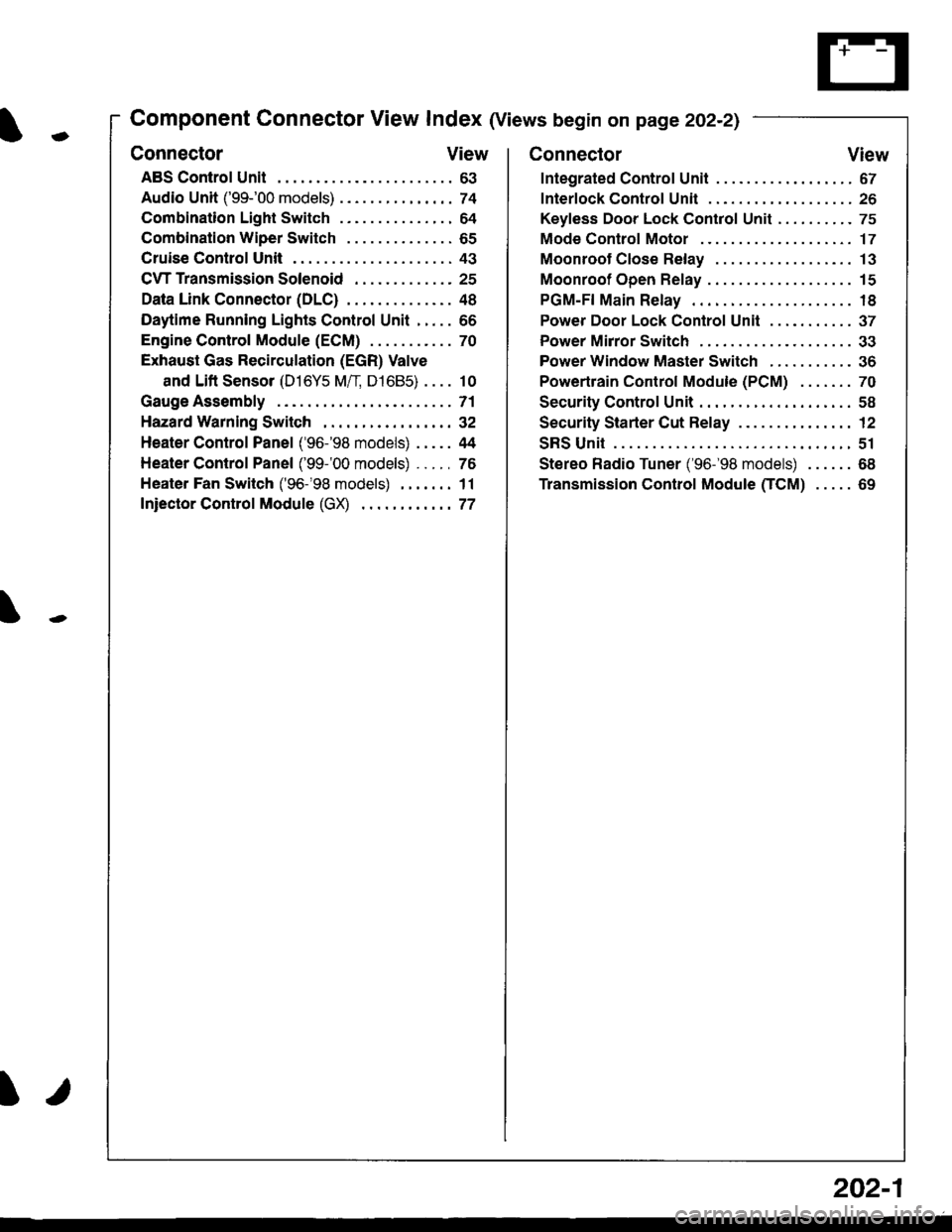
Component Connector View Index (Views begin on page 202-21
Connector View
ABS Control Unit........ ......63
Audio Unit ('99-'00 models) ......74
Combination Light Switch . . . . . . . . . . . . . . . 64
Combination Wiper Switch . . . . . . . . . . . . . . 65
Cruise Control Unit.... .....43
C\TTTransmission Solenoid ............. 25
Data Link Connector (DLC) ..... 48
Daytime Runnlng Lights Control Unit ..... 66
Engine control Module (ECM) ...........70
Exhaust Gas Recirculation (EGR) Valve
and Lift Sensor (D16Y5 Mfl, D1685) . . . . 10
Gauge Assembly .............71
HazardWarnlngSwitch,,. .,,,...,,,,... 32
Heater Control Panel ('96-'98 models) .....44
Heater Control Panel ('99-'00 models) ...., 76
Heater Fan Switch ('96-'98 models) ,,,.... 11
fniector Control Module (GX) ............77
I/
202-1
Connector View
Integrated Control Unit .......,. 67
f nterfock Control Unit .... ...... 26
Keyfess Door Lock Control Unit . . . . , . . . . . 75
Mode Control Motor ... ........'17
Moonroof Close Relay .. .......13
Moonroof Open Relay ... .......15
PGM-FI Main Relay .. .......... 18
Power Door Lock Conlrol Unil ..... ...... 37
Power Mirror Switch .,... ...... 33
Power Window Master Switch .,.........36
Powertrain Control Module (PCM) .......70
Security Control Unit ..., ..,,... 58
Security Starter Cut Belay ... ...,,,....,, 12
SRS Unit ............. 51
Stereo Radio Tuner ('96-'98 models) ...... 68
Transmission Control Module CICM) .....69
Page 2110 of 2189
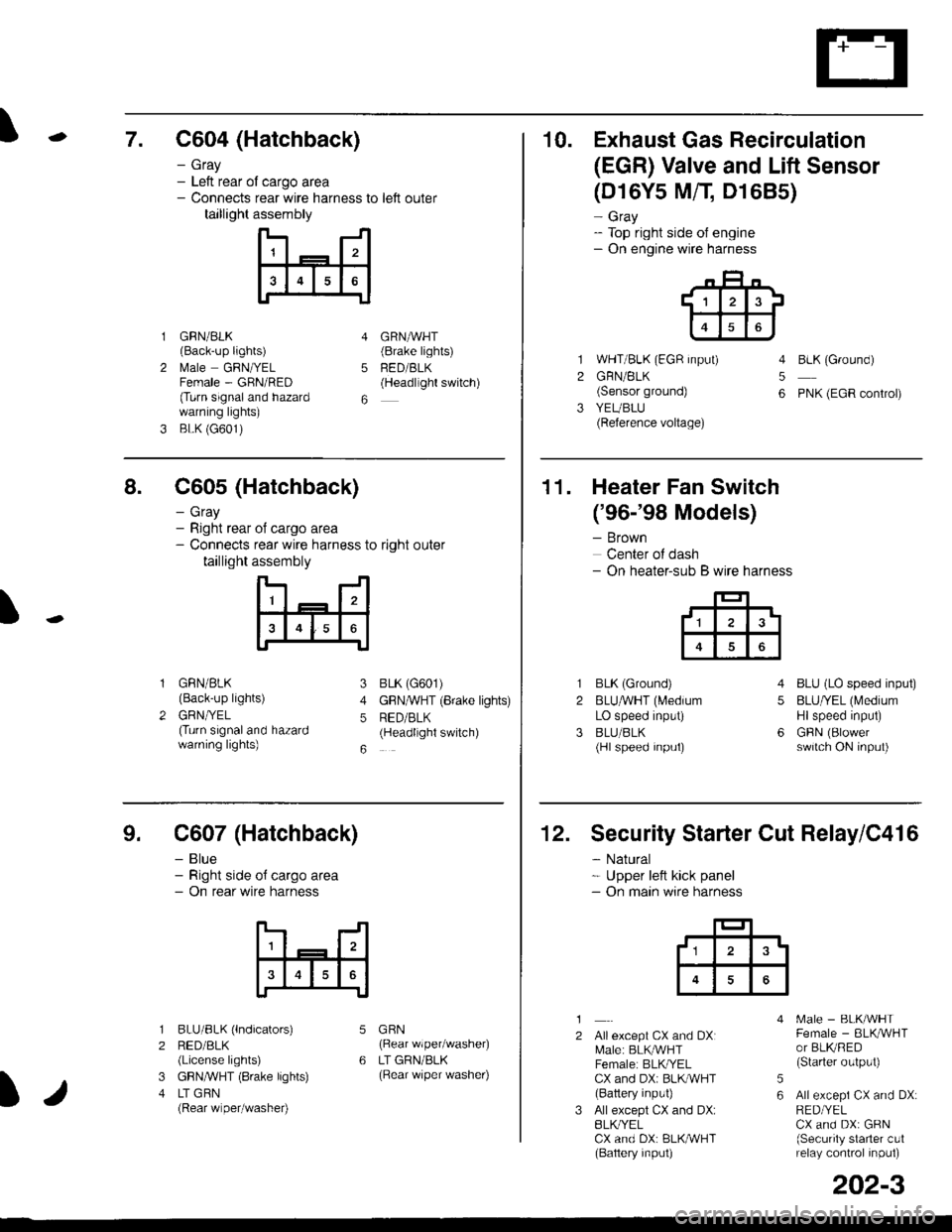
\7. C604 (Hatchback)
GRN/BLK(Back-up lights)
l\4ale GRNIYELFemale - GRN/RED(Turn signaland hazardwarning lights)
BLK (G601)
- Gray- Left rear ol cargo area- Connects rear wire harness to left outer
taillight assembly
4
5
6
1
2
GRNAVHT(Brake lights)
FED/BLK(Headllght switch)
10. Exhaust Gas Recirculation
(EGR) Valve and Lift Sensor
1
2
3
(D16Y5 MfI D1685)
- Gray- Top right side of engine- On engine wire harness
WHT/BLK (EGR input)
GRN/BLK(Sensor ground)
YEUBLU(Reference voltage)
4
5
6
BLK (Ground)
PNK (EGR control)
of cargo area
rear wire harness to right outer
assembly
n- -n
a t | _ a2a
l3I4t5tttl
IJ
I
8. C605 (Hatchback)
- Gray- Right rear- Connects
taillight
GRN/BLK(Back-up lights)
GRNTYEL(Turn signaland hazardwarning lights)
3
4
5
6
1
2
BLK (G601)
GFNAVHT (Brake lights)
RED/BLK(Headlight switch)
11. Heater Fan Switch
('96-'98 Models)
- Brown
Center of dash- On heater-sub B wire harness
BLK (Ground)
BLUAVHT (L4edium
LO speed input)
BLU/BLK(Hl speed input)
4
5
6
1
2
3
BLU (LO speed input)
BLU/YEL (Medium
Hlspeed input)
GFIN (Blowerswitch ON input)
9. C607 (Hatchback)
- Blue- Right side o{ cargo area- On rear wire harness
BLU/BLK (lndicators)
RED/BLK(License lights)
GBN,ryVHT (8rake lights)
LT GBN(Rear wiper/washe0
5
6
1
2
3
4
GRN(Rear wiper/washer)
LT GRN/BLK(Rear \/iper washer)
)/
202-3
12. Security Starter Cut Relay/C416
- Natural* Upper left kick panel- On main wire harness
1
2Allexcept CX and DXI[,4ale: BLK,^r'r'HTFemale: BLKI/ELCX and DXi BLI(WHT(Battery input)
All except CX and DX:BLK^/ELCX and DX: BLK/WHT(Baftery input)
[.4ale - BLK/WHTFemale - BLKAVHTor BLKRED(Starter output)
All excepi CX and DX:RED/YELCX and DX: GRN(Security starter c!1relay control inpul)
5
6
tl3'