PCM HONDA CIVIC 1996 6.G Workshop Manual
[x] Cancel search | Manufacturer: HONDA, Model Year: 1996, Model line: CIVIC, Model: HONDA CIVIC 1996 6.GPages: 2189, PDF Size: 69.39 MB
Page 508 of 2189
JI
I
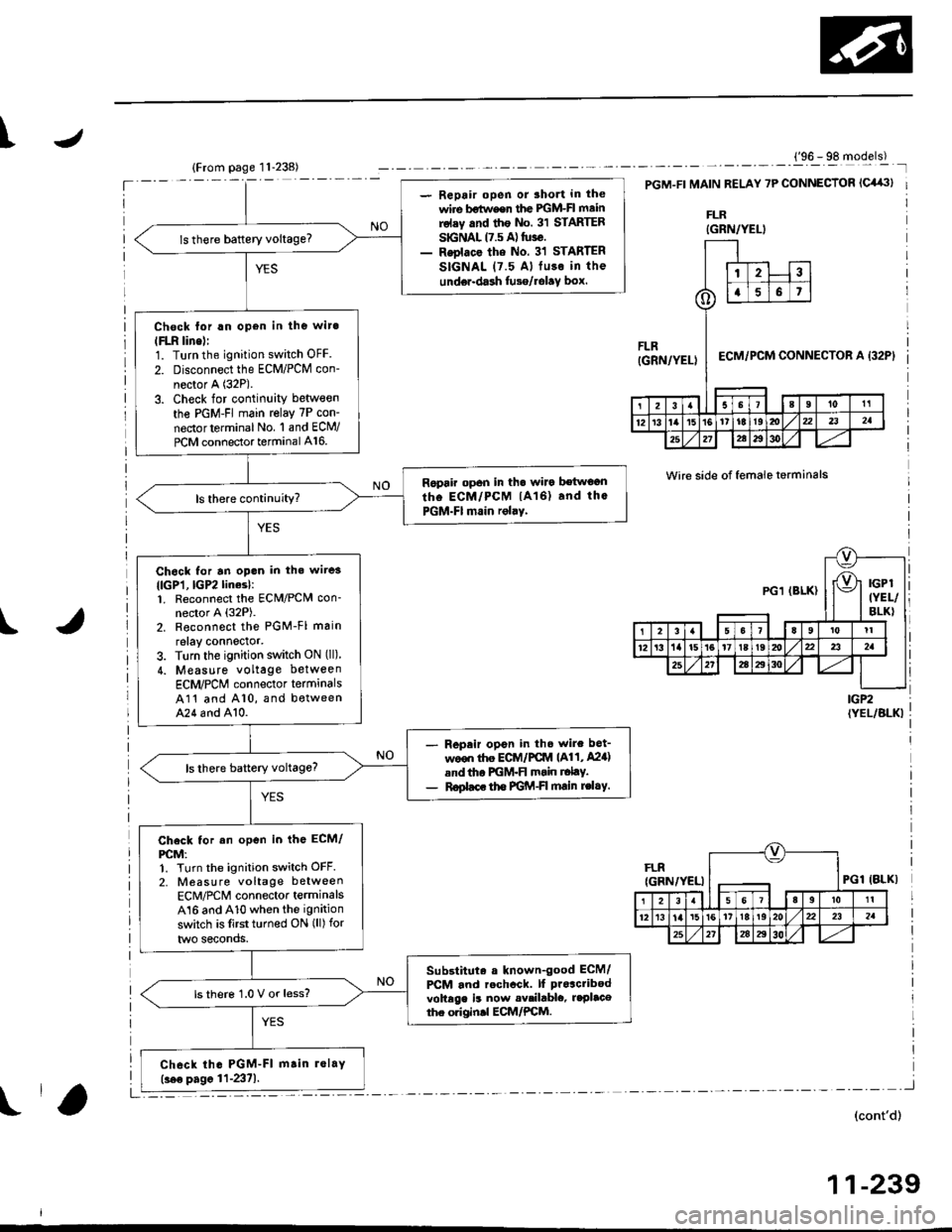
- Repair open or 3hort in the
wire bstw€er the lGM-Fl mainrolsy .nd the No. 31 STARTERSGNAL 17.5 A) tuse.- Reolace the No. 31 STARTER
SIGNAL (7.5 Al fu3o in the
unde.-dash tusg/rolav box.
ls there baftery voltage?
Chock lor !n open in the wit.
lFLn line)l1. Turn the ignition switch OFF
2. Disconnect the ECM/PCM con-
nector A (32P).
3. Check for continuity between
the PGM-FI main relay 7P con-
nectorterminal No. 1 and ECM/
PCM connector terminal A16.
Ropair op6n in th. walo betwoanthe ECM/PCM lA16) and thc
PGM-FI main rolaY.
Ch6ck for an opon in th. wi.e3
llcPl,lGP2linesl:1. Reconnect the ECM/PCN4 con-nector A (32P).
2. Reconnoct the PGM-Fl main
relay connector,3. Turn the ignition switch ON (ll)
4. Measure voltage between
ECM/PCM connector termanals
A11 and A10, and betweenA24 6nd A10.
Repeir opon in th6 wire bet-
ween ttre ECiA /PCM (A11, A24)
and tho PGM-FI msin r.lty.
R€plac. tho FGM-FI main rc|.Y.
Check tor an open in the ECM/
PCM:1. Turn the ignition switch OFF.
2, Measure voltage between
ECM/PCM connector terminalsA16 and A10 when the ignition
switch is lirst turned ON (ll) for
two seconds.
Substituta a known-good ECM/
PCM and rechcck. lf proacribod
voltege is now availablc, r.Placethe originll ECM/PCM.
ls thero 1.0 V or less?
Ch6ck th. PGM-FI m.in lolay(.ee pagc 11-2371.
('96 - 98 models)
t32Pt
Wire side of female terminals
IGP2{YEL/BLKI
FLRIGRN/YELIPGl
3l5 6 7l lslel tl1l
1213'tal5t6't7t8t920221 232a
2527284t
(cont'd)
1 1-239
IBLK)
{GRN/YELI
FLR(GRN/YELI
23
()a6t
ECM/PCM CONNECTOR A
21Il0t1
12r31'al5't61'tti9ml,/x2232a
25212e293ol./
PGl (BLK)
1I
12't/t15t617t8t9zi
25272A4t304l
Page 509 of 2189
Fuel Supply System
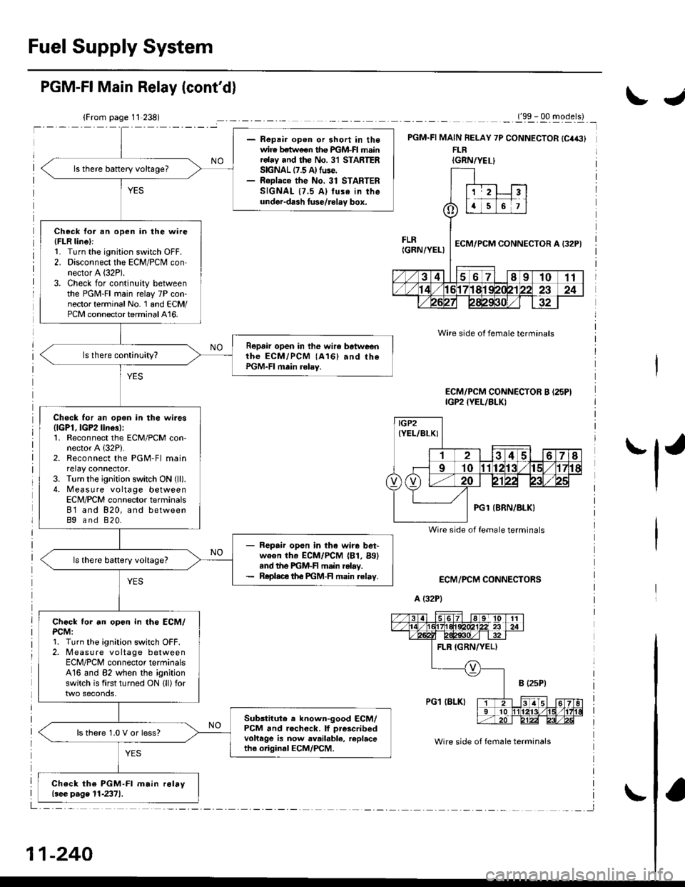
- Repair op€n or short in thewir€ betlveen the PGM-FI mainrelay and the No. 31 STARTERSIGNAL 17.5 A) fuse.- RoDlace the No. 31 STARTERSIGNAL {7,5 Al tuse in theunder-dash luse/rolay box.
ls there battery voltage?
Check tor an open in the wire(FLR linel:1. Turn the ignition switch OFF.2. Disconnect the ECM/PCM con-nector A (32P).
3. Check for continuity betweenthe PGM-FI main relay 7P con-nector terminal No. 1 and ECM/PCM connector terminal A16.
Repair open in the wir6 botweenthe ECM/PCM (A161 and rhePGM-FI main relay.
Check for an open in the wires{lGPl, lGP2 line3):1. Reconnect the ECM/PCM con-nector A {32P).2. Reconnect the PGM-Fl mainrelay connector.3. Turn the ignition switch ON (ll).
4. Measure voltage betweenECN4/PCM connector terminals81 and 820, and betweenBg and 820.
- Repair open in the wire bet-ween th. ECM/PCM (81, Bg)snd the PGM-F main rolay.- Roplace th€ PGM-FI main relav.
Chock tor an open in th6 ECM/PCM:1. Turn the ignition switch OFF.2. Measure vo ltage betweenECM/PCM connector terminalsA16 and 82 when the ignitionswitch is first turned ON lll) for
Sub3titute . known-good ECM/PCM and rochock. lf prescribedvohege is now available, replacethe original ECM/PCM.
ls there 1.0 V or less?
Chock the PGM-Fl m.in r6lay{see p.ge 11-2371.
PGM-FI Main Relay (cont'd)
_._(9x . qq -gqerll _
PGM.FI MAIN FELAY 7P CONNECTOR {C4€}FLR
ECM/PCM CONNECTORS
A (32P1
Wire side ot female terminals
Wire side of fem6le terminals
ECM/PCM CONNECTOR B {25PIIGP2 {YEL/BLKI
IGRN/YEL}
IGP2(YEL/BLKI
Wire side of female terminals
11-240
IJ
'l'
Page 522 of 2189
\
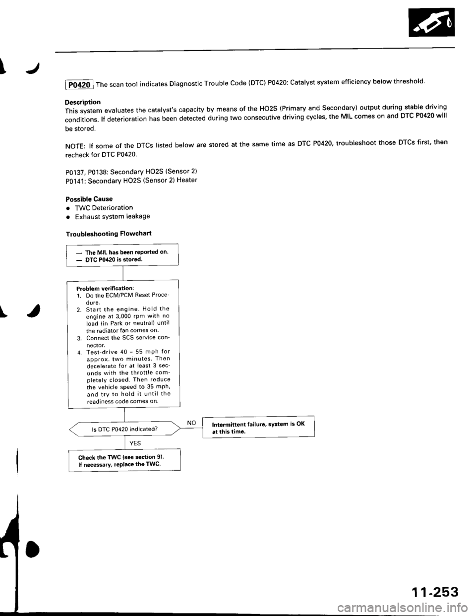
lTo420l Th" """n toot indicates Diagnostic Troubte code (DTc) p0420: catatyst sysrem efficiency below threshold.
Description
This system evaluates the catalyst's capacity by means of the Ho2s {Primary and secondary) output during stable driving
conditions. ll deterioration has been detected during two consecutive driving cycles. the MIL comes on and DTC P0420 will
be stored.
NOTE: lf some of the DTCS tisted below are stored at the same time as DTC P0420, troubleshoot those DTCS first. then
recheck for DTC P0420
P0137, P0138: Secondary HO2S (Sensor 2)
Po14'1:Secondary H02S {Sensor 2) Heater
Possibl€ Cause
. TWC Deterioration
. Exhaust system leakage
Troubleshooting Flowchart
I
The MIL has been reported on.
DTC P0420 is stored
Problem verilication:1. Do the ECM/PCM Reset Proce
dure.2. Start the engine Hold the
engine at 3,000 rpm wath no
load {in Park or neutral) until
the radiator fan comes on.
3. Connect the SCS service con
4. Test drive 40 - 55 mph for
approx, two minutes Then
decelerate for at least 3 sec_
onds with the throttle com'pletely closed- Then reduce
the vehicle speed to 35 mph,
and try to hold it until the
readiness code comes on
Intermittent Iailure, system is OK
at this time.ls DTC P0420 indicated?
Check the TWC {see section 9l
lf necessary, replace the TwC
Page 524 of 2189
4
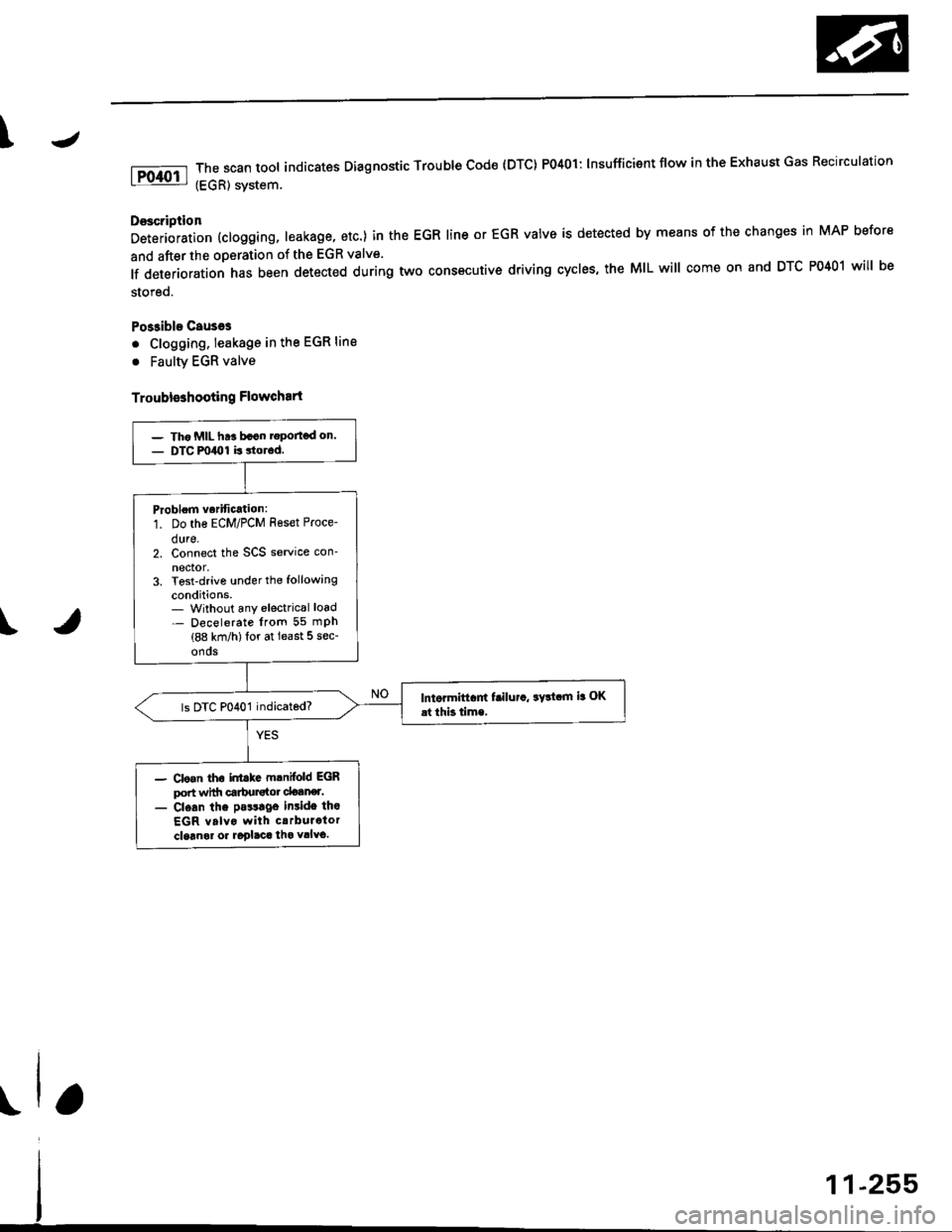
The scan tool indicates Dlagnostic Trouble cod€ {DTc} Po4ol: lnsufficient flow in the Exhaust Gas Recirculation
(EGR) svstem.
Doscription
Deterioration (clogging, leakage, etc.) in the EGR line or EGR valve is detected by means of the changes in MAP before
and after the operation of the EGR valve.
lf deterioration has been detected during two cons€cutive driving cycles, the MIL will come on and DTC P0401 will be
stored.
Po$ible Causeg
. Clogging. leakage in the EGR line
. Faulty EGR valve
Troubleshooting Flowchart
\
- Tho MIL ht! bacn rgportod on.- DTC m40l is 3torod.
Problom vorification:
1. Do the ECM/PCM Reset Proce-
dure.2. Connect the SCS service con-
nector,3. Tost-drive under the following
conditions.- Without any electrical load- Decelerate lrom 55 mPh(88 km/h)lor at least 5 sec-
onos
lntormiftam f!ilu.a, ayltam ia OK
.t thb time,
- Clo.n tho inttkc mlnifold EGRport wittr carbursto. clotner.- Cl.an the pa$lgo insido tho
EGR valvo with crrburator
cloanol or aoglaca tha vllvo.
Page 525 of 2189
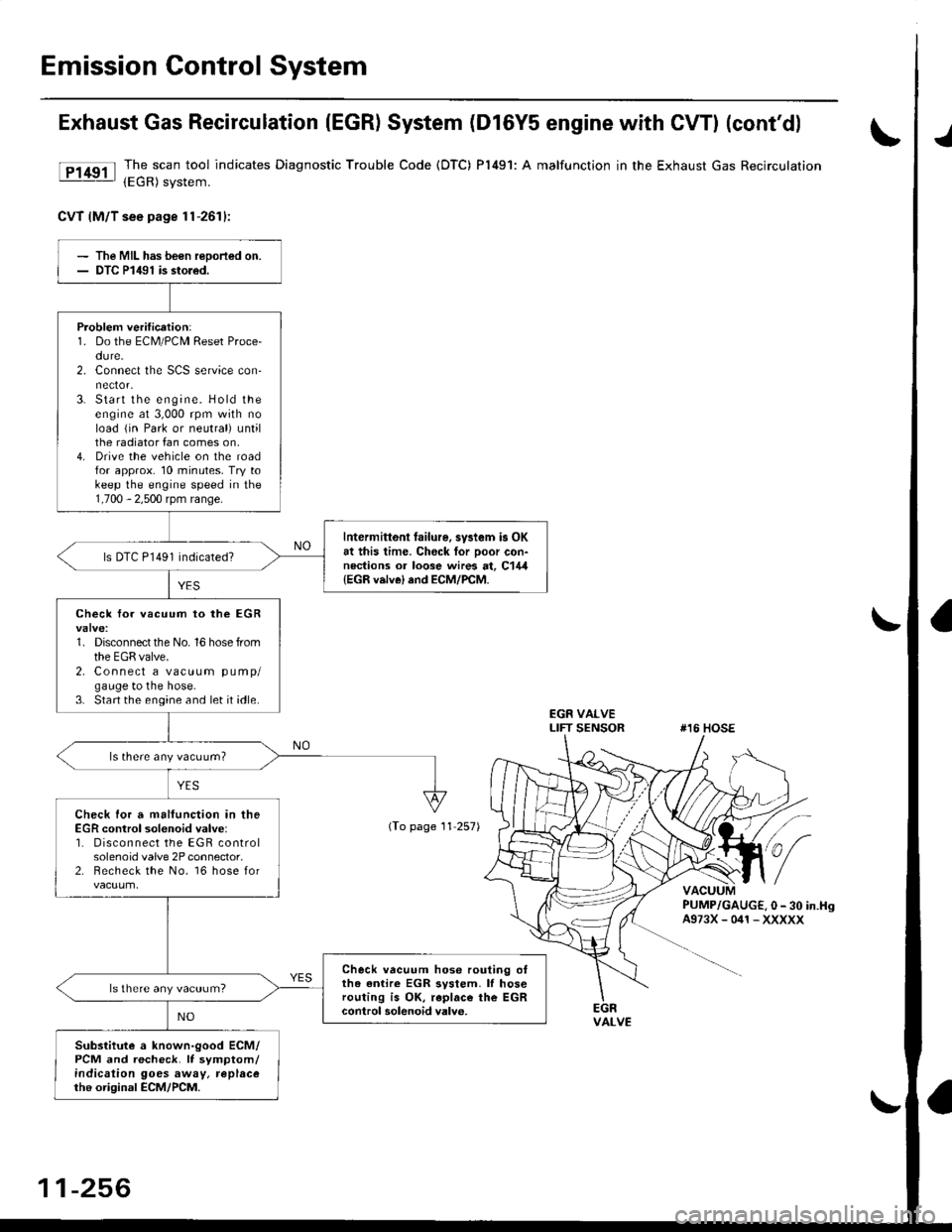
Emission Control System
Exhaust Gas Recirculation (EGR) System (D16Y5 engine with GWI (cont'dl
lTl49il T_he scan tool indicates Diagnostic Trouble Code (OTC) P1491: A malfunction in the Exhaust Gas Recirculation- lEgh) svstem.
CvT lM/T see page 1l-2611:
J
EGR VALVELIFT SENSOR#16 HOSE
PUMP/GAUGE,0- 30 in.HsA973X-041-XXXXX
EGRVALVE
The MIL has been reoorted on.DTC P1491 is stoled.
Problem verification:1. Do the ECM/PCM Reset Proce-du re.2. Connect the SCS service con'
3. Start the engine. Hold theengine at 3,000 rpm with noload {in Park or neutral) untilthe radiator fan comes on,4. Drive the vehicle on the roadfor approx. 10 minutes. Try tokeep the engine speed in the1,700 - 2,500 rpm range.
Intermittonl failure, system is OKat this time. Check for Door con-nections or loose wires at, C144{EGR velve} and ECM/PCM.
ls DTC P l49l indicated?
Check fo. vacuum to ihe EGR
1. Disconnect the No. 16 hose fromthe EGR valve.2. Connect a vacuum pump/gauge to the hose.3. Start the engine and let it idle.
ls there any vacuum?
Check tor a malfunction in theEGR control solenoid valve:'1. Disconnect the EGR controlsolenoid valve 2P connector,2. Becheck the No. 16 hose for
Check vacuum hose routing o,the entire EGR svstem. lf hoserouting is OK, replac€ the EGRcontrol solenoidvalv6.
ls there any vacuum?
Substitute a known-good ECM/PCM and recheck. It symptom/indicalion goes away, replacethe original ECM/PCM.
(To page 11 257)
11-256
Page 526 of 2189
![HONDA CIVIC 1996 6.G Workshop Manual \EGR VALVELIFT SENSOR#16 HOSE
I
(From page 11-256)
EGR VALVE LIFT SENSOR3P CONNECTOR lC14.l)
zF vcczI- . ] IYEL/BLU)ll 2l3l---l-r_ 7 |
v-,, ISG2IGRN/BLK) I ^ II{Vts
ECM CONNECTOR D {16P)
PUMP/GAUGE,0 HONDA CIVIC 1996 6.G Workshop Manual \EGR VALVELIFT SENSOR#16 HOSE
I
(From page 11-256)
EGR VALVE LIFT SENSOR3P CONNECTOR lC14.l)
zF vcczI- . ] IYEL/BLU)ll 2l3l---l-r_ 7 |
v-,, ISG2IGRN/BLK) I ^ II{Vts
ECM CONNECTOR D {16P)
PUMP/GAUGE,0](/img/13/6068/w960_6068-525.png)
\EGR VALVELIFT SENSOR#16 HOSE
I
(From page 11-256)
EGR VALVE LIFT SENSOR3P CONNECTOR lC14.l)
zF vcczI- . ] IYEL/BLU)ll 2l3l---l-r_ 7 |
v-,, ISG2IGRN/BLK) I ^ II{Vts
ECM CONNECTOR D {16P)
PUMP/GAUGE,0 - 30 in.Hs4973X-041-XXXXX
sG2(GRN/BLKIvcc2IYEL/BLU}
Wire side ol temale terminals
PCM CONNECTORS C (31P}'
YES
Wire side of female terminals
1
(cont'd)
1-257
Check fo. a mallunction in theEGF valv€:1. ldove the vacuum pump/gauge
to the EGR valve.2. With the engine at idle, apply
26.7 kPa (200 mmHg,8.0 in.Hg)
ofvacuum to the EGR valve.
Does the engine stall or runrough and does the EGR valvehold vacuum?
Check for an open in the wire
IVCC2linel:1. Turn the ignition switch OFF.2. Disconnect the EGR valve liftsensor 3P connector.3. Turn the ignition switch ON (ll).
4. Measure voltage between theEGR valve lift sensor 3P con'
nector terminals No. 3 and
No.2.
ls lhere approx.5 V?
Check for an oDen in the wire
{VCC2 line}:Measure voltage between theECM/PCM connector terminalsD10 and Dl1 (C18 and C28)*.
Rep.ir open in the wire betweenrhe EGR valve snd ECM/PCM
{Dl0 {C28)*).lsthere approx.5 V?
Sub3titute t known-good ECM/PCM end recheck. lt 3ymptom/indication goos eway, replaceth6 original ECM/PCM.(To page 1l-258)*: '99 - 00 models
Page 527 of 2189
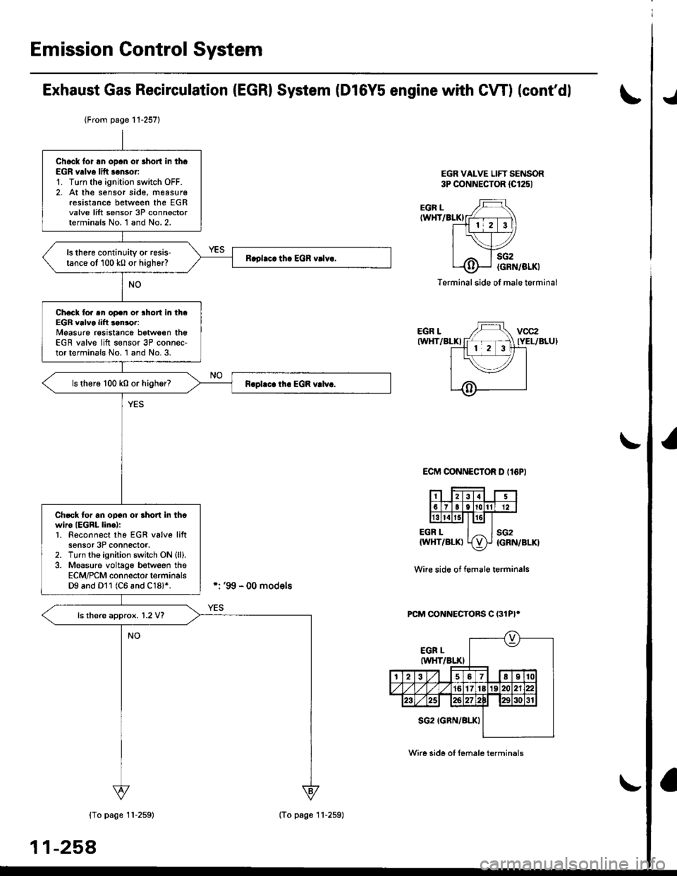
Emission Gontrol System
Exhaust Gas Recirculation (EGRI System (Dl6Y5 engine with CW) (cont'dl
EGR VALVE LIFT SENSOR3P CONNECTOR {Cl251
./
EGR L(WHT/BLKI
EGR LIWHT/BLKI
EGR L{WHT/BLKI
sG2
{GRN/BLK}
sG2{GRN/BLK}
Terminal side ol male terminal
ECIT'I CONNECTOR D II6PI
Wir€ side of f€male terminals
PCM CONNECTORS C (31PI*
{To page 11-259)
11-258
{From page 11-257}
Chock lor an opcn or short in th.EGR v.lve lift .€nsor'1. Turn the ignition switch OFF.2. At the sensor sid€, measur€resistance between the EGRvalve lift sensor 3P connectorterminals No. 1 and No.2.
ls there continuity or resis'tance ot 100 k0 or higher?
Chock tor sn op€n or lhort in theEGR valve lift lonror:Measure resistancg between theEGR valve lift s€nsor 3P connec-tor terminals No. 1 and No. 3.
ls there 100 k0 or higher?
Ch.ck tor an ooon or rhon in thcwiro IEGRL linc):1. Beconnect tho EGR v6lve liftsensor 3P connector.2. Turn tho ignition switch ON (ll).
3. Measure voltage between theECM/PCM connector terminalsD9 and Dl1 (C6 and C18l*.
ls there approx. 1.2 V?
(To page 11-259)
Wire side of female terminals
Page 528 of 2189
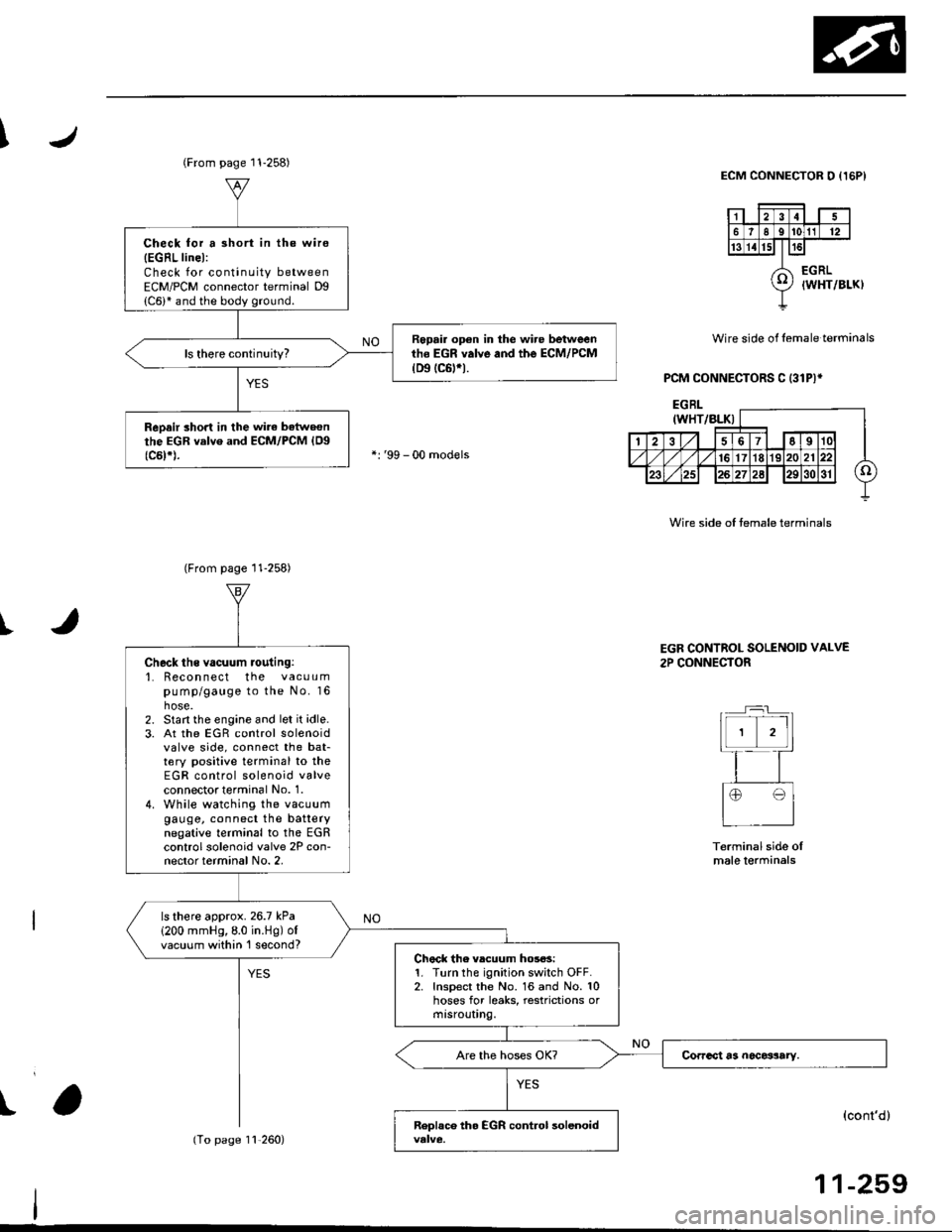
I
I
Wire side of lemale terminals
PCM CONNECTORS C (31P)*
ECM CONNECTOR O {I5PI
Wire side of temale terminals
t
(From page 11-258)
Check for a 3hort in the wire
{EGRL linel:Check for continuity betweenECM/PCM connector terminal Dg
Repair op€n in the wire betweenth6 EGR valve and the ECM/PCM(D9 tc6trt.
ReDair short in the wirc batweonthe EGR valve and ECM/PCM {Og(c5t*).
(From page 11-258)
11,260)
Check ths vacuum routing:'1. Recon nect the vacuumpump/gauge to the No. 16hose.2. Start the engine and let it idle.3. At the EGR control solenoidvalve side, connect the bat-tery positive terminal to theEGR control solenoid valveconnectot terminal No. 1.4. While watching the vacuumgauge, connect the batterynegative terminal to the EGRcontrol solenoid valve 2P con-nector terminal No. 2,
ls there approx.26.7 kPa
1200 mmHg,8.0 in.Hg) ofvacuum within 'l second?Chock the vlcuum hos6s:1. Turn the ignition switch OFF.2. Inspect the No. 16 and No. 10hoses for leaks, restrictions ormtsrouUng.
EGR CONTROL SOLENOID VALVE
2P CONNECTOR
Terminal side oImale lerminals
(cont'd)
11-259
Page 529 of 2189
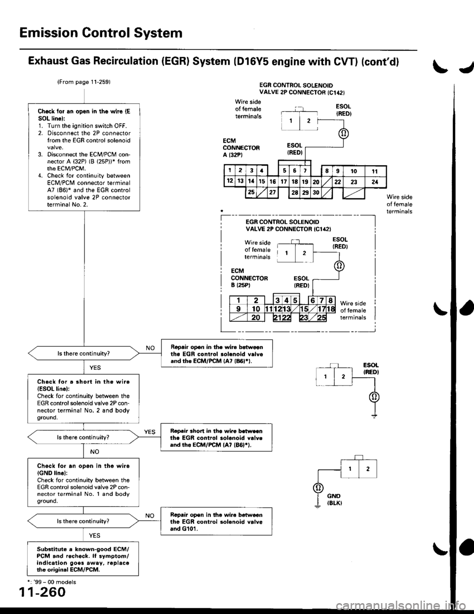
Emission Control System
Exhaust Gas Recirculation (EGR) System (Dl6Y5 engine with CW) (cont'dl
tJ
(From page 11-259)EGR CONTROL SOLENOIDVALVE 2P CONNECTOR {C142}
Wire sideof lemaleterminals
ECMCONNECTORa t32Pl
Chock lor an open in the wire (E
SOL linsl:1. Turn the ignition switch OFF.2. Disconnect the 2P connectorIrom the EGR control solenoid
3. Disconnect the ECN4/PCM con-nector A (32P) (B (25P))* fromthe EcM/PCM.4. Check tor continuity betweenECM/PCl, connector terminal47 (86)* and the EGR controlsolenoid valve 2P connectorterminal No.2.
Repair opon in th. wir. bstwocntha EGR control 3ol€noid valvoand tho ECM/PCM (A7 186l'1.
ls there continuity?
Check for . rhort in the wire(ESOL linel:Check for continuity between theEGR controlsolenoid valve 2P con-nector terminal No. 2 and bodyground,
R.p.ir ahort in tha wi.c b.twecnthe EGR control iolonoid vllyeand th. ECM/FCM {A7 (46}rl.
Check for an opon in the wiroIGND linel:Check for continuity between theEGR controlsolenoid vaive 2P con-nector terminal No. I and bodyground,
Rcpai. op€n in the wir6 b6'twoenthe EGR control rol.noid valveand G101.
Sub3titule a known-good ECM/PCM and rechock. lf symptom/indication goes away, replac€the original ECM/PCM.
ESOL
IRED)
ESOLIRED)
Wire sideof femaleterminals--_-]
I
EGR CONTROL SOLENOIDVALVE 2P CONNECTOR ICl'2}
Wire sideof femaleilterminals
ECMCONNECTORB l25P)ESOL(REDI
Wire sideof femalerermtnats
*: '99 - 00 models
11-260
Page 532 of 2189
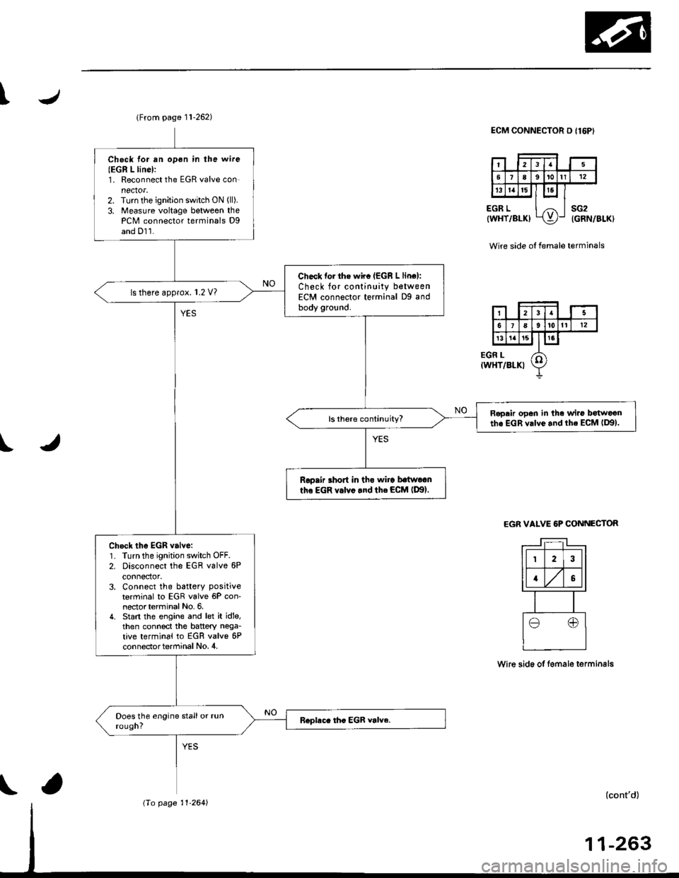
T
t
lFrom page 11-262)
Chock for rn opon in the wire
{EGR L linel:1. Reconnect the EGR valve connector.2. Tu.n the ignition switch ON (ll).
3. Measure voltage betweon thePCM connector terminals Dgand Dl1.
Check tor th€ wirc (EGR L line):
Check for continuity betweenECM connector terminal Dg andbody ground.
ls there approx. 1.2 V?
Roprir op6n in the wirs botweanthe EGR valvo.nd th. ECM lD9).
Rooair ahort in tho wiro baftr,otn
tho EGR v.lv..nd the ECM lDgl.
Ch€ck the EGR valve:1. Turn the ignition switch OFF.2. Disconnect the EGR valve 6P
connector.3. Connect the battery positive
terminal to EGR valve 6P con-nectorterminal No. 6.4. Stan the engine and let it id'e,then connect the battery nega_
tive terminal to EGR valve 6Pcon nector term inal No, 4,
ECM CONNECTOR D I16P'
Wire side oI female terminals
EGR VALVE 6P CONNECTOR
wire sid6 of lemale te.minals
(cont'd)