1 page HONDA CIVIC 1996 6.G Workshop Manual
[x] Cancel search | Manufacturer: HONDA, Model Year: 1996, Model line: CIVIC, Model: HONDA CIVIC 1996 6.GPages: 2189, PDF Size: 69.39 MB
Page 427 of 2189
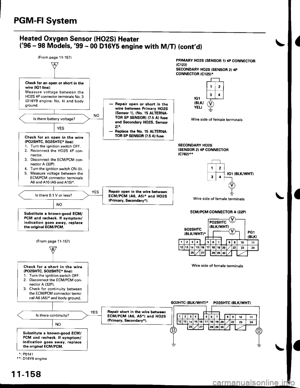
PGM-FI System
a
a
Heated Oxygen Sensor (HO2S) Heater
('96 - 98 Models,'99 - 00 D16Y5 engine with M/T) (cont'dl
PRIMARY HO2S {SENSOR 1I 4P CONNECTOR{c1231SECONDARY HO2S {SENSOR 2} 4PcoNNECTOR 1C125)r
r-l --'1
ll i2l
f;T;ttcl|BLK/ &)YELI Y
Wire side of fomale lerminals
SECONDARY HO2SISENSOR 2) 4P CONNECTOR{c78ilf
IBLK/WHT)
Wire side of lemale terminals
(From page 11-157)
Wire sid€ ot temale terminals
SO2HTC(BLK/WHTI* PO2SHTC{BLK/WHTI
*: P0141*+: Dl6Y8 engine
11-158
(From page 11-157)
Check tor an op6n or 3hoft in thewire {lGl lin6):Measure voltage between theHO2S 4P connector terminals No.3(D16Y8 engine: No. 4) and bodyground.- Repair open or shon in thewire between Primary HO2Slson.or 1), {No. 15 ALTERNA-TOR SP SENSORI (7.5 Al fuseand Secondary HO2S, Sonsol2t,.- Replace the No. 15 ALTERNA-TOR SP SENSOR 17.5 A) tuse.Check for an open in the wireIPO2SHTC, SO2SHTC' linel:1. Turn the ignition switch OFF.2. Reconnect the HO2S 4P con-nector.3. Disconnect the ECM/PCM con-nector A (32P).
4. Turn the ignition switch ON (ll).
5. Measure voltage between theECM,/PCM connector terminals46 and 410 {A5 and A10)*.
Ropail opan in the wire b€twoenECM/PCM lA6, A5l* and HO2S{Primary, Secondary+1.
ls there 0.1 V or less?
Substitute a known-good ECM/PCM and recheck. ll symptom/indication goes awry, repbcetho origin.l ECM/PCM.
ECM/PCM CONNECTOR A I32P)
so2sHrc ItBLK/WH0.J
pozsxtc E/
IBI-K/WHTI ^,-----{v}-|.=,|I
PG1IBLK}3u I JsTgT roll12r3t5t6Ittar920z2l 2321
25272A2i3o
Check tor a short in the wire{PO2SHTC. SO2SHTC* line):'1. Turn the ignition switch OFF.2. Disconnect the ECM/PCM con-nector A (32P1.
3. Check for continuity betweenthe ECM/PCM connector termi-nal 46 (A5)* and body ground.
Repair short in thg wire betwe€nECM/PCM lA6, A5*l .nd HO2S(P.im.ry, Socondary*).
Substitute a known-good ECM/PCM and recheck. It symptom/indicetion goes away, rophcethe original ECM/PCM.
Page 428 of 2189
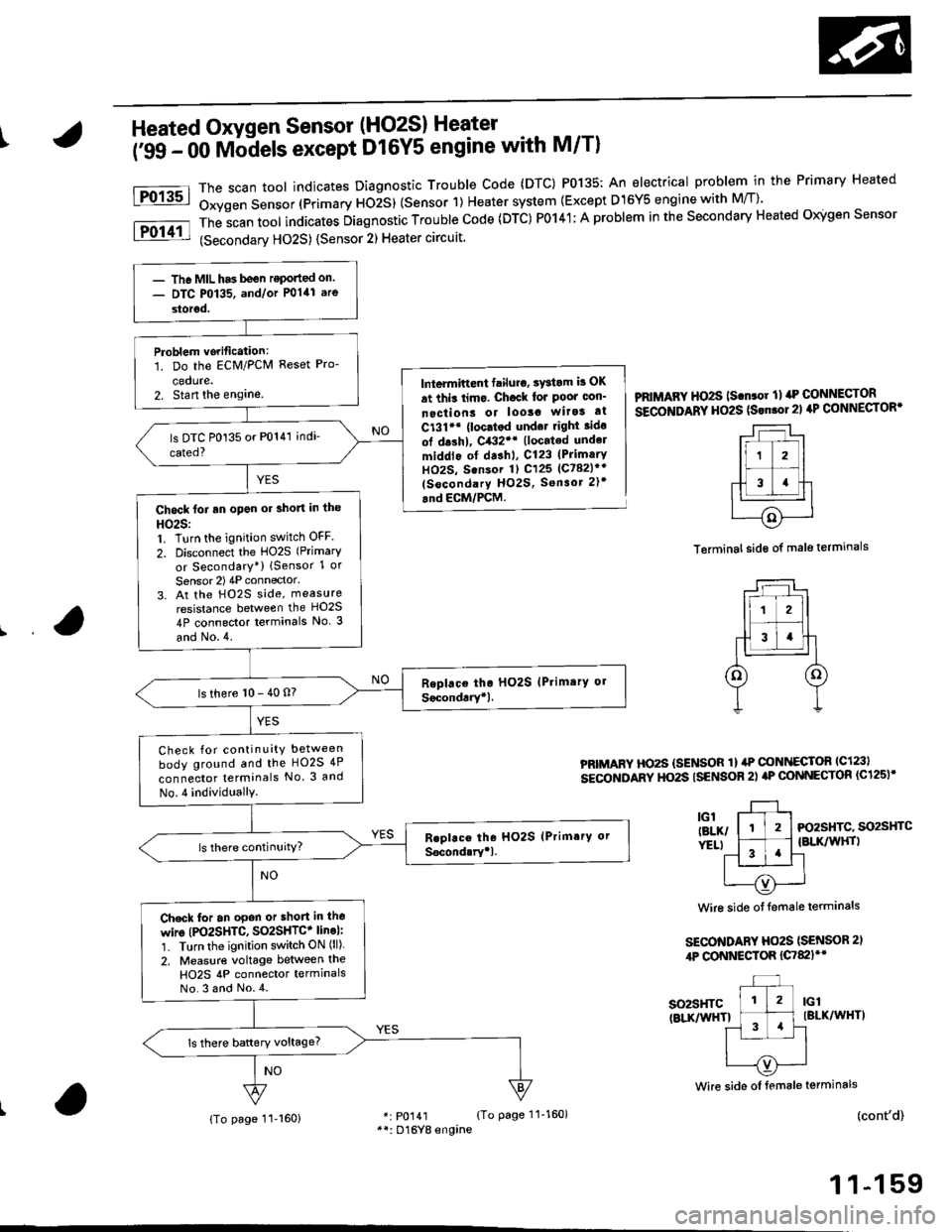
IHeated Oxygen Sensor (HO2S) Heater
i'ss - oo Mb-dels except D16Y5 engine with M/Tl
The scan toot indicates Diagnostic Trouble Code (DTC) P0135: An electrical problem in the Primary Heated
Oxygen Sensor (Primary ttOiS) (Sensor 1) Heater system {Except D15Y5 engine with M/T)'
The
-scan tool indicates Diagnostic Trouble Code (DTC) P0141; A problem in the Secondary Heated Oigen Sensor
(Secondarv HO2S) {Sensor 2) Heater circuit
Fo13sl
Fol11l
lntermiftent failuro, sYstom b OK
at thit limo. Ch6ck lor Poor oon'
nectiont or looso wita! at
C131'* {loc.tod und.t right ido
ol drshl, C432'* (located undel
middlo of dashl, C123 (PrimarY
HOzS, Sensor 1) C125 (Ct82lr'
(socondary HO2S, Sensor 2)t
.nd ECM/PCM.
PRIMAFY HO2S ls.n.or ll rrP CONNECTOR
SECOITIDARY HO2S (Srn.ol21 4P CONNECTOR'
Terminal side of male terminals
PRIMARY HO2S {SENSOR 1} ilP @NI{ECTOR lc123l
sEcoNDARY HO2S ISENSOR 2) aP @NNECTOR (C125)'
3l-, l-tl-t Fo2sHrc. so2sHrc
ver.t l ^-1 .'l {BLK/wHrl
11 '!'l-l
| --=- Iu----{v)'---..-'
Wire side of {emale terminals
SECO'TIDARY Ho2S (SENSOR 2,
4P CONNESTOR {C7&llt'
so2sHTc(BLKnflHTlIBLK/WHT)
(cont'd)
1 1-159
Wire side oI female terminals
r: p0141 {To page 11-160}**: D16Yg engine
- The MIL has been reponed on.- DTC P0135. and/or P0141 are
storod.
Problem vorification:1. Do the ECM/PCM Reset Pro-
cedute.2. Stan the englne.
Chock foi an open or short in the
HO25:1. Turn the ignition switch OFF
2. Disconnect the HO2S (Primary
or Secondary*) lSensor 1 or
Sensor 2) 4P connector'
3. At the H02S side, measure
resistance between the HO2S
4P connector terminals No. 3
and No.4.
ls there 10 - 40 n?
Check for continuity between
body ground and the HO2S 4P
connector terminals No. 3 and
No.4 individuallY.
Check for an opon or short in lho
wire (PO2SHTC, SO2SHTC+ line):'1. Turn the ignition switch ON (ll).
2. Measure voltage between the
H02S 4P connector termlnalsNo.3 and No.4.
{To page 11-160}
Page 429 of 2189
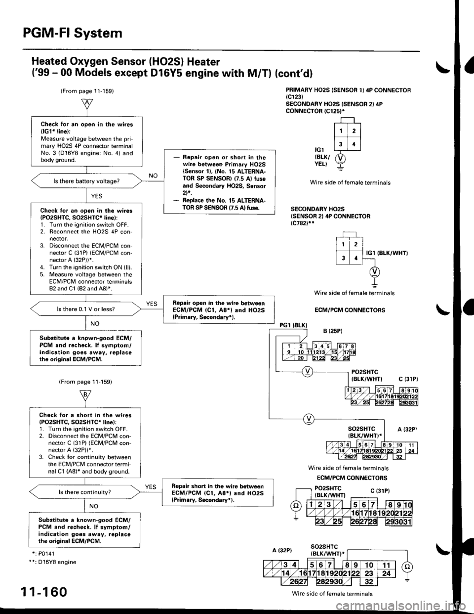
PGM-FI System
Heated Oxygen Sensor (HO2S) Heater
('99 - 00 Models except D16Y5 engine with M/T)
(From page 11-159)
Substitute a known-good ECM/PCM and recheck. lf symptom/indication goes away, replacethe origin.l ECM/PCM.
(cont'dl
PRIMARY HO2S ISENSOR 1I 4P CONNECTOB{c123)SECONDANY HO2S ISENSOR 2} 4PcoNNECTOR (C125)*
-r--r ,
lr zl
-f-13 4llc'l L--r-J-r
relxr p1YELI Y
Wire side of temale terminals
SECONDARY HO2S(SENSOR 21 4P CONNECTOR{c782}rr
IG1 IBLK/WHT)
NO
Wire side of female telminals
ECM/PCM CONNECTORS
Wire side of female terminals
ECM/FCM CONNECTORS
*: P0141**: Dl6Y8 engine
1 1-1 60
Check for an open in the wires{lGl* line}iMeasure voltage between the primary HO2S 4P connector terminalNo. 3 (D16Y8 engine: No. 4) andbody ground.- Repeir open or shon in thewire between Primary HO2Slsensor 1), {No. 15 ALTERNA-TOR SP SENSOR) (7.5 A) fus€and Secondary HO2S, Sensor2t,.- ReDlace the No. 15 ALTERNA-TOR SP SENSOR {7.5 A tuse.
ls there battery voltage?
Check ,or an open in the wires(PO2SHTC, SO2SHTC' linel:1. Turn the ignition switch OFF.2. Reconnect the HO2S 4P con-nector,3. Disconnect the ECN4/PCM connector C (31Pi (ECM/PCM con-nector A (32P))i.
4. Turn the ignition switch ON (lli.
5. Measure voltage between theECM/PCM connector terminals82 and Cl 182 and AB)*.
Reprir open in the wirc betwo€nECM/PCM (Cl, A8i) and HO2S(Primary, Secondary+).
ls there 0.1 V or less?
(From page 11 l59i
Check tor a short in the wiresIPO2SHTC, SO2SHTC* linel:1. Turn the ignition switch OFF.2. Disconnect the ECM/PCM con-nector C (31Pi (ECM/PCM connector A (32P)i*.
3. Check tor continuity betweenthe ECM/PCM connector terminal C1 {A8)* and body ground.
Repai. short in the wire b€tweenECM/PCM lcl, A8.l and HO2S(Pdmery, Secondary*1.
Substitute a known-good ECM/PCM end recheck. lf symptom/indication goes away, replacethe o.iginal ECM/PCM.
Wire side of female terminals
Page 430 of 2189
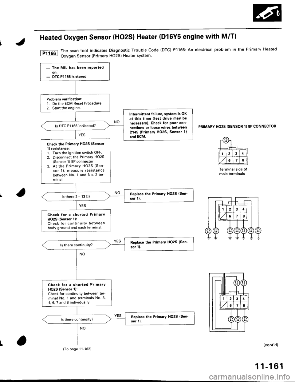
Heated Oxygen Sensor (HO2SI Heater (Dl6Y5 engine with M/Tl
The scan tool indicates Diagnostic Trouble Code (DTC) P1166: An electrical problem in the Primary Heated
Oxygen Sensor (Primary H02S) Heater system.
PRIMABY HO2S ISENSOR 1I 8P CONNECTOR
Terminal side ofmale terminals
I(cont'd)
11-161
- The MIL has been lePorted
- DTC Pl166 b stored.
Problem verilication:1. Do the ECM Reset Procedure.
2. Start the engine.
Intermitlent failura, sYstem b OK
at this time (te3t drive maY be
ngcessary). Check for poor con-
nections or loose wires between
C145 (Primary HO2S, Sen3or 1l
end ECM.
ls DTC P'l166 indicated?
Check the Primary HO2S (Sensot
1l resistence:1. Turn the ignition switch OFF
2. Disconnect the Primary HO2S(Sensor 1) 8P connector.
3. At the Primary HO2S (Sen
sor 1), measure resistance
between No. 1 and No. 2 ter_
Replace lhe Primery HO2S (Sen-
sor 11.ls there 2 13 O?
Check for a shorted PrimarY
HO2S lsensor 1):Check for continuity between
body ground and each terminal.
Check for a shorted PrimarY
HO2S {S€nsor 1l:
Check for continuity between ter'
minal No. 1 and terminals No.3,
4, 6, 7 and 8 individually.
ls there conlrnuily?
(To page 11'162)
Page 431 of 2189
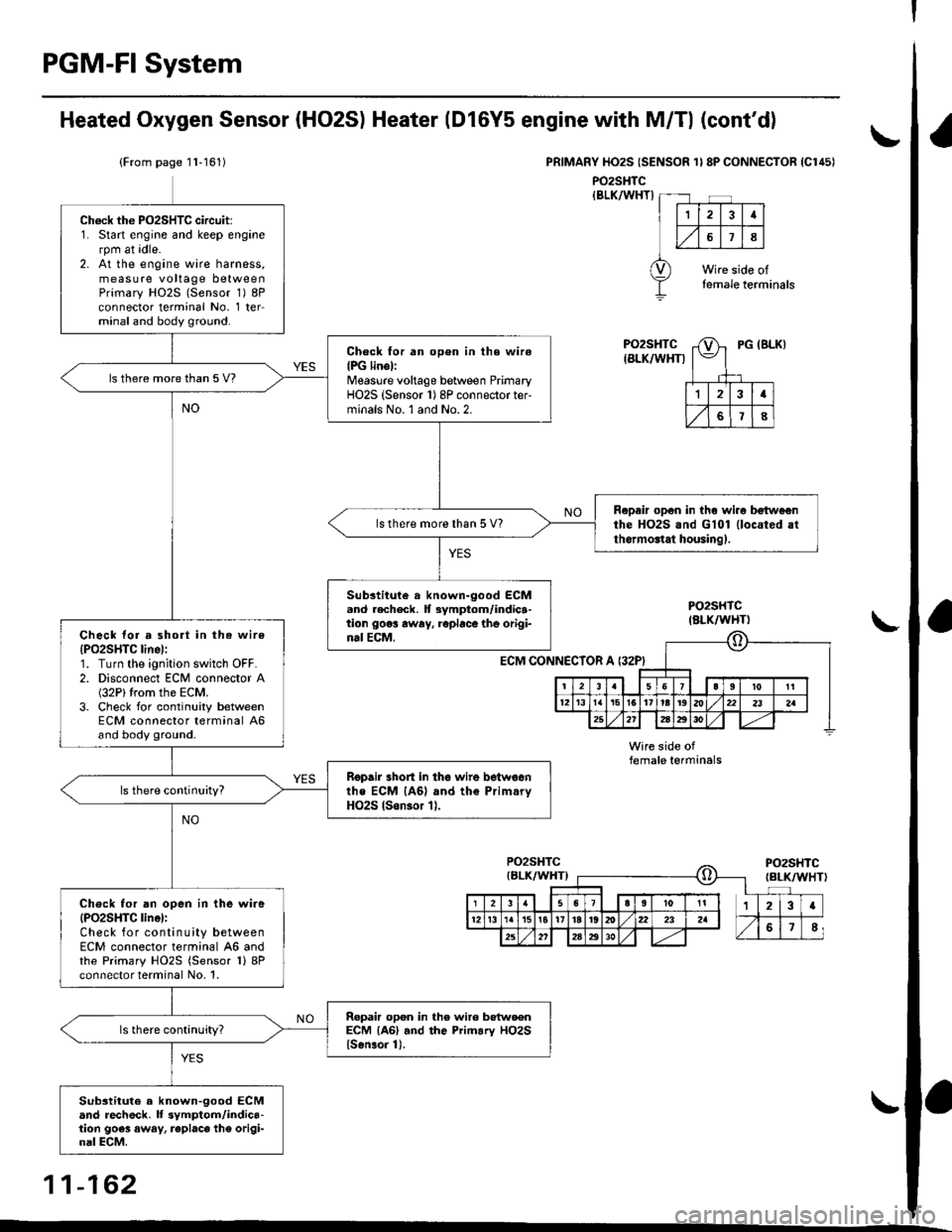
PGM-FI System
I
a
a
Ch6ck the PO2SHTC circuit:1. Start engine and keep enginerpm at idle.2. At the engine wire harness,measure voltage betweenPrimary HO2S (Sensor 1) 8Pconnector terminal No. 1 terminal and body ground.
Check for an open in the wire(PG linellMeasurc voltage between PrimaryHO2S (Sensor 1) 8P connector ter-minals No. l and No.2.
ls there morethan 5 V?
Repair opon in the wi.o bEtwoonthe HO2S.nd G101 (located atth.rmonat housingl.
ls there more than 5 V?
Substitule a known-good ECM.nd .echeck. lt 3ymptom/indica-tion 906! rwry, roplace the origi-nal ECM,Check lor a short in the wire
{PO2SHTC line):1. Turn the ignition switch OFF.2. Disconnect ECM connector A(32P)trom the ECM.3. Check for continuity betweenECM connector terminal 46and body ground.
Ropair 3hort in tho wire betwoenthe ECM {46} and the Prim.ryHO2S lson3or 11.
Check for an open in the wire(PO2SHTC linel:Check for continuity betweenECM connector terminal 46 andthe Primary HO2S (Sensor 1)8Pconnector terminal No. 1.
Repair opsn in the wir6 botweenECM {A6} .nd the Primary HO2Slsonror 1).
Substituto a known-9ood ECMand rech6ck. lf symptom/indica-tion goes away, replace the origi-nal ECM.
Heated Oxygen Sensor (HO2S) Heater (Dl6Y5 engine with M/Tl (cont'd)
(From page 11-161)PRIMARY HO2S (SENSOR 1} 8P CONNECTOR {Cl45I
PO2SHTC{BtK/WHT)
PO2SHTCIALK/WHTI
ECM CONNECTOR
female terminals
11-162
\.
!
\
A {32P}
o
6I9l roIt
12t3l5t61't8t9a221 232a
252'2aEito,1| ---
Page 437 of 2189
PGM-FI System
Misfire in Detected One Gylinder (cont'dl
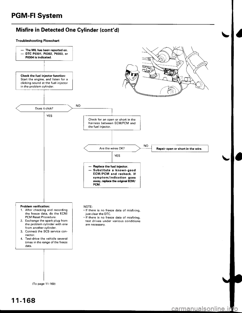
Troubleshootin g Flowchart
NOTE:. lf there is no treeze data of misfiring,just clear the DTC.. It there is no freeze data of misfiring,test drives under various conditions
- The MIL has been reoorted on.- DTC P0301. P0302. P0303, orP030il is indicated.
Check the fuel iniecto. lunction:Stan the engine, and listen for aclicking sound at the fuel injectorin the problem cylinder.
Check for an open or short in theharness between ECM/PCM andthe fuel iniector.
Repair open or short in the wir€.
Replace the fuel iniector.Sub3titute a known-goodECM/PCM and recheck. Itsymptom/indication goesaway, replace the original ECM/PCM.
Problem verification:1. After checking and recordingthe freeze data, do the ECM/PCM Reset Procedure.2. Exchange the spark plug fromthe problem cylinder with onefrom another cylinder,3. Connect the SCS service con'nector,4. Test-drive the vehicle severaltimes in the range ofthe free2edata.
(To page 11-169)
1 1-1 68
Page 438 of 2189
I
ll
t
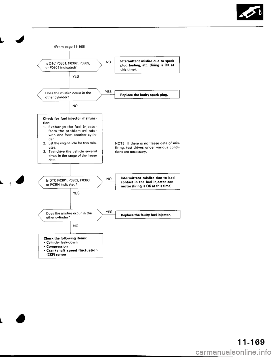
NOTE: lf there is no freeze data of mis_
firing, test drives under various condi
tions are necessary.
(From page 11'168)
Intermittent misfire due to sparkplug fouling, etc. (firing is OK arthis time).
ls DTC P0301, P0302, P0303,or P0304 indicated?
Does the misfire occur in theother cylinder?Replace the faulty spark plug.
Check for fuel iniector mallunc-
l|on:1. Exchange the fLrel injectorfrom the problem cylinderwith one from another cylinder.2. Let the engine idle for trrvo min-
utes.3. Test-drive the vehicle severaltimes in the range ot the freeze
data.
lntermitt€nt mistire due to badcontact in the fuel iniector con-nector (firing is OK at this time).
ls DTC P0301, P0302, P0303,or P0304 indicated?
Does the mistire occur in theother cylinder?Replace the taulty fuel injector.
Check lhe following items:. Cylinder leak-down. Compression. Crankshatt speod tluctuation
{CKF) sensoi
1 1-1 69
Page 442 of 2189
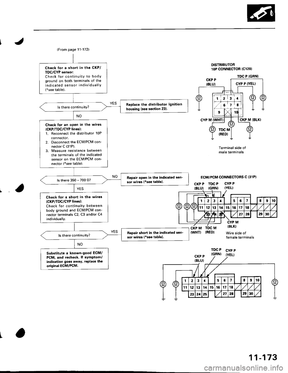
(From page | 1-172)
Check fo. a sho.t in the CKP/
TDC/CYP sensor:Check for continuity to bodYground on both terminals of the
indicated senso r individually
1*see table).
Replaco the di3tributor ignition
hoGing lsee section 23).ls there continuity?
Check for an open in the wires
ICKP/TOC/CYP line3):1. Reconnect the distributor 10P
connecaor.2. Disconnect the EcM/PCM con-
nector C {31P}.3. N4easure resistance betweenthe terminals of the indicated
sensor on the ECIM/PCM con-
nector {*see tabie}.
Repair open in the indicated sen-
sor wires lrsee tablel.ls there 350 - 700 o?
Chock lor. short in the wires
ICKP/TDC/CYP lines):
Check for continuity between
body ground and ECM/PCM con-
nector terminals C2, C3 and/or C4individually.
Repai. short in the indic.ted sen_
sor wire3 ('soe tablol,ls there continuity?
Substitute e known-good ECM/PCM, and iecheck. ll sYmptom/indication goes awev, r€Place the
original ECM/PCM.
DISTRIBUTOR10P CoNNECTOR {C1201
Terminalside ofmale terminals
ECM/PCM CONNECTORS C 131P)
CI(P P TDC P CYP P(YEL)
M
CKP M(WHT)MIBLKI
Wire side offemale terminals
CYP PIYELI
(REDI
TDC P(GRN)CKP P(BLU}
t
TDC P (GRNI
11-173
Page 443 of 2189
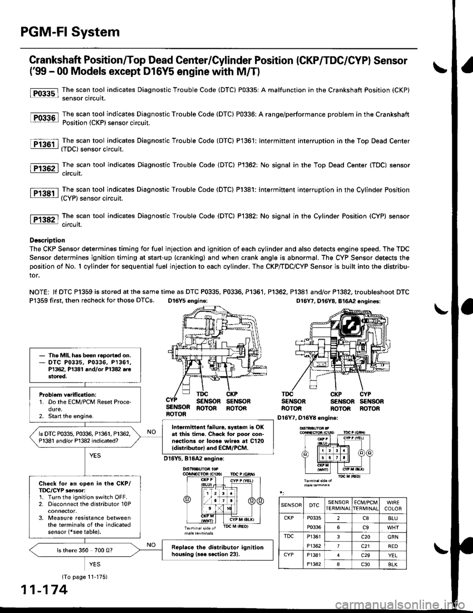
PGM-FI System
l-Fos3sl
tFos36l
tF1361 l
Fr362-1
tF13sil
Crankshaft Position/Top Dead Center/Cylinder Position (CKP/TDC/CYPI Sensor
f99 - 00 Models except D16Y5 engine with M/T)
The scan tool indicates Diagnostic Trouble Code (DTC) P0335: A malfunction in the Crankshaft Position (CKP)
sensor circuit.
The scan tool indicates Diagnostic Trouble Code (DTC) P0336: A range/performance problem in the Crankshaft
Position (CKP) sensor circuit.
The scan tool indicates Diagnostic Trouble Code (DTC) P1361: Intermittent interruption in the Top Dead Center
{TDC) sensor circuit.
The scan tool indicates Diagnostic Trouble Code {DTC) P1362: No signal in the Top Dead Center (TDC) sensor
circuit.
The scan tool indicates Diagnostic Trouble Code (DTC) P1381: Intermittent interruption in the Cylinder Position(CYP) sensor circuit.
lTiaSt The scan tool indicates Diagnostic Trouble Code (DTC) P1382; No signal in the Cylinder Position (CYP) sensor: circuil.
DoscriDtion
The CKP Sensor determines timing for fuel injection and ignition of each cylinder and also detects engine speed. The TDC
Sensor determines ignition timing at start-up (cranking) and when crank angle is abnormal. The CYP Sensor detects the
position of No. 1 cylinder for sequential fuel injection to each cylinder. The CKP/TDC/CYP Sensor is built into the distribu-
tor.
NOTE; lf DTC P1359 is stored at the same time as DTC P0335, P0336, P1361. P1362, P1381 and/or P1382, troubleshoot DTC
P1359 first, then recheck for those DTCS. D16Y5 engino:
SENSORROTOR
TDGSENSORCKPSENSOBTDCSENSOBCKPSENSOBCYPs€NsonBOTORROTORBOTONROTOR ROTOR
D16Y7, D16Y8 ongine:
(To page 11-175)
1-174
- The MIL has been reportod on.- DTC P0335, P0336. P1361,P1362, P1381 rnd/or P1382.restored.
Problem verific{tion:1. Do the ECM/PCM Reset Proce-dure.2. Start the engine.
Intormittcnt failure, systom b OKat thb time. Check to. poor con-nections or loose wires at C120(dktributorl and ECM/PCM.
ls DTC P0335, P0336, P1361, P1362,P1381 and/or Pl382 indicated?
Check tor an open in the CKP/TDC/CYP 3enior:1. Turn the ignition switch OFF.2. Disconnect the distributor 10Pconnector,3. Measure resistance betweenthe terminals of the indicatedsensor (*see table).
Replrce the distributor ignitionhou3ing (!ee section 231.ls there 350 700 0?
SENSORDTCSENSORTEBMINAIECM/PCMTERI\,4INAICOLOR
CKPP0335
P0336
2c88LU
6c9
TDCP1361
P1362
3c20GRN
7c21BED
CYPP1381
P1342
c29YEL
Ic30BLK
Page 444 of 2189
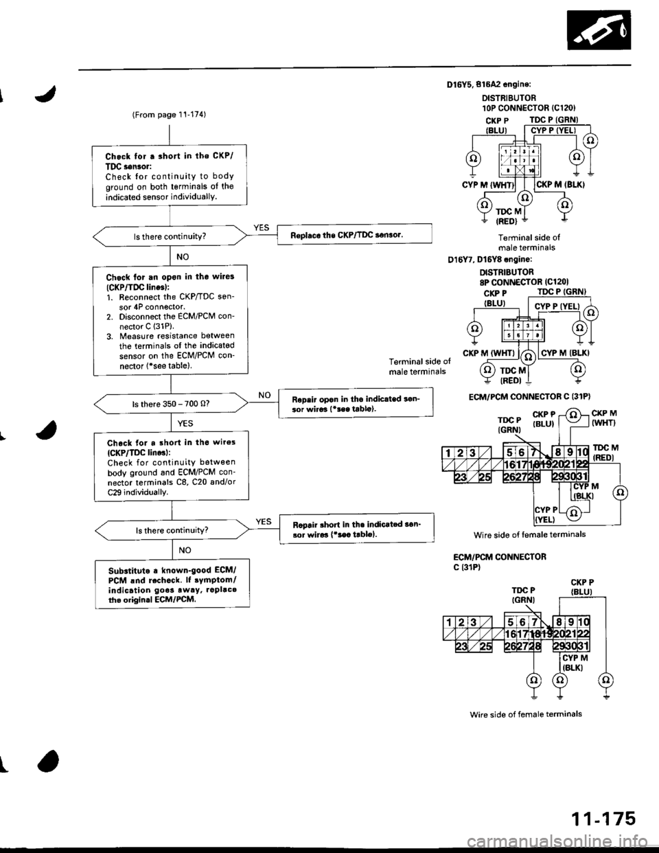
Dl6Y5.816A2 engine:
DISTRIEUTOR
Terminal side olmale terminals
016Y7, Dt6Y8 engine:
DISTRIBUTOR8P CONNECTOR (Cl201
Terminal side olmale terminals
CKP MIWHT}
lDC M(REDI
ECM/PCM CONNECTORc l31P)
wire side of female terminals
t
l0P coNNECTOR {C120)(From page 11-174)
Chock for.3hort in lho CKP/
Tlrc s6n3o.:
Check {or continuity to body
ground on both tsrminals of the
indicated sensor individuallY.
Chsck for an open in the wile3
ICKP/TIrc line6l:1. R€connect the CKP/TDC son-
sor 4P connector.2. Disconnect the ECM/PCM con-
nector C 131P).3. Measure resistance between
the terminals ol the indicated
sensor on the ECM/PCM con-
nector 1*see tablel.
Ropsir opon in tho indiclted son-ior wiro3 l*!sa tabla).ls there 350 - 700 o?
Chack for a .ho in th6 wiros
{CKP/TDC lino3l:Check for continuity between
body ground and ECM/PCM con-
nector terminals C8, C20 and/or
C29 individually.
Rcpair rhort in th. indicat.d 36n_
lor wirar {'3ac trblol.
Substituto . known-good ECM/
PCM lnd rechock. lf 3ymptom/indicatlon go6s aw.y, ropllc.tho origin.l ECM/PCM.
ECM/PCM CONNECTOR C (31P)
Wire side of femsle terminals
CKP P
11-175