1 page HONDA CIVIC 1996 6.G Owners Manual
[x] Cancel search | Manufacturer: HONDA, Model Year: 1996, Model line: CIVIC, Model: HONDA CIVIC 1996 6.GPages: 2189, PDF Size: 69.39 MB
Page 277 of 2189
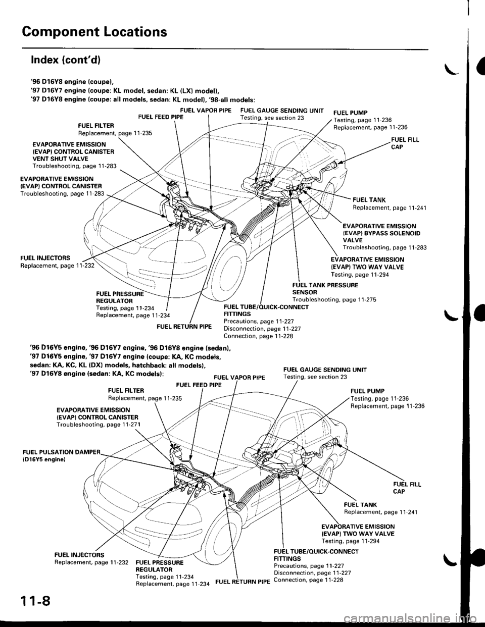
Component Locations
Index (cont'dl
'96 D16Y8 engine (coupel,'97 D16Y7 engine (coupe: KL model, sedan: KL (LXl model),'97 D16Y8 engine (coupe: all models, sedan: KL modell,'98-all models:
FUEI- VAPOR PIPEFUEL FEED PIPEFUEL GAUGE SENDING UNITTesting, see section 23FUEL PUMPTesting, page 11 236Replacement, page 11 236FUEL FILTERReplacement,
€VAPOFATIVE EMISSION(EVAPI CONTROL CANISTERVENT SHUT VALVETroubleshooting, page l1'283
FUEL FILLCAP
FUEL TANKReplacement, page I l-241
EVAPORATIVE EMISSIONIEVAPI CONTROLCANISTERTroubleshooting, page 11 283
EVAPORATIVE EMISSIONIEVAP) BYPASS SOLENOIDVALVETroubleshooting, page 1 1 -283
FUEL INJECTORSReplacement, page 1 1-232EVAPORATIVE EMISSION(EVAPI TWO WAY VALVETesting, page 11 294
FUELREGULATORTesting, page 11-234
TANK PRESSURESENSORTroubleshooting, page 11-275
Replacement, page 1 1-234
'96 Dt6Y5 engine,'96 D16Y7 engin€, '96 D16Y8 engine (sedanl,'97 D16Y5 engine,'97 Dl6Y7 engins (coupe: l(A, KC models,
sedan: KA, KC, KL (DXl models, hatchback: all models),'97 Dl6Y8 engine (sedan: KA, KC modelsl:
FUEL FEED PIPE
FUELFITTINGSPrecautions, page 1 1-227Disconnection, page 11 227Connection, page 11-228
FUEL VAPOR PIPE
FITTINGS
EVAPORATIVE EMISSIONIEVAPI CONTROL CANISTERTroubleshootiog, page 1 1-271
FUEL FILTERReplacement, page 1 1-235FUEL PUMPTesting, page 11-236Replacement, page 11-236
FUEL TANKBeplacement, page 11 241
TIVE EMISSION{EVAP) TWO WAY VALVETesting, page 11-294
TUBE/OUICK.CONNECT
FUEL PRESSUREREGULATORTesting, page 11'234Beplacement, page 11 234
Precautions, page 1 1-227Disconnection, page 11'227Connection, page 1 1-228
11-8
FUEL RETURN PIPE
Page 278 of 2189
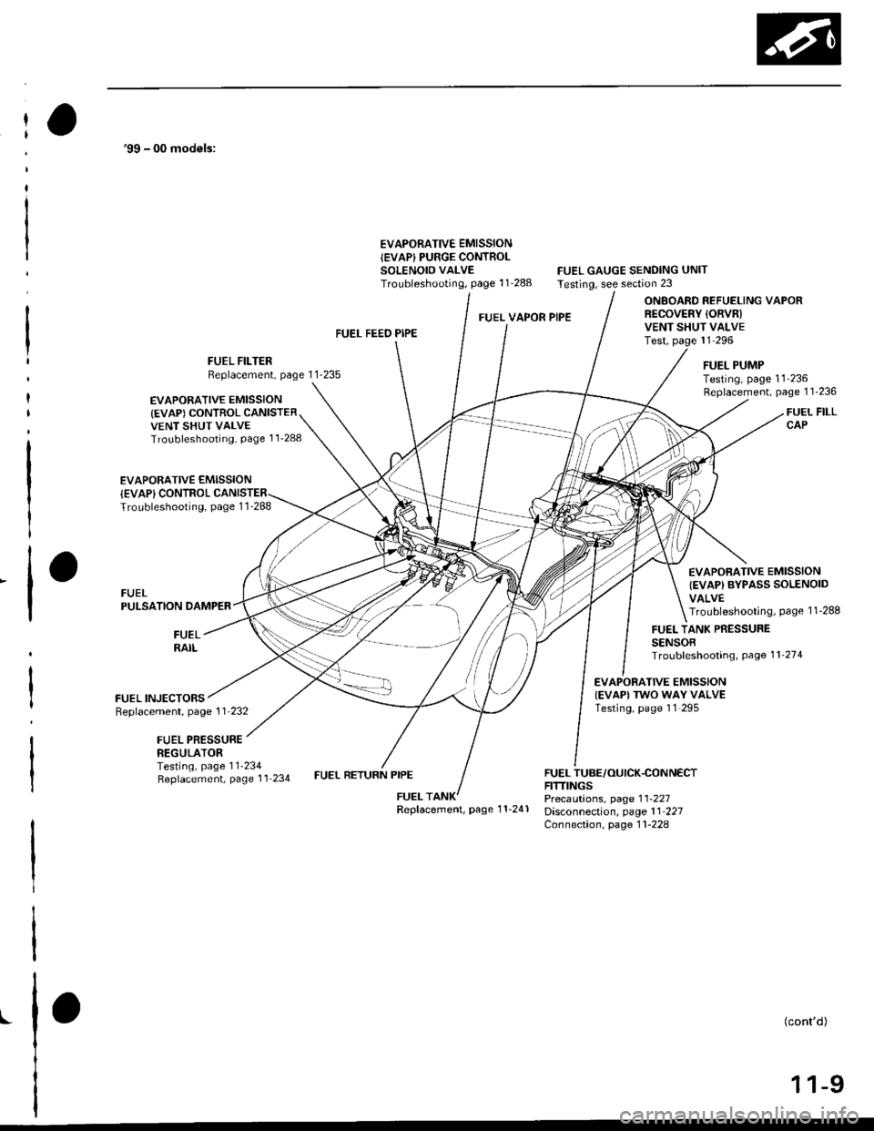
'99 - 00 models:
EVAPORATIVE EMISSIONIEVAP} PURGE CONTROLSOLENOID VALVETroubleshooting, page 1 1'288FUEL GAUGE SENDING UNITTesting, see section 23
FUEL VAPOR PIPE
ONBOARD REFUELING VAPORR€COVERY IORVRIVENT SHUT VALVETest, page 11 296
EVAPORATIVE EMISSION
{EVAP) CONTROL CANISTERVENT SHUT VALVETroubleshooting, Page 1 1_288
EVAPORATIVE EMISSION
FUEL FILTERBeplacement, page 11-235
FUEL FEED PIPE
FUEL RETURN PIPE
FUEI- PUMPTesting, page 11 236Replacement, page 11-236
FUEL FILLCAP
{EVAPI CONTROLTroubleshooting, page 1 1_288
FUELPULSATION DAMPEB
FUEL INJECTORSReplacement, page 1 1'232
FUEL PRESSUREREGULATOR
EVAPORATIVE EMISSION
{EVAP) BYPASS SOLENOIDVALVETroubleshooting, page 1 1-288
FUELRAIL
FUEL TANK PRESSURESENSOBTroubleshooting, Page 1 1'274
EVAPORATIVE EMISSIONIEVAPI TWO WAY VALVETesting, page 11 295
Testing, page 11-234Replacement, page 11 234FUEL TUBE/OUICK.CONNECTFITTINGSPrecautions, page 1 l-227Disconnection, page 11 227Connection, page 1 1-228
Replacement, page 1 1-241
I(cont'd)
1 1-9
Page 279 of 2189
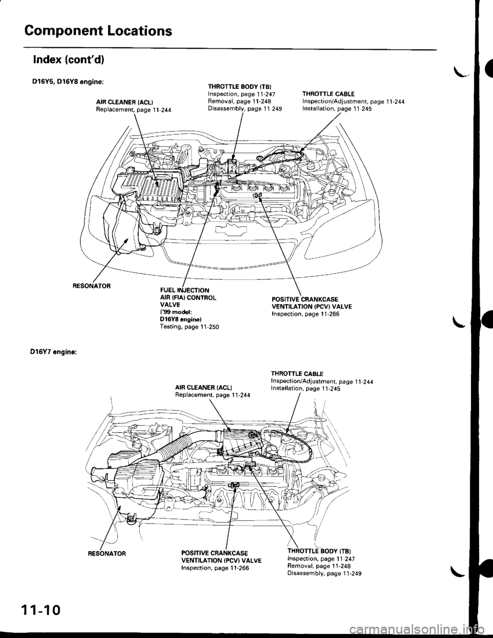
Component Locations
Index (cont'd)
D16Y5, D16Y8 ongine:
RESONATOR
D16Y7 6ngin€:
AIR CLEANER IACLIReplacement, page 11-244
THROTTLE BODY (TBIInspection, page 1 1-247Removal, page 11-248Disassembly, page 11 249
THROTTLE CABLElnspection/Adjustment. page 1 1 -244
Installation, page 11 245
AIR {FIA} CONTROLVAIVE{'99 modeliD16Y8 6ngin6)Testing, page 11,250
POSITIVE CRANKCASEVENTILATION IPCV) VALVEInspection, page 11-266
AIR CLEANER IACLIReplacement, page 11,244
THROTTLE CABITf nspection/Adjustment. page 1 1,244Installation, page 1 1-245
.iBoov ffetInspection, page 11 247Removal, page 11,248Disassembly, page 1 1-249
POSITIVE CRANKCASEVENTILATION IPCVI VALVEInspection, page 1 1-266
1 1-10
RESONATOR
Page 280 of 2189
\-
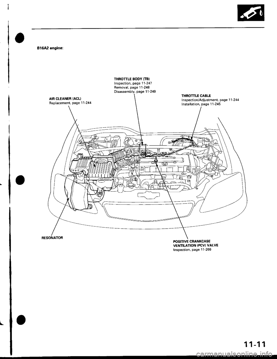
816A2 engine:
AIR CLEANER (ACLI
Replacement, Page 11-244
THROTTLE BODY {T8)Inspection. page 11-247Removal, page 1 '1-248
Disassembly, page 1 1-249THROTTLE CABLElnspection/Adiustment, page 1 1 -244
lnstallation, page 1 1-245
POSITIVE CRANKCASEVENTILATION IPCVI VALVEInspection, page 1 1-266
11-11
Page 350 of 2189
Troubleshooting
Troubleshooting Procedures
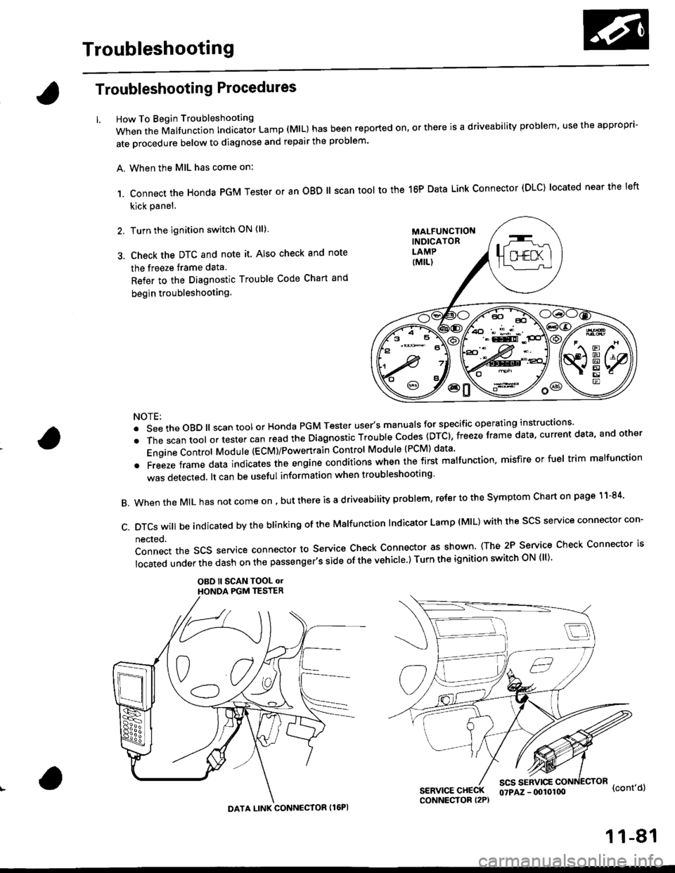
How To Begin Troubleshooting
When the Malfunction Indicator Lamp (MlL) has been reported on, or there is a driveability problem, use the appropr'-
ate orocedure below to diagnose and repair the problem'
A. When the MIL has come on:
,1. connect the Honda PGM Tester or an oBD ll scan tool to the 16P Data Link connector (DLC) located near the left
kick panel.
2. Turn the ignition switch ON (ll)
3. Check the DTC and note it. Also check and note
the freeze trame data
Refer to the Diagnostic Trouble Code Chart and
begin troubleshooting.
NOTE:
.SeetheoBD||scantoolorHondaPGMTesteruser,smanua|sforspecificoperatinginstructions..
.Thescantoo|oltestercanreadtheDiagnosticTroub|ecodes(DTc},freezeframedata,currentdata,andother
Engine Control Module (ECM)/Powertrain Control Module (PCM) data'
oFreezeframedataindicatestheengineconditionswhenthefirstma|function,misfireorfue|trimma|function
was detected. lt can be useful information when troubleshooting'
B. When the MIL has not come on , out there is a d riveability problem, refer to the Symptom Chart on page 1 1-84'
c.DTcswi|lbeindicatedbytheb|inkingoftheMa|function|ndicatorLamp(M|L)withthescsserviceconnectorcon.
nected.
Connect the SCS service connector to Service Check Connector as shown (The 2P Service Check Connector is
|ocatedunderthedashonthepassenger,ssideofthevehic|e')TurntheignitionswitchoN{||)'
OBO ll SCAN TOOL olHONOA PGM TESTER
SERVICE CHECKCONNECTOR I2P)
scs sERvlcE(cont'd)
MALFUNCTIONINDICATORLAMP
DATA LINK CONNECTOR Il6PI
07PAZ - (x)l0100
11-81
Page 352 of 2189
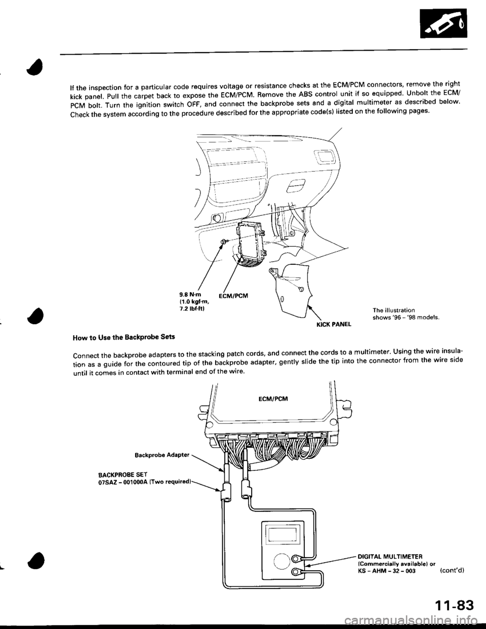
lf the inspection for a particular code requires voltage or resistance checks at the ECM/PCM connectors, remove the right
kick panel. Pull the carpet back to expose the ECM/PCM. Remove the ABS control unit if so equipped. unbolt the EcM/
PCM bolt. Turn the ignition switch oFF, and connect the backprobe sets and a digital multimeter as described below
check the system according to the procedure described for the appropriate code(s) listed on the following pages'
The illustrationshows '96 - '98 models.
How to Use lhe Backprobe Sets
connect the backprobe adapters to the stacking patch cords, and connect the cords to a multimeter. using the wire insula-
tion as a guide for the contoured trp of the backprobe adapter. gently slide the tip into the connector from the wire side
until it comes in contact with terminal end of the wire'
BackProbe
BACKPROEE SET
07SAZ - 001000A lTwo
DIGITAL MULTIMETER(Commercially avail.bleI orKs - AHM - 32 - oo3 (cont'd)
KICK PANEL
1 1-83
Page 353 of 2189
Troubleshooting
Troubleshooting Procedures (cont,dl
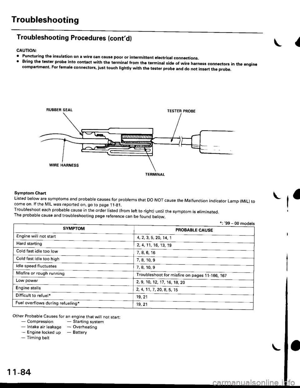
CAUTION:
. Punqturing ihe insulation on a wirs can cause poor or intermiftent electricar connections.I Bring the test€r probe into contacl with the terminatlrom the terminal side of wire harnesg conncctors in the gngin€compartment. For temale connectors, iust touch lightly with the tester probe and do not inse.t the probe.
\I
RUBBER SEAL
Other Probable Causes for an engine that will not start:- Compression- Starting system- lntake air leakage - Overheating- Engine locked up - Battery- Timing belt
TESTER PROBE
Symptom Chart
Listed below are symptoms and probable causes for problems that Do NoT cause the Malfunction indicator Lamp (MlL) tocome on. lfthe MIL was reported on, go to page 11_81.Troubleshoot each probabre cause in the order risted (from reft to right) untir the symptom is eriminated.The probable cause and troubleshooting page reference can be found berow.
L
*: '99 - 00 models
TERMINAL
SYMPTOMPROBABLE CAUSE
4,2,3, 5,20, 14, 1
2, 4, 11, 16, 13, 't9
?, s^6. 16
1,8,10.9
Engine will not sta rt
Hard starting
Cold fast idle too low
Cold fast idle too high
ldle speed fluctuates7,8, 10.9
Troubleshoot for misfire on pages l1-166, 167Misfire or rough running
LOW power
E"g|* "t"lb
2,9, 10, 12, 11, 16, 't8,20
2,4,11,7,20,8,5,15
't9, 21
1r, ,1
Difficult to refuel*
Fuel overflows during refueling*
11-84
Page 354 of 2189
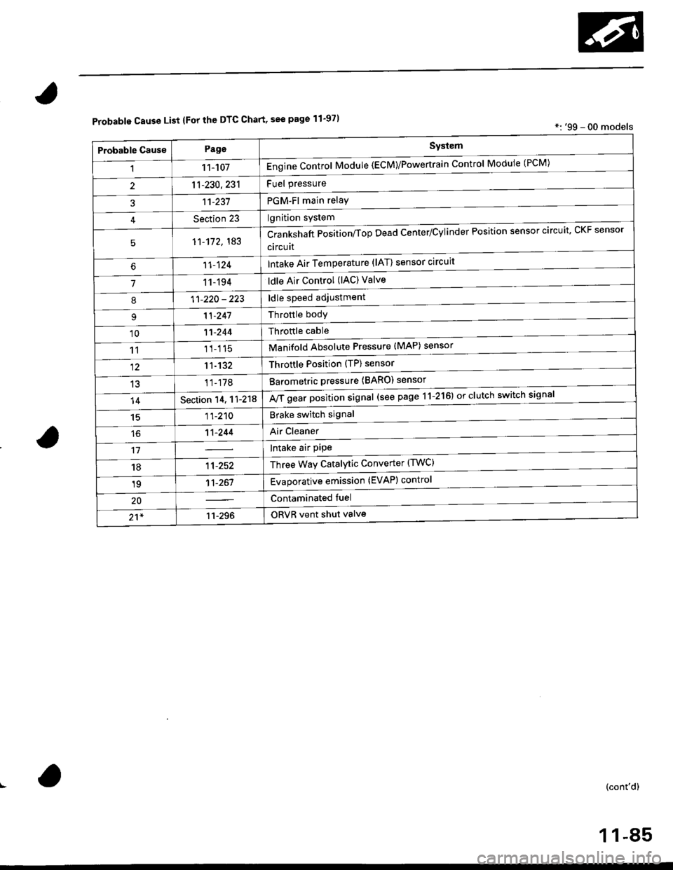
Probable Cause List lFor th€ DTC Chart, see page 11-971*: '99 - 00 models
Probable GausePageSystem
11 1-107Engine Control Module (ECM)/Powertrain Control Module (l'uM)
PGM-Fl main relay
l^^iti^n cwetam
211-230,231
3't't-237
Section 23
51'�1-172,183Crankshaft Position/fop Dead Center/Cylinder Fosltlon sensor clrculr'� Lr\F selrsor
circuit
Intake Air Temperature (lAT) sensor circuit
ldle Air Control (lAC) Valve
ldle speed adjustment
Throttle bodY
Throftle cable
Manifold Absolute Pressure (MAP) sensor
Throftle Position (TP) sensor
Barometric pressure (BARO) senso'
Mf g"a, po"ition signal (see page 11-216) or clutch switch signal
Brake switch signal
Air Cleaner
lntake air pipe
Three Way Catalytic Converter (TWC)
Evaporative emission (EVAP) control
Contaminated fuel
ORVR vent shut valvs
't1-124
71 1-194
I11-220 - 223
11-241
'1011-244
1111-115
1211-132
13't1-178
14Section 14. 11-218
1511-210
16't1-244
1811-252
1911-261
20
21*11-296
(cont'd)
11-85
Page 366 of 2189
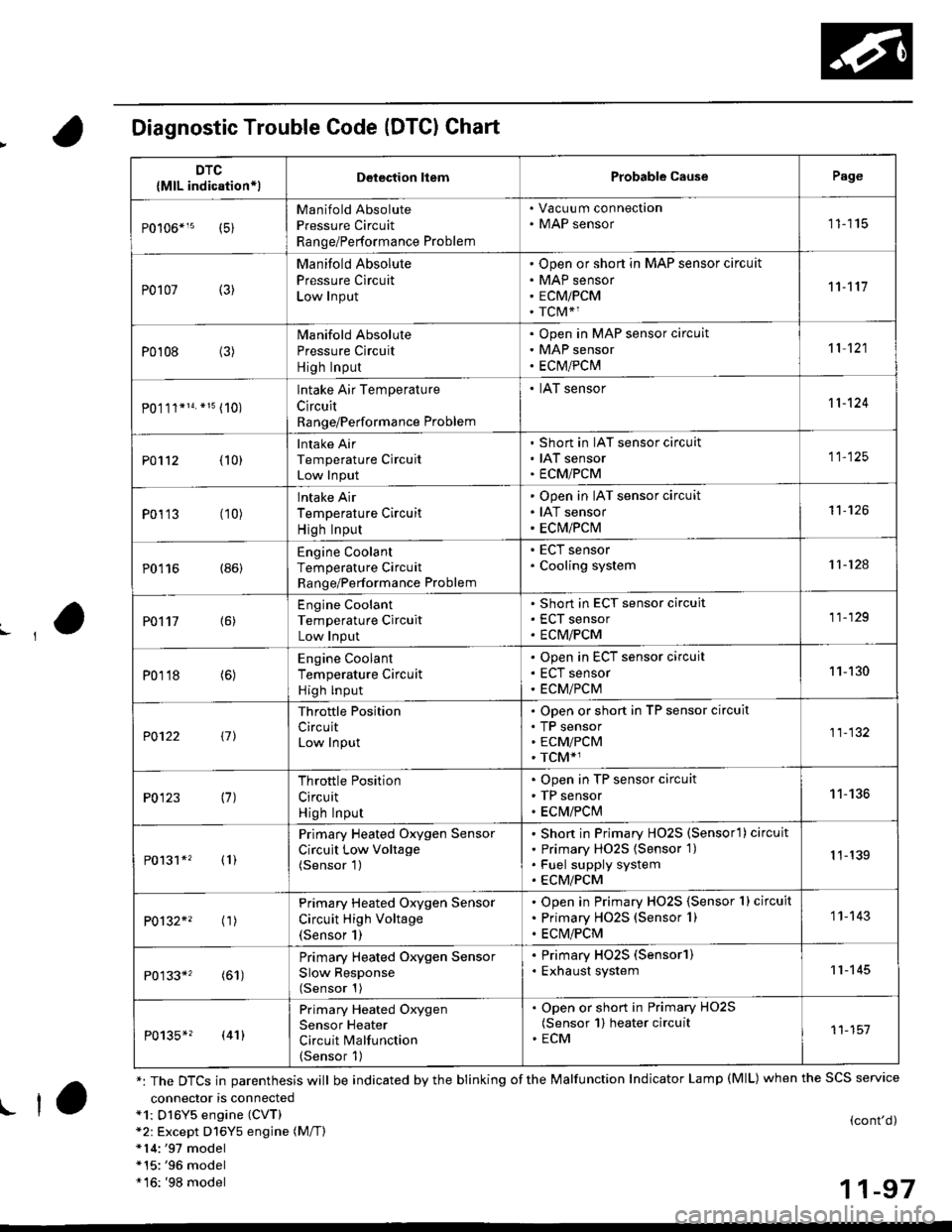
Diagnostic Trouble Code (DTCI Chart
connector is connecteda1: Dl6Y5 engine (CVT)*2: Except D16Y5 engine (M/T)*14:'97 model*15:'96 model*16: '98 model
(cont'd)
11-97
DTC
{MlL indication*lDelection liemProbable CausePage
Manifold Absolute
Pressure Circuit
Range/Performance Problem
. Vacuu m connection. MAP sensor11115
P0107 (3)
Manifold Absolute
Pressure Circuit
Low Input
Open or short in MAP sensor circuit
MAP sensor
ECMiPCM
TCM*1
11't1'l
P0108 (3)Manifold Absolute
Pressure Circuit
High Input
Open in MAP sensor circuit
MAP sensor
ECtvt/PCM
't 1 121
P0.111*14. *15 (10)
lntake Air Temperature
Circuit
Range/Performance Problem
. IAT sensor11-124
PO112 {10}
Intake Air
Temperature Circuit
Low Input
Short in IAT sensor circuit
IAT sensor
ECMiPCM
11-125
P0113 (10)lntake Air
Temperature Circuit
High Input
Open in IAT sensor circuit
IAT sensor
ECM/PCM
't1-126
P0116 (86)Engine Coolant
Temperature Circuit
Range/Performance Problem
. ECT sensor. Cooling system11-124
PO't't7 {6)
Engine Coolant
Temperature Circuit
Low Input
Short in ECT sensor circuit
ECT sensor
ECM/PCM
11-129
P0118 (6)Engine Coolant
Temperature Circuit
High lnput
Open in ECT sensor circuit
ECT sensor
ECM/PCM
11-130
?0122 t1l
Throttle Position
CircuitLow Input
Open or short in TP sensor circuit
TP sensorECM/PCM
TCM*1
11-132
P0123 (7)Throttle Position
Circuit
High Input
Open in TP sensor circuit
TP sensor
ECM/PClvl
11-136
P0131*' (1)
Primary Heated Oxygen Sensor
Circuit Low Voltage(Sensor 1)
Short in Primary HO2S (Sensorl ) circuit
Primary HO2S {Sensor 1)
Fuel supply system
ECM/PCM
1 1-139
P0132*' ('�r)
Primary Heated Oxygen Sensor
Circuit High Voltage(Sensor 1)
Open in Primary HO2S {Sensor 1} circuit
Primary HO2S (Sensor 1)
ECM/PCM
1 1- 143
P0133*' (61)
Primary Heated Oxygen Sensor
Slow Response(Sensor 1)
. Primary HO2S (Sensorl). Exhaust system11-145
P0135*? (41)
Primary Heated Oxygen
Sensor Heater
Circuit Malfunction(Sensor 1)
. Open or short in Primary HO2S(Sensor 1) heater circuit. ECM11-151
*: The DTCS in parenthesis will be indicated by the blinking of the Malfunction Indicator Lamp (MlL) when the SCS service
! ta
Page 367 of 2189
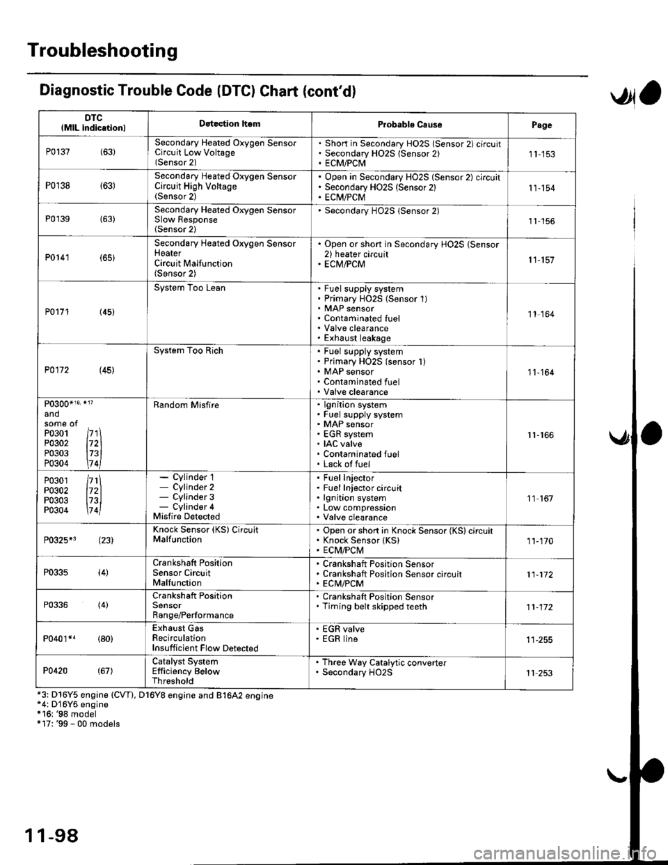
Troubleshooting
DTClMlL indicationlDatection hsmProbablo CausePage
P0137(63)Secondary Heated Oxygen SensorCircuit Low Voltage(Sensor 2)
Short in Secondary HO2S lSensor 2) circuitSecondary H02S {Sensor 2)ECM/PCI\41 1-153
P0r38 {63)Secondary Heated Oxygen SensorCircuit High Voltage(Sensor 2)
Open in Secondary HO2S (Sensor 2) circuitSecondary HO2S (Sensor 2)EC[I/PCM11-154
P0'139 (63)Secondary Heated Orygen SensorSlow Response(Sensor 2)
Secondary H02S lSensor 2)1l-156
P0141 (65)
Secondary Heated Oxygen SensorHeaterCircuit Malfunction(Sensor 2)
. Open or short in Secondary HO2S (Sensor2) heater circuit. ECM/PCM11-157
P0171 (45)
System Too LeanFuel supply systemPrimary HO2S (Sensor 1)MAP sensorContaminated fuelValve clearanceExhaust leakage
11,164
P0172 (45)
System Too RichFuel supply systemPrimary HO2S (sensor l)MAP sensorContaminated fuelValve clearance
11-164
P0300*16' }l?
andsome ofPo3o1 /r'' \P0302 l72lP0303 l73lP0304 \7 4l
Random Misfirelgnition systemFuel supply systemMAP sensorEGR systemIAC valveContaminated fuelLack of fuel
r1-r66
P0301P0302P0303P0304
/rt\172ll73l\7 4l
- Cylinder 1- Cylinder 2- Cylinder 3- Cylinder 4Misfire Detected
Fuel InjectorFuel Injector circuitlgnition systemLow compressionValve clearance
11 167
P0325*3 (23)Knock Sensor (KS) CircuitMalfunctionOpen or short in Knock Sensor (KS) circuitKnock Sensor {KS)ECM/FCtvl11-170
P0335(4)Crankshaft PositionSensor CircuitMalfunction
Crankshaft Position SensorCrankshaft Position Sensor circuitECM/PCM11-172
P0336(4)Crankshaft PositionSensorRange/Performance
. Crankshaft Position Sensor. Timing belt skipped teeth11-172
P040'�r*r (80)Exhaust GasRecirculationInsufficient Flow Detected
' EGR valve. EGR line
P0420(67)Catalyst SystemEfficiency BelowThreshold
. Th.ee Way Catalytic converter. Secondary HO2S11 253
Diagnostic Trouble Code (DTCI Chat (cont'dl
*3: D16Y5 engine (CVT), D16Y8 engine and B1642 engine*4: D'16Y5 engine*16: '98 model+17: '99 - 00 models
,Jla
1 1-98