speed HONDA CIVIC 1996 6.G Workshop Manual
[x] Cancel search | Manufacturer: HONDA, Model Year: 1996, Model line: CIVIC, Model: HONDA CIVIC 1996 6.GPages: 2189, PDF Size: 69.39 MB
Page 889 of 2189
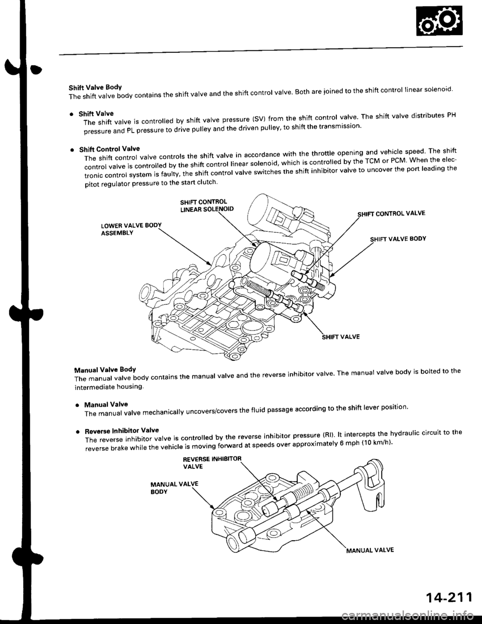
Shift Valve BodY
The shift valve body contains the shift valve and the shift control valve. Both are ioined to the shift control linear solenoro.
r tl'ft1il1rf"","" is controred by shift varve pressure (sV) from the shift contror varve. The shift varve distributes pH
pi""aur" "nO PL pressure to drive pulley and the driven pulley' to shift the transmission'
t t*"rilf:::lr';ivarve contrors the shift varve in accordance with the throttre opening and vehicle speed rhe shift
control valve is convorr"o uv ti" "iirt "ontrol linear solenoid, which is controlled by the TcM or PcM When the elec-
tronic control system is faulty, t;; snift controt uutue "witches the shift inhibitor valve to uncover the port leading the
pitot regulator pressure to the start clutch
CONTROL VALVE
VALVE BODY
T;J:"i"""1ff"t""ilody contains the manuar varve and the reverse inhibitor varve. The manuat varve bodv is borted to the
intermediate houslng
. ManualValve
The manual valve mechanicallY uncovers/covers the fluid passage according to the shift lever position'
'
ff:e;;;.'::'?Xftl::T",* is contro ed by the reverse inhibitor pressure (Rl). lt intercepts the hvdraulic circuit to the
reverse brake while the vehicle is moving forward at speeds over approximatelv 6 mph (10 km/h)'
REV€RSE INHIBITORVALVE
MANUAL VALVEBODY
SHIFT CONTROL
MANUAL VALVE
14-211
Page 893 of 2189
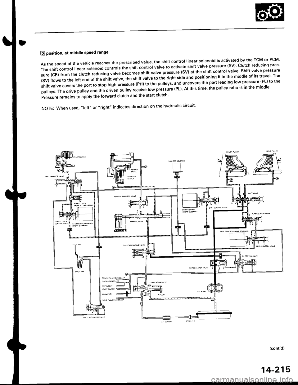
E position, at middle sPeed range
Asthespeedofthevehic|ereachestheprescribedVa|ue,theshiftcontro||inearsolenoidisactivatedbytheTcMorPcM'
Theshiftcontro||inearso|enorocontroIsttresniftcontroIVa|vetoactivateshiftVa|vepressure(SV)'c|utchreducingpres-
sure (CR) trom the clutch reduclng valve becomes shift valve pressure (SV) at the shift control valve Shift valve pressure
(SV)flowstothe|eft"noottr'"st'ittu"tue.theshiftVa|Vetotherightsideandpositioningitinthemidd|eofitstrave|.The
shift valve covers th" pon ao ",oo nLior".irr" tiHl a ,tr" pulleys, and uncovers the port leading low pressure (PL) to the
pu eys. The drive pu ey and tne oriJen priLy |."""iu" to* pressure (PL). At this time, the pulley ratio is in the middle'
Pressure remains to apply the forward clutch and the start clutch'
NOTE: When used, "|eft" or "right" indicates direction on the hydraulic circuit'
(cont'd)
14-215
Page 894 of 2189
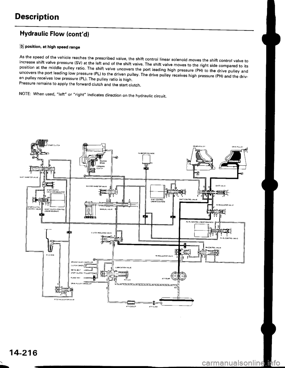
Description
Hydraulic Flow (cont'd)
@ position, at high spe6d range
As the speed of the vehicle reaches the prescribed value, the shift control linear sol€noid moves the shift contror vatve toincrease shift valve pressure (SV) at the left end of the shift valve. ttre srrit vatve moves to the right side compared to itsposition at the middle pulley ratio. The shift valve uncovers the port leading high pressure (pxito ttre d.ve puley anduncovers the port leading low pressure (PL) to the driven pulley. The drive pu|ey receives high pressure (pH) and the driv-en pulley receives low pressure (pL). The pulley ratio is high.Pressure remains to apply the forward clutch and the start clutch,
NOTE: When used, "left,, or,,right" indicates direction on the hydraulic circuit.
L
14-216
Page 896 of 2189
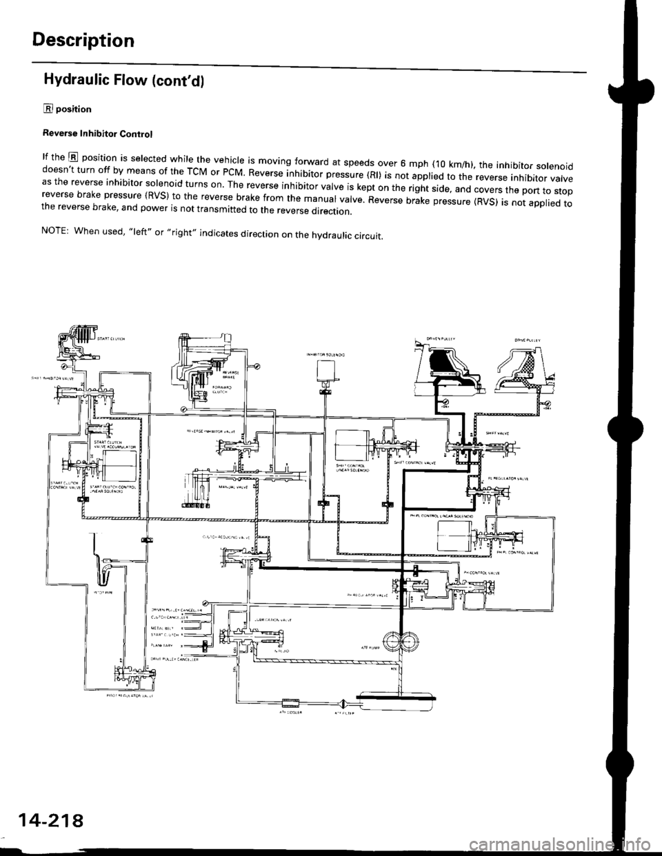
Description
Hydraulic Flow (cont'dl
E position
Reverse Inhibitor Conirol
lf the E position is selected while the veiicle is moving forward at speeds over 6 mph (10 km/h), the inhibitor solenoiddoesn't turn off by means of the TcM or PCM Reverse inhibitor pressure (Rl) is not applied to the reverse inhibitor valveas the reverse inhibitor solenoid turns on. The reverse inhibitor valve is kept on the right side, and covers the pon ro sropreverse brake pressure {RVS} to the reverse brake from the manual valve. Reverse brike pressure (RVs) i; not appried tothe reverse brake, and power is not transmitted to the reverse direction.
NOTE: When used, "left,' or,,right,, indicates direction on the hydraulic circuit.
14-218
Page 901 of 2189
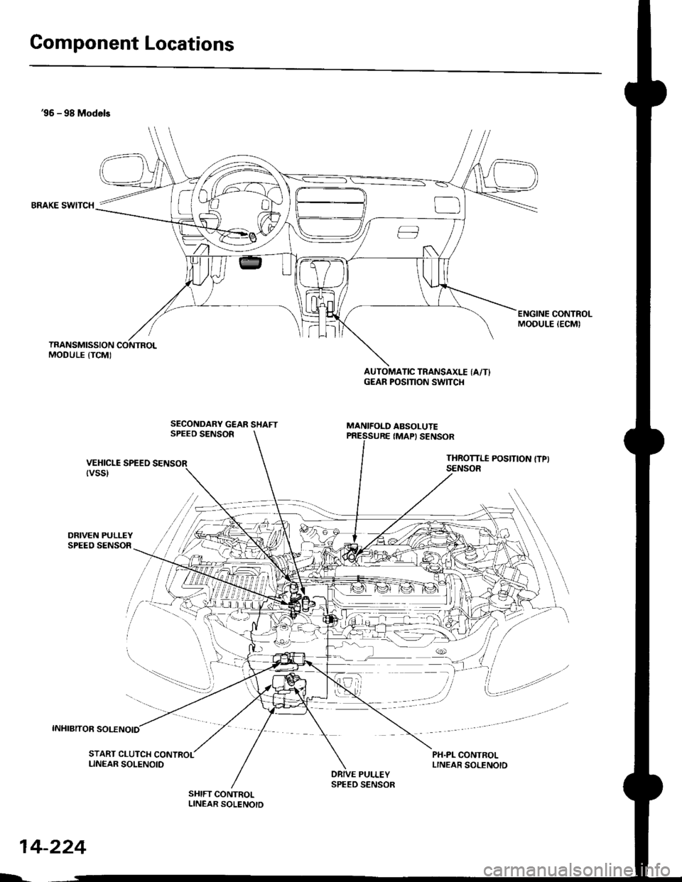
Component Locations
36 - 98 Models
BRAKE SWITCH
DRIVEN PULLEYSPEED SENSOR
INHIBITOR SOLENOID
ENGINE CONTROLMODULE IECMI
SECONDARY GEAR SHAFTSPEEO SENSOR
AUTOMATIC TRANSAXLE (A/T}GEAR POSITION SWITCI{
MANIFOLD ABSOLUTE
VEHICLE SPEEO SENSOR{vss}
IMAPI SENSOR
THROTTI.I POSITION {TPISENSOR
PH.PL CONTROLLINEAR SOLENOID
/i/ i,' / ,','4
,i/:1
t"--.---.- i,,
-_,-:-_a.--:
il
START CLUTCH CONTROLLINEAR SOLENOIDPULLEY
SHIFT CONTROLLINEAR SOLENOTD
$r,
14-224
h
SPEED SENSOR
Page 902 of 2189
![HONDA CIVIC 1996 6.G Workshop Manual 99 - 00 Models
CONTROL
AUTOMATIC TRANSAXLE IA/TI
GEAR POS]TION SW]TCH
MANIFOLD ABSOLUTESECONDANY GEAR SHAFT
SPEED SENSORIMAPI SENSOR
VEHICLE SPEED SENSOR
tvss)
THROTTLE POS]TION ITP)SENSOR
PH.PL CONT HONDA CIVIC 1996 6.G Workshop Manual 99 - 00 Models
CONTROL
AUTOMATIC TRANSAXLE IA/TI
GEAR POS]TION SW]TCH
MANIFOLD ABSOLUTESECONDANY GEAR SHAFT
SPEED SENSORIMAPI SENSOR
VEHICLE SPEED SENSOR
tvss)
THROTTLE POS]TION ITP)SENSOR
PH.PL CONT](/img/13/6068/w960_6068-901.png)
'99 - 00 Models
CONTROL
AUTOMATIC TRANSAXLE IA/TI
GEAR POS]TION SW]TCH
MANIFOLD ABSOLUTESECONDANY GEAR SHAFT
SPEED SENSORIMAPI SENSOR
VEHICLE SPEED SENSOR
tvss)
THROTTLE POS]TION ITP)SENSOR
PH.PL CONTBOLLINEAB SOLENOIO
DNVEN PUL]-EY
SPEED SENSOR
START CLUTCH CONTROL
PULLEY
SHIFT CONTROLLINEAR SOLENOIO
LINEAR SOIENOID
SPEED SENSOR
14-225
Page 905 of 2189
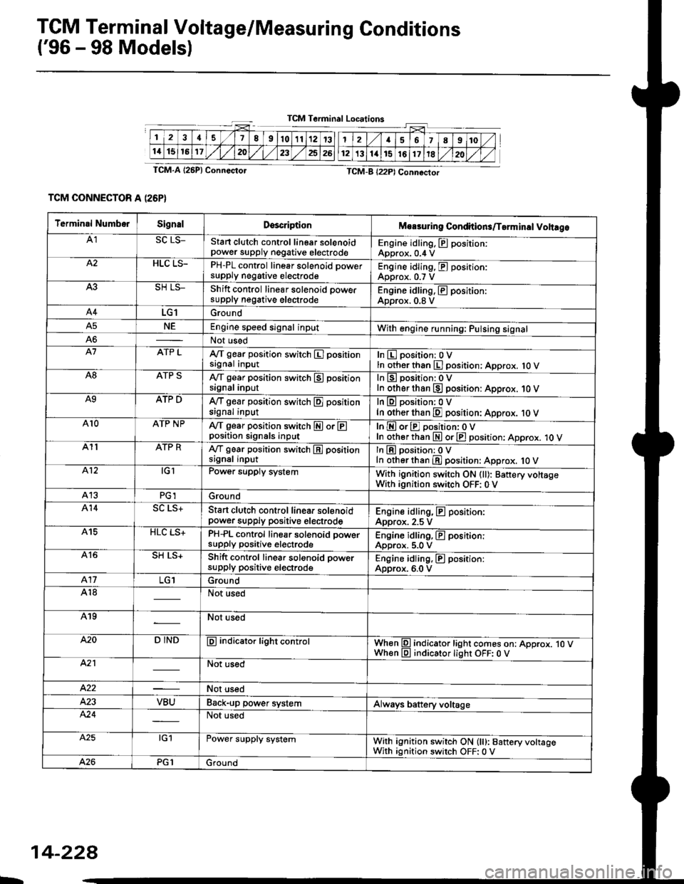
TCM Terminal Voltage/Measuring Gonditions
('96 - 98 Modelsl
TCM Terminal Loc.tions
TCM-A l25P) Connecto.
TCM CONNECTOR A (26P}
TCM-B (22P) Connectot
2418910111213
1115161720232526
Terminal NumbetSignalDsscriptionMoasuring Conditions/Torminsl Vohrgo
A1SC LS_Stan clutch control linear solenoidpower supply negative electrodeEngine idling, E position:Approx. 0.4 VHLC LS-PH-PL control linear solenoid Dowersupply negative electrodeEngine idling, E position:Approx. 0.7 V
Shift control linear solenoid oowersupply negative electrodeEngine idling, E position:Approx. 0.8 V
A4LG1Ground
NEEngine speed signal inputWith engine running: Pulsing signalA6Not used
A7ATP LA/f gear position switch El positionsignal inputInEposition:OVIn other than El position: Approx. 1O VA8ATP Sly'T gear position switch E positionsignal inputIn lg position: 0 VIn other than E position: Approx. 10 VA9ATP DA{/T gear position switch E positionsignal inputIn lll position: 0 VIn other than E position: Approx. 10 VAr0ATP NPA,/T gear position switch E or Eposition signals inputInEorEposition:oVIn otherthan E orE position: Approx. 1O VA11ATP RA,/T gear position switch E positionsignal inputIn lE position: 0 VIn other than E position: Approx. 1O VA.12tGlPower supply systemWith ignition switch ON (ll): Banery voltsgeWith ignition switch OFF: 0 VA13PG1Ground
414Start clutch control linea. solenoidpower supply positive electrodeEngine idling, E position:Approx. 2.5 VA15HLC LS+PH-PL control line8|. solenoid powersupply positive electrodeEngine idling, El position:Approx. 5.0 VA16SH LS+Shift control linear solonoid oowersupply positive electrodeEngine idling, E position:Approx. 6.0 V417Ground
A18Not used
A19Not used
420D INDE indicator light controlWhen l9l indicator light comes on: Approx. jO VWhen lll indicator lighr OFF: 0 VA2'lNot used
422Not used
VBUBack-up power systemAlways battery voltage424Not used
A.25tG1Power supply systemWith ignition switch ON (lt): Baftery voltageWith ignition switch OFF:0 VPG1Ground
L
14-228
Page 906 of 2189
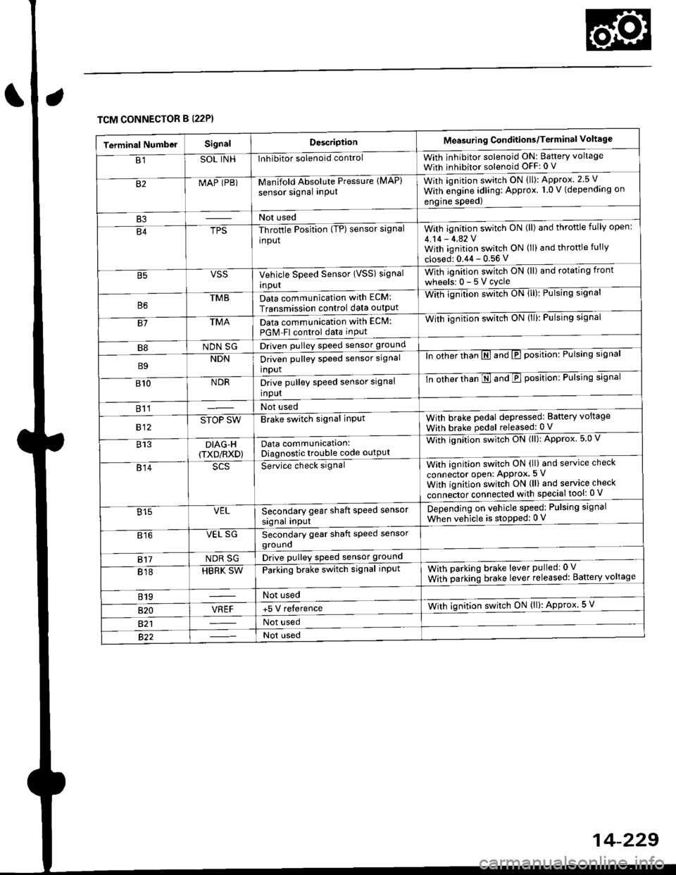
TCM CONNECTOR B (22P}
Terminal NumbelSignalDescriptionMeasuring Conditions/Terminal Voltage
B1SOL INHInhibitor solenoid controlWith inhibitor solenoid ON: Baftery voltage
With inhibitor solenoid OFF: 0 V
82MAP (PB)-M an if old Absol r-rte Pressure IMAP)
sensor signal inPUtWith iqnition switch ON (ll): Approx.2.5 V
With e;gine adling: Approx. 1.0 V (depending on
engine speed)
B3Not used
B4TPS-Throttle Position (TP) sensor signal
input
With ignition switch ON (ll) and throftle fully open:
4.14 - 4.42 VWith ignition switch ON (ll) and throttle fully
closed: 0.44 - 0.56 V
VSSVehicle Speed Sensor (VSS) signal
Inpur
With ignition switch ON (ll) and rotating front
wheelsr 0-5Vcycle
TMBData communication with ECM:
Transmission control data outpUt
With ignilion swltch UN lll): rulslng slgnar
81TMAData communication with EClvl:
PGM Fl control data inPut
With ignition swltch uN {ll,: l-ulslng slgnal
B8NDN SGDriven pulley speed sensor ground
B9NDNDriven pulley speed sensor signal
input
ln other thTnE and E position: Pulsing signal
810NDRDrive pulley speed sensor signal
Input
-tn ottrer ttran E ana E position: Pulsing signal
811Not used
812STOP SWBrake switch signal inPutWith brake pedal depressed: Battery voltage
With brake pedal released: 0 V
813DIAG-H(TXD/RXD)Data communication:Diagnostic trouble code outPut
Wittr ignitio.r s*itct' ON (ll): Approx 5.0 V
814Se-ice ctrect signatWith ignition switch ON (ll) and service check
connector oPen: APProx.5 V
With iqnition switch ON (ll) and service check
"onn"itot. connect"d with special tool: 0 V
Secondary gear shaft speed sensor
signal input
Depending on vehicle speed: Pulsing signal
When vehicle is stoPped: 0 V815VEL
816VEL SGSecondary gear shaft speed sensorgrouno
817NDR SGDrive pulley speed sensor ground
818HBRK SWParking brake switch signal inPutWith parking brake lever pulledr 0 V
With parking brake lever released: Battery voltage
819Not used
B�20VREF+5 V relerenceWith ignition switch ON (ll): Approx 5 V
821Not used
Not used
Page 908 of 2189
EI€INECOOLTI'IITEUPEFATUFESENSOF
SPEEDSEllsoF
Y
I
I
IGFN8U
J-
HI NHIEITORI soLEr,roro
I:
llll
EE
*fl&'u''!l^" iflfl.S$'soLEl€|0
TI
.-l-ttttI u00u I
ilillfSIft,'
14-231
Page 910 of 2189
![HONDA CIVIC 1996 6.G Workshop Manual \a
PCM CONNECTOR D {16P)
14-233
Terminal Numbs]SignalDescriptionMeasuring Conditions/Terminal Voltage
D1VELSecondary gear shaft speed
sensor signal input
Depending on vehicle speed: Pulsing signal
Whe HONDA CIVIC 1996 6.G Workshop Manual \a
PCM CONNECTOR D {16P)
14-233
Terminal Numbs]SignalDescriptionMeasuring Conditions/Terminal Voltage
D1VELSecondary gear shaft speed
sensor signal input
Depending on vehicle speed: Pulsing signal
Whe](/img/13/6068/w960_6068-909.png)
\a
PCM CONNECTOR D {16P)
14-233
Terminal Numbs]SignalDescriptionMeasuring Conditions/Terminal Voltage
D1VELSecondary gear shaft speed
sensor signal input
Depending on vehicle speed: Pulsing signal
When vehicle is stoPPed: APProx. 0 V
02SOL INHlnhibitor solenoid controlWith inhibitor solenoid ON: Battery voltage
With inhibitor solenoid OFF: 0 V
D3SH LSMShift control linear solenoid
power supply negative electrode
D4SH LSPShift control linear solenoid
power supply positive electrode
With ignition switch ON (ll): Pulsing signal
D5VB SOLPower supply for solenoid valvesWith ignition switch ON (ll): Baftery voltage
With ignition switch OFF:0 V
D6ATP RA,/T gear position switch E
position input
InEposition:0V
In other than B position; Approx. 10 V
D]VEL SGSecondary gear shaft sPeed
sensor ground
D8Not used
D9Not used
D10NDNDriven pulley speed sensor signal
anput
In other than E and E position: Pulsing signal
D11NDRDriven pulley speed sensor signal
input
ln other than E and E position: Pulsing signal
D12NDR SGDrive pulley speed sensor ground
D13ATP SA,/T gear position switch E
position input
InE position: 0V
In other than E position: Battery voltage
D14D INDD indicator light controlWhen ignition switch is first turned ON (ll):
Battery voltage for two seconds
In E position: Battery voltage
D15Not used
D16NDN SGDriven pulley speed sensor
grou nd