speed HONDA CIVIC 1996 6.G Workshop Manual
[x] Cancel search | Manufacturer: HONDA, Model Year: 1996, Model line: CIVIC, Model: HONDA CIVIC 1996 6.GPages: 2189, PDF Size: 69.39 MB
Page 717 of 2189
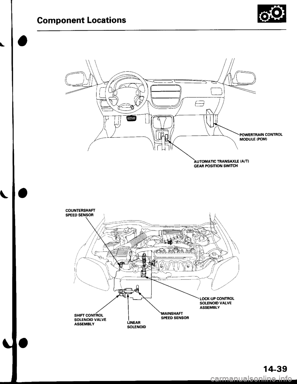
Component Locations
POWERTRAIN CONTROLMODULE (PCM)
TRANSAXLE {A/TI
COUNI€RSHAFTSPEED SENSOR
SOI,TNOID VALVEASSEMBLY
SOLENOID VALVEASSEMBLY
GEAR POSITION SWITCH
SPEED SENSOR
1+39
Page 719 of 2189
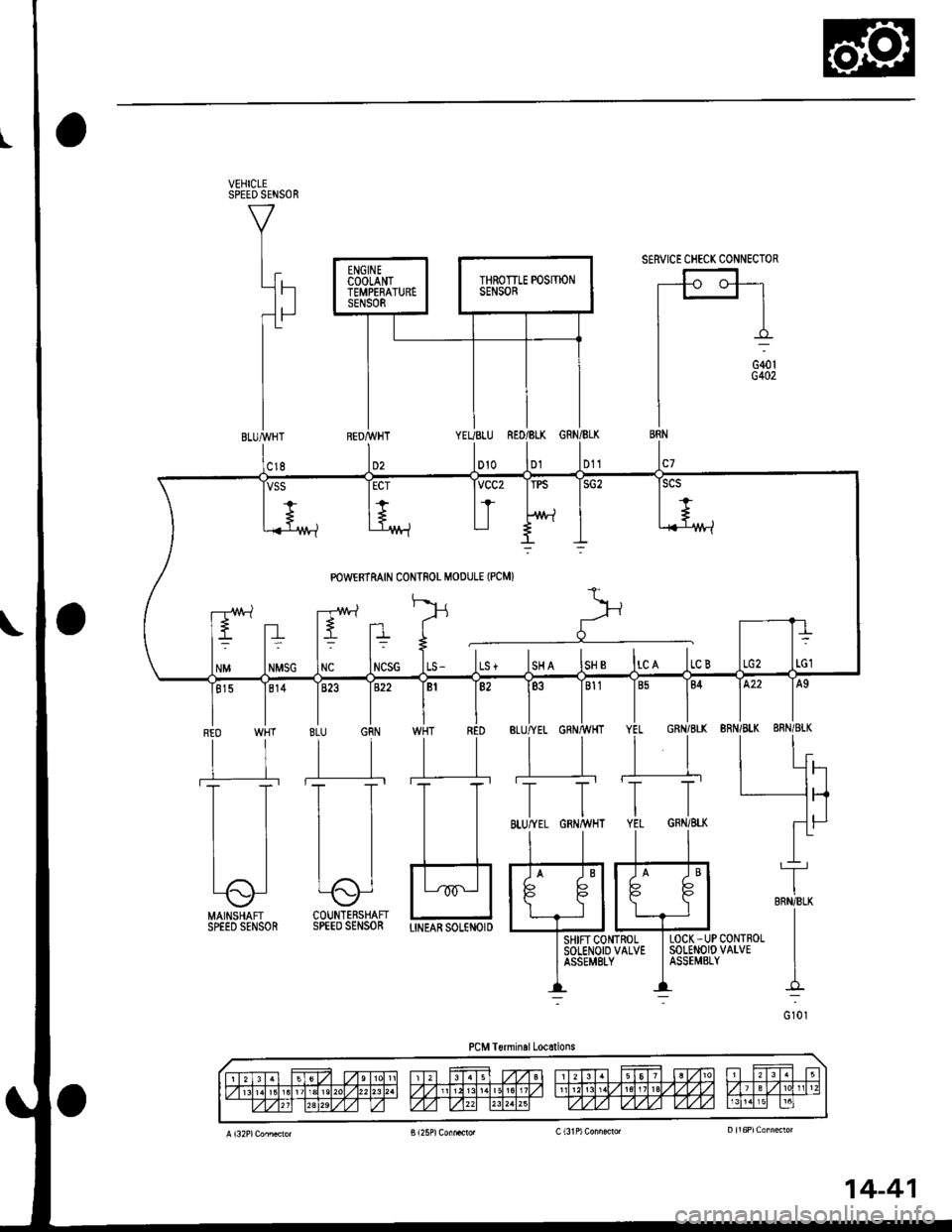
SERVICE CHECK CONNECTOR
LOCK -UP CONTROLSOLENOIO VALVEASSEMELY
RED WHT
tlll'
IT
tl
ll
Lo-l
MAINSHAFTSPEED SENSOR
TBRNiBLK
I
I
I-
G 101
NCSG ILS - ILS + ISH A ISH B ltc A ltc B
SHIF'CONTROLSOTENOID VALVEASSEMEI-Y
PCM Terminel Locations
14-41
Page 721 of 2189
I
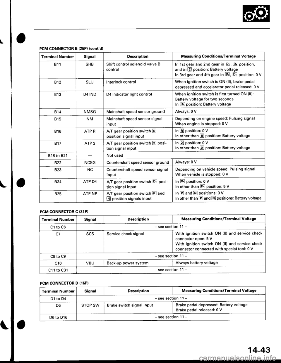
PCM CONNECTOR B {25P1 {cont'dl
Terminal NumberSignalDescriptionMeasuring Conditions/Terminal Vohage
811SHBShift control solenoid valve B
control
In 1st gear and 2nd gear in -q1, q11 position,
and in E] position: Battery voltage
In 3rd gear and 4th gear in lD.J, [Dr- position: 0 V
B't2SLUInterlock controlWhen ignition switch is ON (ll), brake pedal
deoressed and accelerator Dedal released: 0 V
813D4 INDD4 Indicator light controlWhen ignition switch is first turned ON (ll):
Battery voltage for two seconds
In E position: Baftery voltage
B't 4NMSGMainshaft speed sensor groundAlways: 0 V
E tcNMMainshaft speed sensor signal
input
Depending on engine speed: Pulsing signal
When engine is stopped: 0 V
816ATP RAy'T gear position switch Eposition signal input
InE position: 0V
In other than E position: Battery voltage
817ATP 2A/T gear position switch E posi-
tion signal input
InE position: 0V
In orher than E position: Battery voltage
818 to 821Not used
s22NCSGCountershatt speed sensor groundAlwaysr 0 V
B�23NCCountershaft speed sensor signal
input
Depending on vehicle speed: Pulsing signal
When vehicle is stopped: 0 V
B�24ATP D4Ay'T gear position switch lor posi-
tion signal input
InEposition:0V
In other than 6 position: 5 V
ATP NPA,/T gear position switch E and
N position signals input
InE and E positions: 0V
In otherthan E and N] positions: Battery voltage
PCM CONNECTOR C {31P)
Terminal NumberSignalDescriptionMeasuring Conditions/Terminal Voltage
Cl to C6- see section 11 -
c1Service check signalWith ignition switch ON (ll) and service check
connector oDen; 5 V
With ignition switch ON (ll) and service check
connector connected with sDecial tool: 0 V
C8 to Cg- see section 11 -
c10VBUBack-up power systemAlways battery voltage
C11 to C31- see section '11 -
PCM CONNECTOR D (16P}
Terminal NumberSignalDescriptionMeasuring Conditions/Terminal Voltage
Dl to D4- see section 11 -
D5STOP SWBrake switch signal inputBrake pedal depressed: Battery voltage
Brake pedal released: 0 V
D6 to D16- see section 1 l -
14-43
Page 725 of 2189
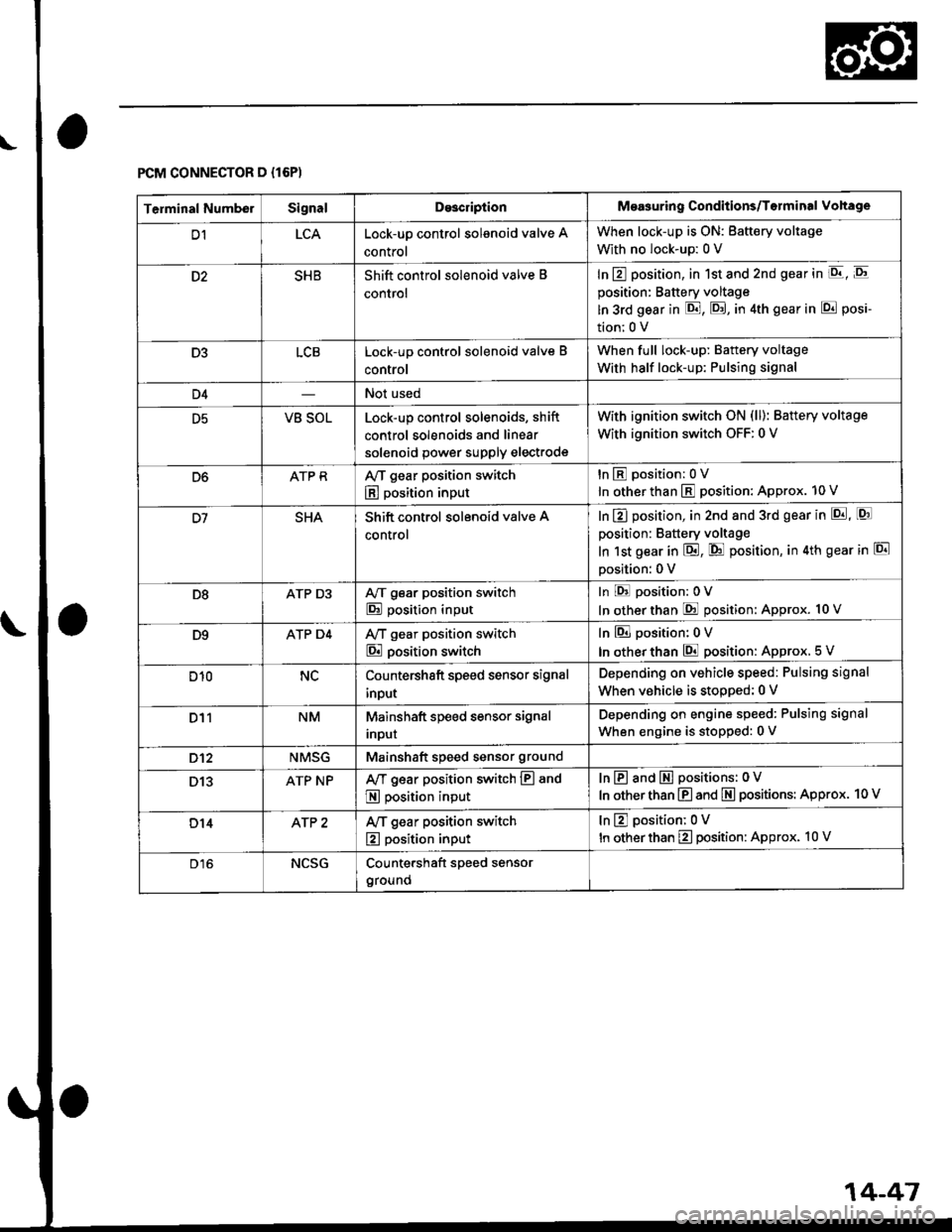
FCM CONNECTOR D {16P)
\o
14-47
Terminal NumberSignalDo3criptionMeasuring Conditions/Torminal Vohage
D1LCALock-up control solenoid valve A
control
When lock-up is ON: Battery voltage
With no lock-up: 0 V
SHBShift control solenoid valve B
control
In E position, in 1st and 2nd gear in E, E
position: Battery voltage
ln 3rd gear in E, E, in 4th gear in E posi-
tion;0 V
D3LCBLock-up control solenoid valve B
control
When full lock-up: Battery voltage
With half lock-up: Pulsing signal
D4Not used
D5VB SOLLock-up control solenoids, shift
control solenoids and linear
solenoid power supply electrode
with ignition switch oN (ll): Battery voltage
With ignition switch OFF: 0 V
D6ATP RAy'T gear position switch
E position input
tnEposition:0V
In other than E position: Approx. 10 V
SHAShift control solenoid valve A
control
In E] position, in 2nd and 3rd gear in p!, [Q]
position: Battery voltage
In 1st gear in E, @ position, in 4th gear in El
Dosition: 0 V
D8ATP D3A/T gear position switch
E position input
In E position:0V
In otherthan @ position: Approx. 10 V
D9ATP D4Ay'T gear position switch
E position switch
In El position: 0 V
In other than E position: Approx. 5 V
D10NCCountershaft speed sensor signal
input
Depending on vehicle speed: Pulsing signal
When vehicle is stooped: 0 V
D11NMMainshaft speed sensor signal
Inpur
Depending on engine speed: Pulsing signal
When engine is stopped: 0 V
D't2NMSGMainshaft speed sensor ground
D13ATP NPAy'T gear position switch E and
E position input
InE and E positions: 0V
In other than E and E positions: Approx. 10 V
D14AfP 2Ay'T gear position switch
E position input
tnEposition;0V
In other than E position: Approx. 10 V
D16NCSGCountershaft speed sensor
ground
Page 726 of 2189
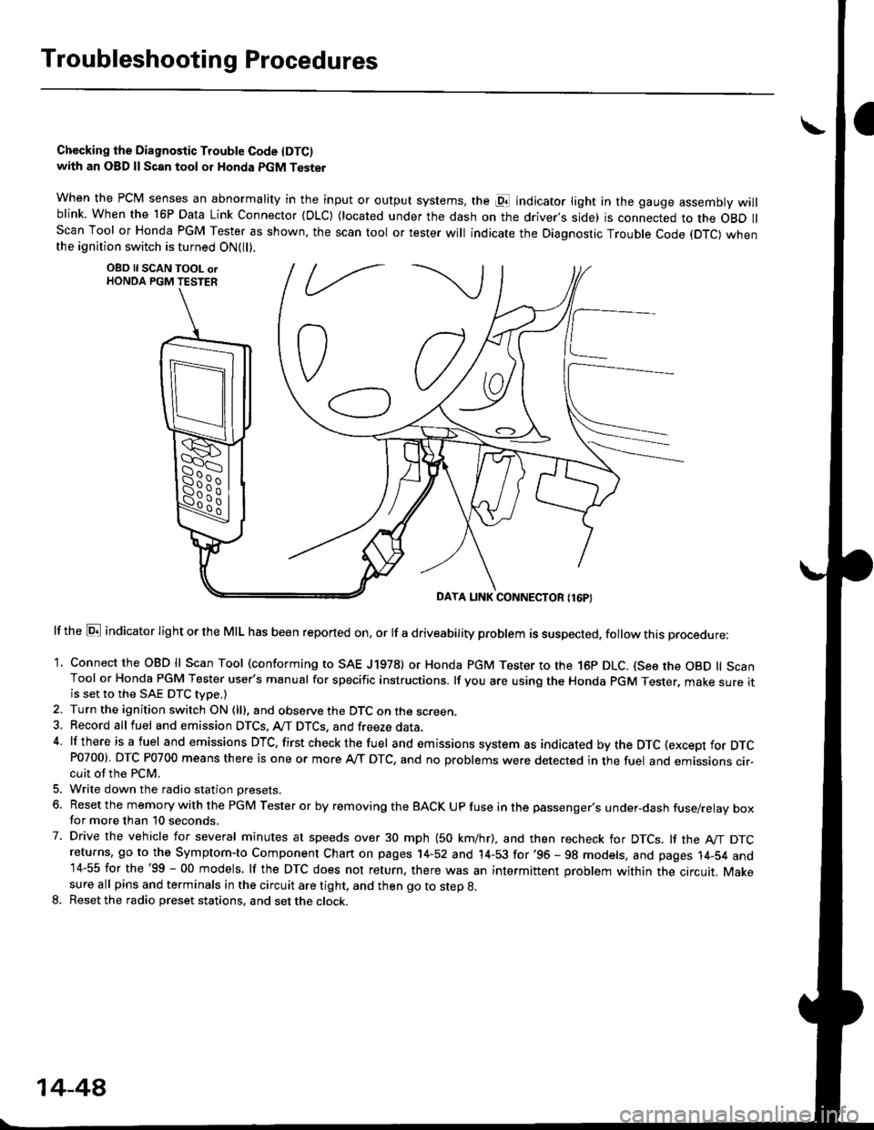
Troubleshootin g Procedures
Chccking the Diagnostic Trouble Code IDTC)with an OBD ll Scan tool or Honda PGM Tester
when the PCM senses an abnormality in the input or output systems, the pl indicator light in the gauge assembly willblink. When the 16P Data Link Connector (DLC) (located under the dash on the driver,s side) is connected to the OBD llScan Tool or Honda PGM Tester as shown, the scan tool or tester will indicate the Diagnostic Trouble Code (DTC) whenthe ignition switch is turned ON{ll).
lf the El indicator light or the MIL has been reported on, or lf a driveability problem is suspected, follow this procedure:
1. Connect the OBD ll Scan Tool (conforming to SAE J19781 or Honda PGM Tester to rhe 16p DLC. (See the OBD ll ScanTool or Honda PGM Tester user's manual for specific instructions. lf you are using the Honda PGM Tester, make sure itis set to the SAE DTC type.)
2. Turn the ignition switch ON (lll, and observe the DTC on the screen,3, Record all fuel and emission DTCS, A/T DTCS, and freeze data.4 lf there is a fuel and emissions DTC, first checkthe fuel and emissions system as indicated bythe DTC (except for DTCP0700). DTC P0700 means there is one or more A,/T DTC, and no problems were detected in the fuel and emissions cir-cuit of the PCM.
5. Write down the radio station oresets.
6. Reset the memory with the PGM Tester or by removing the BACK UP fuse in the passenger's under-dash fuse/relay boxfor more than 10 seconds.
7. Drive the vehicle for several minutes at speeds over 30 mph (50 km/hr), and then recheck for DTCS. lf the A"/T DTCreturns, go to the Symptom-to Component Chart on pages 14-52 and 14-53 for'96 - 98 models, and pages 14-54 and14-55 for the'99 - 00 models, lf the DTC does not return, there was an intermittent problem within the circuit. Makesure all pins and terminals in the circuit are tight, and then go to step g.
8. Reset the radio preset stations, and set the clock.
OBD ll SCAN TOOL orHONDA PGM TESTER
DAYA LINK CONNECTOR {16P}
14-44
Page 729 of 2189
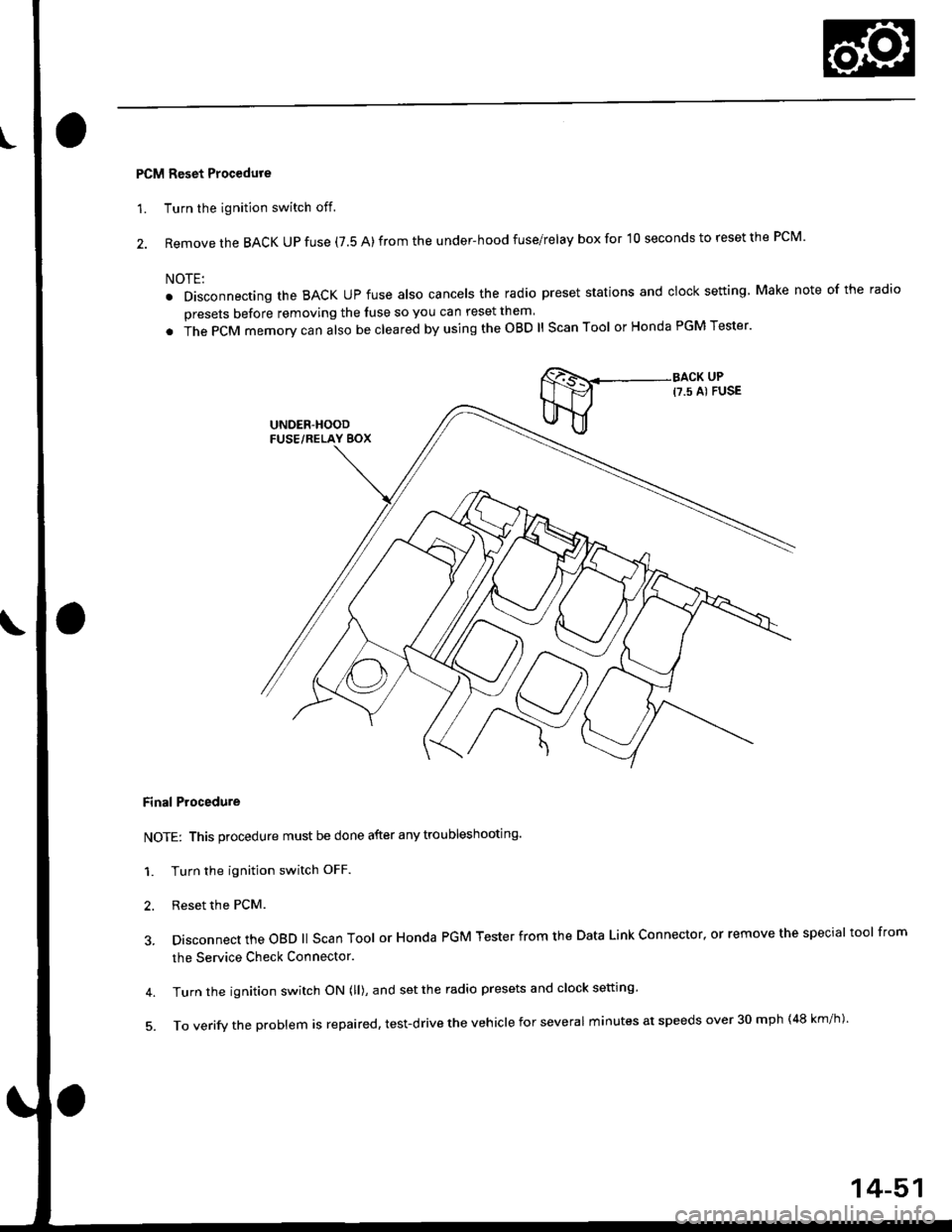
PCM Reset Procedure
1. Turn the ignition switch off.
2. Remove the BACK UP fuse (7.5 A) from the under-hood fuse/relay box for '10 seconds to reset the PCM'
NOTE:
. Disconnecting the BACK UP fuse also cancels the radio preset stations and clock setting Make note of the radio
presets before removing the luse so you can reset them
. in" gCfU memory can also be cleared by using the OBD ll Scan Tool or Honda PGM Tester'
Final Procedure
NOTE: This procedure must be done after any troubleshooting.
1. Turn the ignition switch OFF.
2. Reset the PcM.
3. Disconnect the oBD ll scan Tool or Honda PGM Tester from the Data Link connector, or remove the special tool from
the Service Check Connector.
4. Turn the ignition switch ON (ll), and set the radio presets and clock setting'
5'ToVerifytheprob|emisrepaired,test.drivetheVehic|eforseveralminutesatspeedsover30mph(48km/h).
14-51
Page 730 of 2189
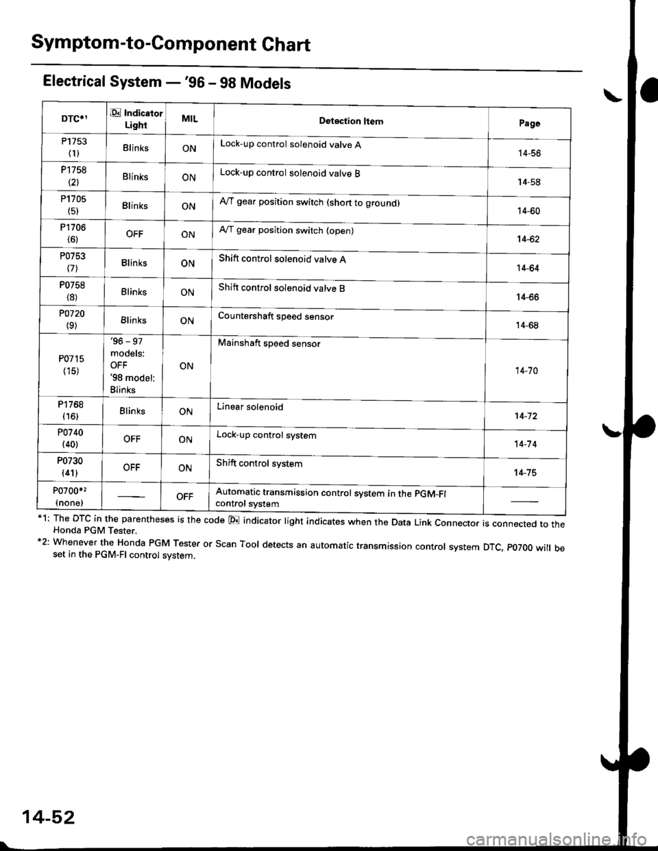
Symptom-to-Component Ghart
Electrical System -'gG - 98 Models
*1: The DTC in the parentheses is the code E indicator light indicates when the Data Link connector is connected to theHonda PGM Tester.*2: Whenever the Honda PGM Tester or Scan Tool detects an automatic transmission control system DTC, p07OO will beset in the PGM-FI control svstem.
DTCIIE Indicaior
LightMILDotection ltemPage
P1753
fl)BlinksONLock-up control solenoid valve A14-56
P1758
\21BlinksONLock-up control solenoid valve B14-58
P1705
(51BlinksONAy'T gear position switch (short to groundl14-60
P1706
(6)OFFONA,/T gear position switch (open)14-62
P0753
l7lBlinksONShift control solenoid valve A14-64
P0758
{8)ElinksONShift control solenoid valve B14-66
POl20
(9)BlinksONCountershaft speed sensor14-68
P0715
{15)
'96 - 97
models:
OFF'98 model:
Blinks
ON
Mainshaft speed sensor
14-70
P1768
{16)BlinksONLinear solenoid't 4-72
P0740
(40)OFFONLock-up control system14-7 4
P0730
(41)OFFONShift control system14-75
P0700*,
(none)Automatic transmission control svstem in the pGM-Fl
control svstem
14-52
Page 732 of 2189
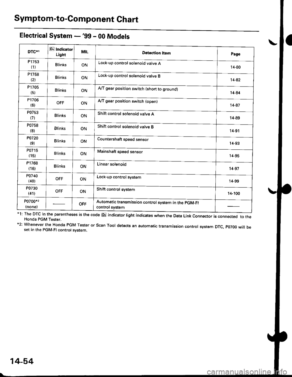
Symptom-to-Component Chart
Electrical System -'99 - 00 Models
*1: The DTc in the parentheses is the code E indicator tight indicates when the Data Link connector is connected to theHonda PGM Tester.*2: Whenever the Honda PGM Tester or scan Tool detects an automatic transmission control system DTc, p07oo will beset in the PGM-FI control svstem
DTC*IE Indicator
LightMILDotostion ltemPage
P1753
fi)BlinksONLock-up control solenoid valve A'14-80
P1758
t2lBlinksONLock-up control solenoid valve B14-82
P1705
{5}BlinksONAy'T gear position switch {short to ground)14-84
P1706
(6)OFFONy'VT gear position switch {open)14-81
P0753
\71BlinksONShift control solenoid valve A14-89
P0758
(8)BlinksONShift control solenoid valve B14-9r
P0720
(9)BlinksONCountershaft speed sensorr4-93
P0715
(15)B linksONMainshaft speed sensor14-95
P1768
(16)BlinksONLinear solenoid't 4-97
PO7 40(40)OFFONLock-up control system14-99
P0730
(41)OFFONShift control svstem14- 100
P0700*,
(none)OFFAutomatic transmission control system in the pGM_Fl
controt svstem
14-54
Page 746 of 2189
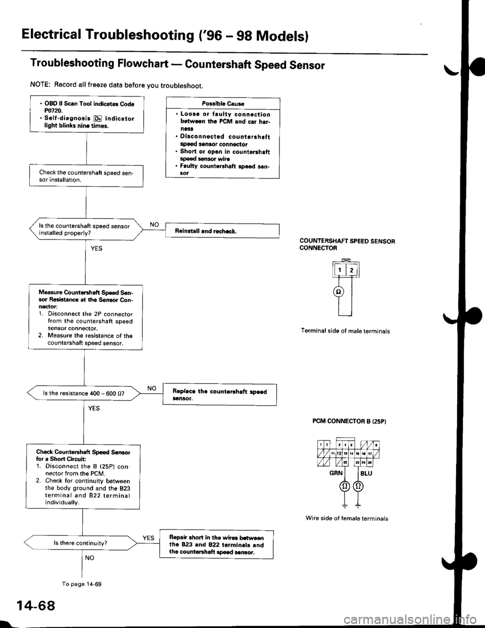
Electrical Troubleshooting ('gO - 98 Modelsl
Troubleshooting Flowchart - Countershaft Speed Sensor
Po$iblo Causa
' Loosg or laulty conncctionbotwocn tho PCM and c.i hrr-n1't!' Disconnoctad countorahottlpo€{ san3or oonnoctot. Short or opon in countorshaftspeed lonsor wire. F ulty counte.lhalt spe6d s6n-sol
COUNTERSHAFT SPEED SENSORCONNECTOR
lFI,]1-F=r
9l
L_l
Terminal side ol male terminals
PCM CONNECTOR B I25P}
1
l'
NOTE; Record allfreeze data before you troubleshoot.
. OBO ll Scln Tool indicat6 Codem7z).. S6lt-dirgnosis E indic.tollight blink! nin. tim6,
ls the countershaft spoed sensorinstalled properly?
Moa3ure CountoEhaft Sp€ed S6n-sor Reaktanc€ at tho Son3or Con-noctor1. Disconnect the 2P connectortrom the countershaft spgedsensor connector,2. Measure the resistance of thecountershaft sDeed sensor,
ls the resistance 400 - 600 0?
Chock Countersh.ft Spood Scr|3olfor a Shoft Circuit:1. Disconnect the B {25P) connector from the PCM.2. Check for continuity betweenthe body ground and the 823terminal and 822 terminalindividually.
Repai. .hort in th. wiroa b.t$re€ntho 823 lnd 822 torminals .ndlho counteBhaft lpocd aenro..
To page 14-69
4-68
Wire side of temale terminals
Page 747 of 2189
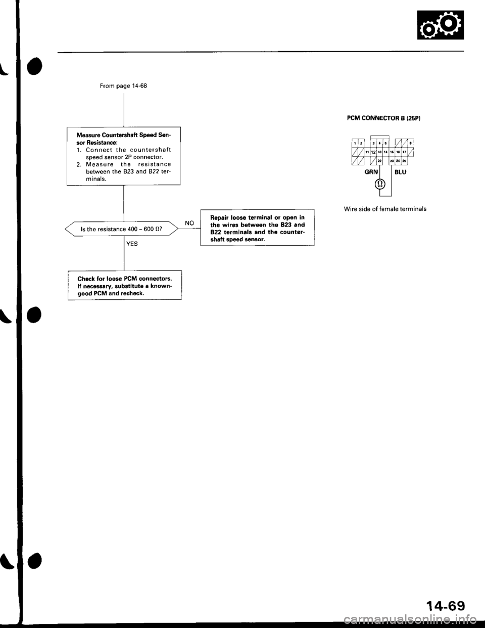
Measure CounteFhaft Sp€€d S6n-
sor Resistance:1. Connect the countershaftspeed sensor 2P connector,2, Measure the resistancebetween the B�23 and 822 telmtnals.
Repair looso terminal ol opon inthe wiro3 between th6 823 and822 terminal3 and the counter-shaft soeed aen3or.
ls the resistance 400 - 600 0?
Check tor loosc rcM connestors.ll nocessary, sub3titute a known-good PCM and recheck.
PCM CONNECTOR 8 I25PI
Wire side oI female terminals
14-69