angle HONDA CIVIC 1996 6.G User Guide
[x] Cancel search | Manufacturer: HONDA, Model Year: 1996, Model line: CIVIC, Model: HONDA CIVIC 1996 6.GPages: 2189, PDF Size: 69.39 MB
Page 1125 of 2189
)
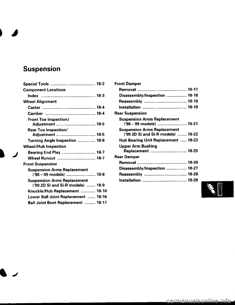
Suspension
Special Tools ............. 18-2
Component Locations
lndex ,,.............. ...... f8-3
Wheel Alignment
Caster .............. ....... 18-4
Camber .................. l8-4
Front Toe Inspection/
Adiustment ........ 18-5
Rear Toe lnspection/
Adiustment ........ 18-5
Turning Angle Inspection ................ 18-6
Wheel/Hub Inspection
Bearing End P|ay .............................. l8-7
Wheel Runout ....... 18-7
Front Suspension
Suspension Arms Replacement
('96 - 99 modelsl .......................... 18-8
Suspension Arms Replacement
('99 2D Si and Si-R models) ........ 18-9
Knuckle/Hub Replacement ............. 18-10
Lower Ball Joint Replacement ....... 18-16
Ball Joint Boot Replacement .......... 18-17
Front Damper
Removal ................. 18-17
Disassembly/1nspection .................. 18-18
Reassembly ........... 18-19
lnstallation ............. 18-19
Rear Suspension
Suspension Arms Replacement
('96 - 99 models) ....................,..... 18-21
Suspension Arms Replacement
('99 2D Si and Si-R models) ........ 1A-22
Hub Bearing Unit Replacement ...... 18-23
Upper Arm Eushing
Replacement .....18-25
Rear Damper
Removal ................. 18-26
Disassembly/|nspection ............. ..... 1A-27
Reassembly ........... 18-28
lnstallation ............. 18-29
lr
Page 1128 of 2189
Wheel Alignment
,f,
Caster
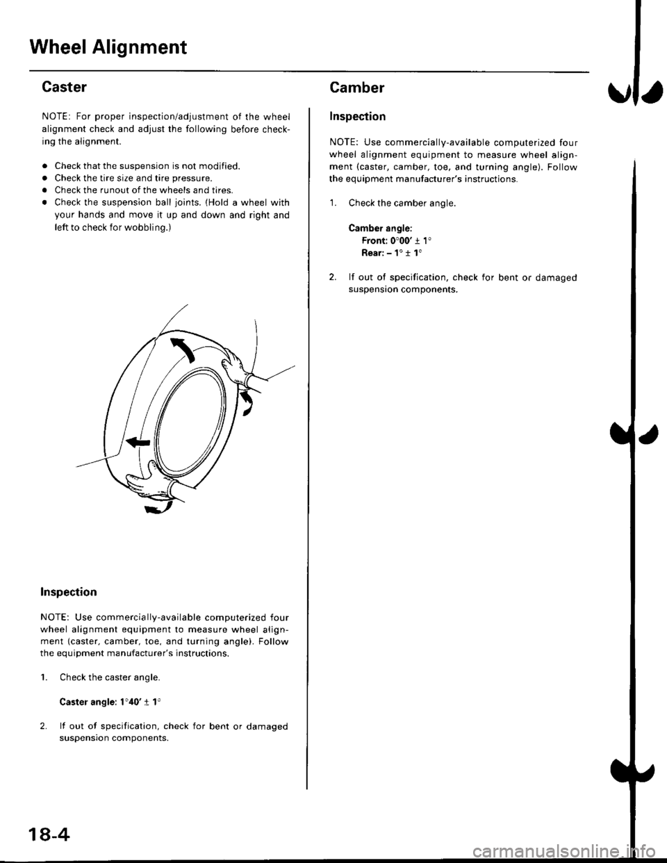
NOTE: For proper inspection/adjustment of the wheel
alignment check and adjust the following before check-
ing the alignment.
. Check that the suspension is not modified.
. Check the tire size and tire pressure.
. Check the runout of the wheels and tires.
. Check the suspension ball ioints. {Hold a wheel with
your hands and move it up and down and right and
left to check for wobbling.)
Inspection
NOTE: Use commercia lly-available computerized four
wheel alignment equipment to measure wheel align-
ment {caster. camber, toe, and turning angle). Follow
the equiDment manufacturer's instructions.
Check the caster angle.
Caster angle: 1',10' I 1'
lf out of specification, check for bent or damaged
suspensron components.
2.
1.
18-4
Camber
lnspection
NOTE: Use commercially-available computerized four
wheel alignment equipment to measure wheel align-
ment (caster, camber, toe, and turning angle). Follow
the equipment manufacturer's instructions.
1. Check the camber angle.
Camber angle:
Front: 0'00' j 1"
Rear:-1"11"
2. lf out ol specification, check for bent or damaged
suspensron components.
Page 1129 of 2189
?
Front Toe Inspection/Adiustment
NOTE: Use commercially-available computerized four
wheel alignment equipment to measure wheel align-
ment (caster, camber, toe, and turning angle). Follow
the equipment manufacturer's instructions.
1. Check the tire pressure.
Center steering wheel spokes.
Check the toe with the wheels pointed straight
a head.
Front toe: lN 1 1 2 mm llN l/16 r 1/16 inl
- lf adjustment is required, go on to step 4.
- lf no adjustment is required, remove alignment
equrpmenr.
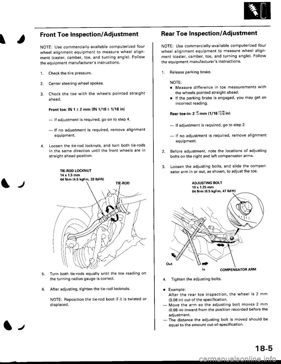
Loosen the tie-rod locknuts, and turn both tie-rods
in the same direction until the front wheels are in
straight ahead position.
TIE.ROD LOCKNUT'14 x 1.5 mm
4.
tJ
6.
Turn both tie-rods equally until the toe readang on
the turning radius gauge is correct.
After adjusting, tighten the tie-rod locknuts.
NOTE: Reposition the tie-rod boot if it is twisted or
displaced.
4,1 N.m {4.5 kgf.m, 33 lb{.ft)
2.
Rear Toe Inspection/Adiustment
NOTE: Use commercially-available computerjzed Iour
wheel alignment equjpment to measure wheel align-
ment (caster, camber, toe, and turning angle). Follow
the equipment manufacturer's instructions.
1. Release parking brake.
NOTE:
a Measure difference in toe measurements wlth
the wheels pointed straight ahead.
. if the parking brake is engaged, you may get an
incorrect readang,
Rear toe-in: 2 11 mm ttltollllS int
- lf adjustment is required, go to step 2.
- lf no adjustment is required, remove alignment
equipment.
Before adjustment, note the locations of adiusting
bolts on the right and left compensator arms
Loosen the adjusting bolts, and slide the compen
sator arm in or out. as shown, to adjust the toe
ADJUSTING BOLT10 x 1.25 mm
In CoMPENSAToR ARM
4. Tighten the adiusting bolts
. Example:
After the rear toe inspection, the wheel is 2 mm
(0.08 in) out of the specification.- Move the arm so the adjusfing bolt moves 2 mm
(0.08 in) inward trom the position recorded before the
adjustment.- The distance the adjusting bolt is moved should be
equal to the amount out-of-specification.
64 N.m 16.5 ksf m, 47 lbtft)
18-5
Page 1130 of 2189
Wheel Alignment
Turning Angle Inspection
NOTEr Use commercially-available computerized four
wheel alignment equipment to measure wheel align-
ment (caster, camber, toe, and turning angle). Follow
the equipment manufacturer's instructions.
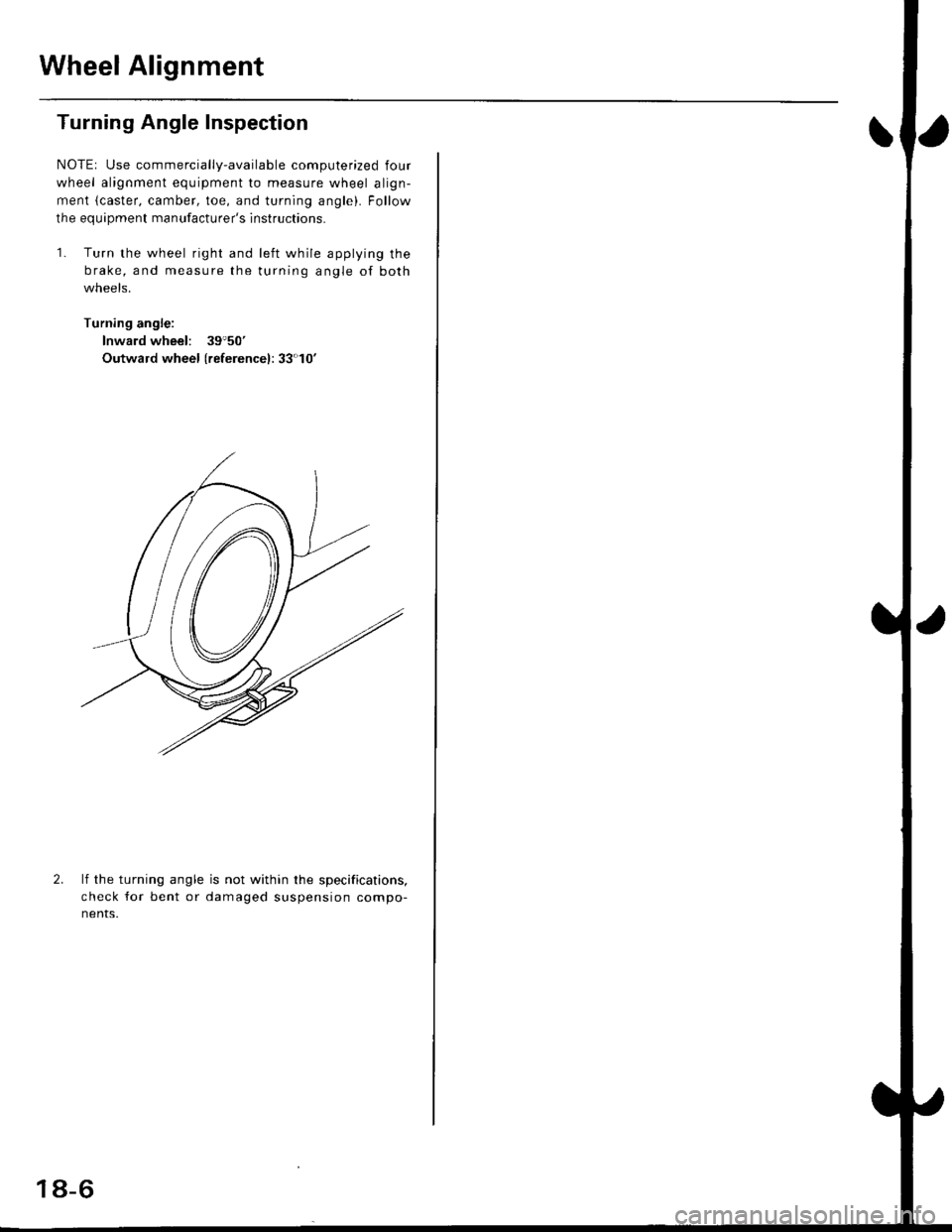
'1. Turn the wheel right and left while applying the
brake, and measure the turning angle of both
wneets.
Turning angle:
lnward wheel: 39'50'
Outwald wheel (ref erencel: 33'10'
2.lf the turning angle
check for bent or
nents,
is not within the specifications,
da m aged suspension compo-
18-6
Page 1149 of 2189
T
11.
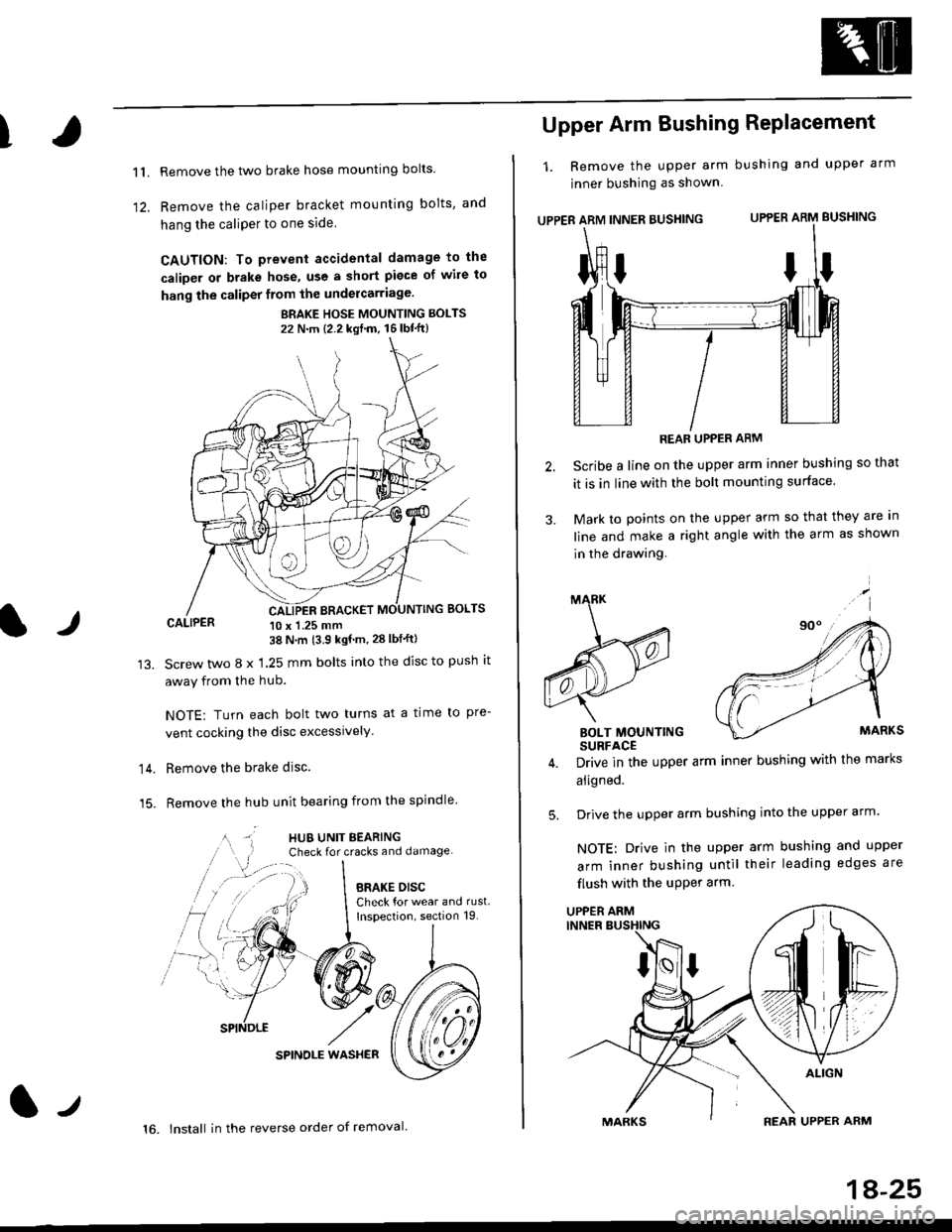
1)
Remove the two brake hose mounting bolts
Remove the caliper b.acket mounting bolts, and
hang the caliPer to one side
CAUTION: To prevent accidental damage to the
caliper or brake hose, use a short piece of wile to
hang the caliper from the undercarriage.
BRAKE HOSE MOUNTING BOLTS
22 N'm {2.2 kgf'm, 16lbt"ft}
CALIPER 10 x 1.25 mm38 N'm (3.9 kgf'm, 28 lbf'ftl
Screw two 8 x 1.25 mm bolts into the disc to push it
away from the hub.
NOTE: Turn each bolt two turns at a time to pre-
vent cocking the disc excessively.
Remove the brake disc.
Remove the hub unit bearing from the spindle
SPINOLE WAS}IER
lr
14.
15.
lt
16. lnstall in the reverse order of removal.
1A-25
Upper Arm Bushing RePlacement
1. Remove the upper arm bushing and upper arm
jnner bushing as shown
UPPER ARM INNER BUSHING UPPER ARM BUSHING
REAR UPPER ARM
Scribe a line on the upper arm inner bushing so that
it is in line with the bolt mounting surface
Mark to points on the upper arm so that they are In
line and make a right angle with the arm as shown
in the drawing.
BOLT MOUNTINGSURFACE
Drive in the upper arm inner bushing with the marks
aligned.
Drive the upper arm bushing into the upper arm
NOTE: Drive in the upper arm bushing and upper
arm inner bushing until their leading edges are
flush with the uPPer arm
ttI
5.
UPPER ARM
Page 1252 of 2189
Doors
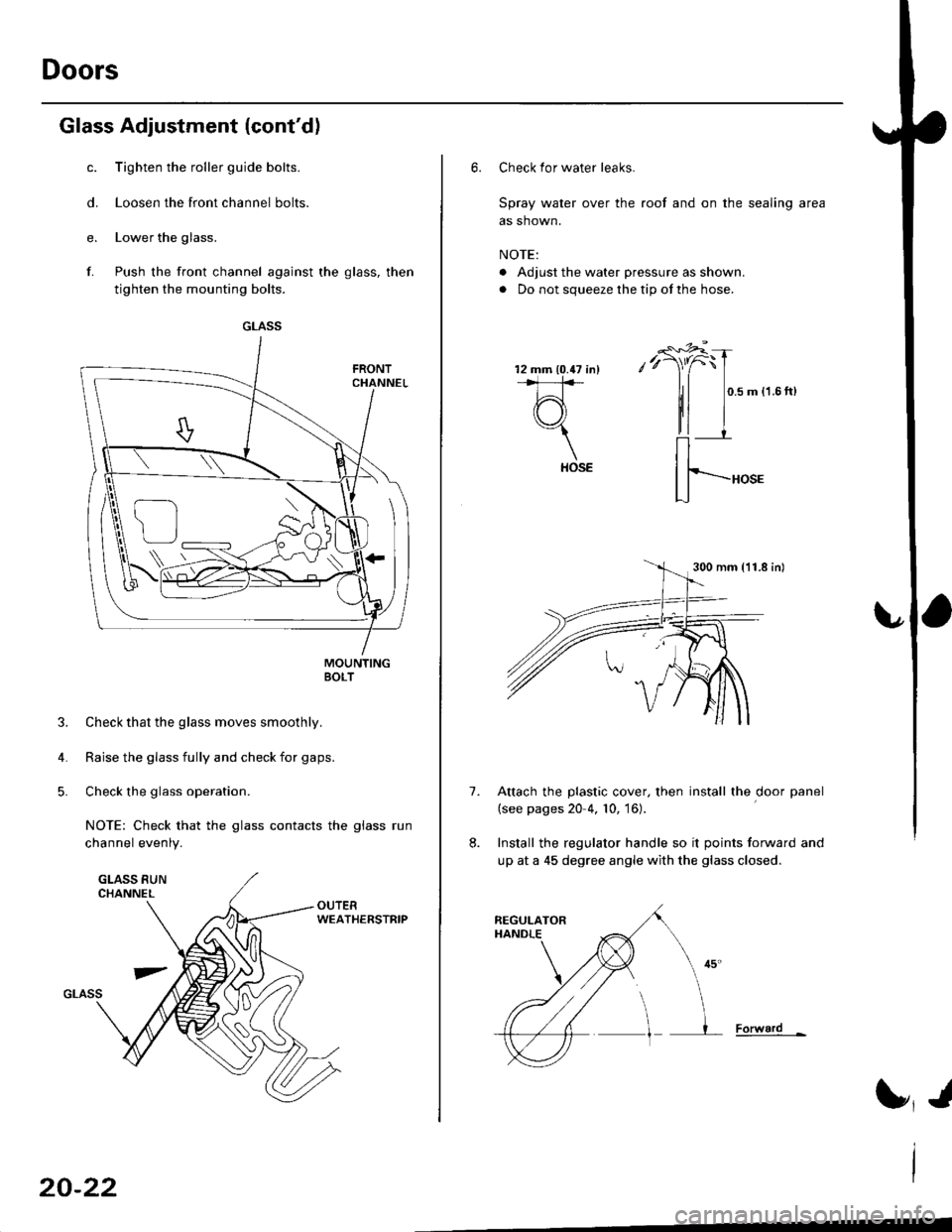
Glass Adjustment {cont'd)
c. Tighten the roller guide bolts.
d. Loosen the front channel bolts.
e. Lower the glass.
f. Push the front channel against the glass, then
tighten the mounting bolts.
MOUNTINGBOLT
3. Check that the glass moves smoothly.
4. Raise the glass fully and check for gaps.
5. Check the glass operation.
NOTE: Check that the glass contacts the glass run
channel evenly.
WEATHERSTRIP
GLASS
U
-\,
20-22
6. Check for water leaks.
Spray water over the roof and on the sealing area
as shown.
NOTE:
. Adjust the water pressure as shown.
. Do not squeeze the tip of the hose.
0.5 m {1.6ft)
HOSE
Attach the plastic cover, then install the door panel
(see pages 20 4, 10, 16).
Install the regulator handle so it points forward and
up at a 45 degree angle with the glass closed.
Forward -
1.
HOSE
300 mm {11.8 in)
Page 1261 of 2189
3
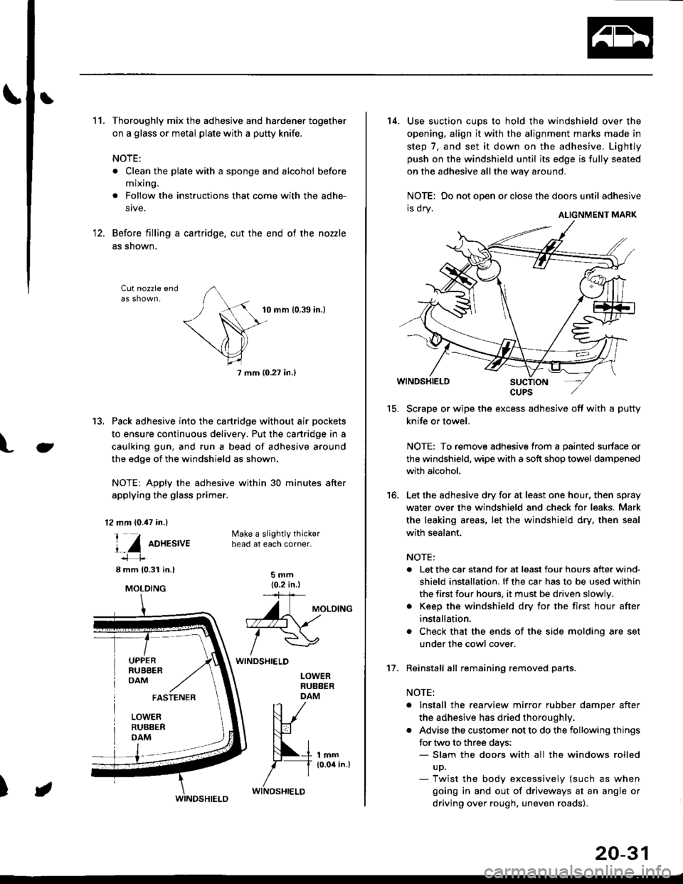
11.Thoroughly mix the adhesive and hardener together
on a glass or metal plate with a putty knife.
NOTE:
. Clean the plate with a sponge and alcohol before
mixing.
. Follow the instructions that come with the adhe-
stve.
Before filling a cartridge. cut the end of the nozzle
as shown.
Cut nozzle end
tu
10 mm 10.39 in.)
7 mm (0.27 in.l
13. Pack adhesive into the cartridge without air pockets
to ensure continuous delivery. Put the cartridge in a
caulking gun, and run a bead of adhesive around
the edge of the windshield as shown.
NOTE: Apply the adhesive within 30 minutes after
applying the glass primer.
12 mm (0.47 in.)
l_Z oo*.t,ut
8 mm 10.31 in.l
UPPERRUBBERDAM
Make a slightly thickerbead at each corner.
5mm(0.2 in )='+
A\uloto^o. -.\
/wWINDSHIELD
LOWEBRUBBERDAM
lmm10.04 in.l
FASTENER
LOWERRUBBERDAM
)
MOLDING
WINDSHIELD
20-31
15.
16.
14. Use suction cups to hold the windshield over the
opening, align it with the alignment marks made in
step 7, and set it down on the adhesive. Lightly
push on the windshield until its edge is fully seated
on the adhesive all the way around.
NOTE: Do not open or close the doors until adhesive
ri vI Y ALTGNMENT MARK
Scrape or wipe the excess adhesive off with a putty
knife or towel.
NOTE: To remove adhesive from a painted surface or
the windshield, wipe with a soft shop towel dampened
with alcohol.
Let the adhesive dry for at least one hour, then spray
water over the windshield and check for leaks. Mark
the leaking areas, let the windshield dry, then seal
with sealant.
NOTE:
. Let the car stand for at least four hours after wind-
shield installation. lf the car has to be used within
the first four hours, it must be driven slowly.
. Keep the windshield dry for the first hour after
installation.
. Check that the ends of the side molding are set
under the cowl cover.
Reinstall all remaining removed parts.
NOTE:
. Install the rearview mirror rubber damper after
the adhesive has dried thoroughl',.
. Advise the customer not to do the following things
for two to three days:- Slam the doors with all the windows rolled
up.- Twist the body excessively (such as when
going in and out of driveways at an angle or
driving over rough, uneven roads).
't7.
Page 1265 of 2189
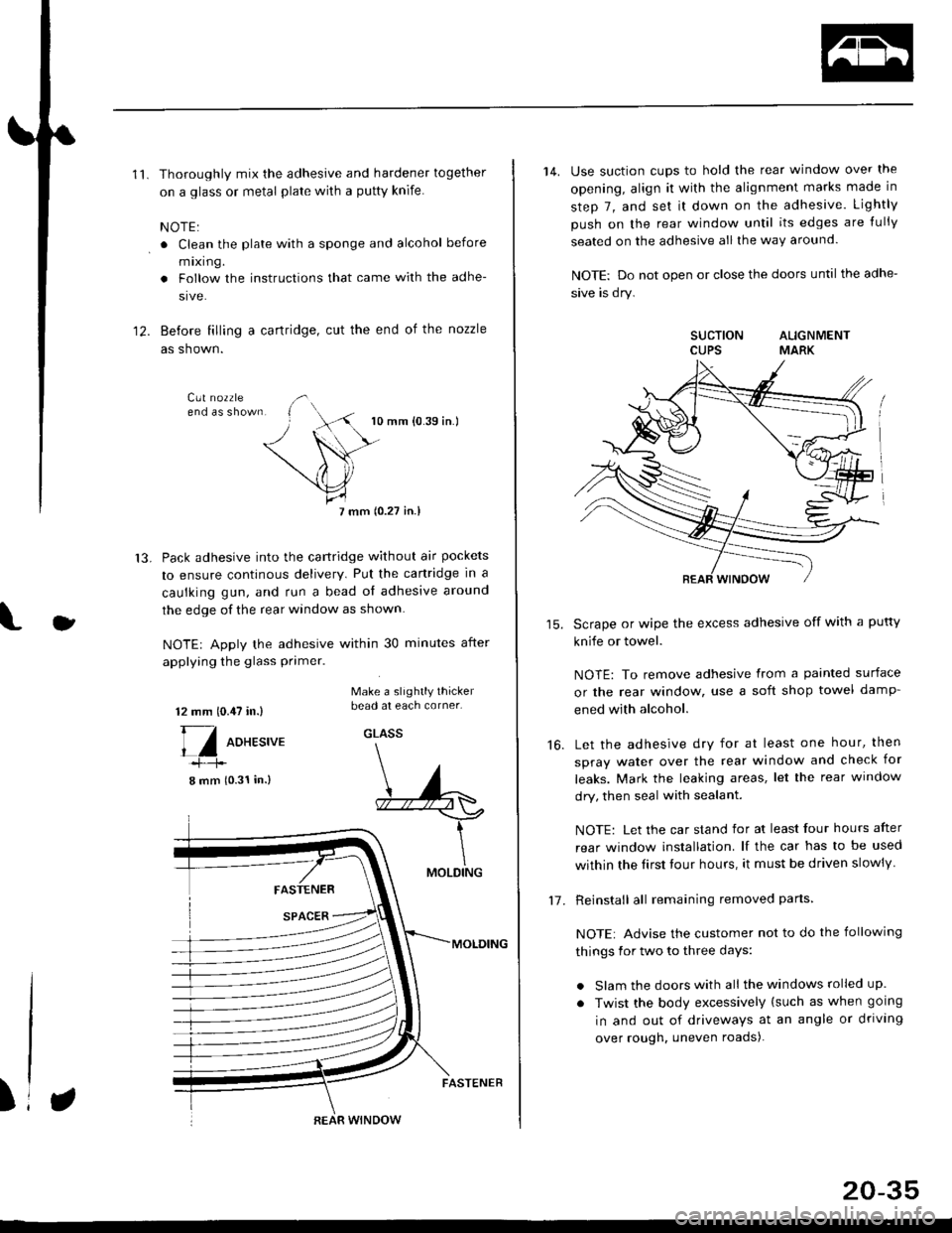
'11.Thoroughly mix the adhesive and hardener together
on a glass or metal plate wilh a putty knife.
NOTE:
. Clean the plate with a sponge and alcohol before
mixing.
. Follow the instructions that came with the adhe-
sive.
Before filling a cartridge, cut the end of the nozzle
as shown.
10 mm {0.39 in.)
7 mm (0.27 in.l
Pack adhesive into the cartridge without air pockets
to ensure continous delivery. Put the canridge in a
caulking gun, and run a bead ol adhesive around
the edge of the rear window as shown.
NOTE| Apply the adhesive within 30 minutes after
applying the glass primer.
12.
13.
J
12 mm 10.,U in.)
[/ oo*r.,u.
8 mm (0.31 in.)
Make a slightly thickerbead at each corner.
GLASS
FASTENER
SPACER
MOLDING
MOLDING
)REAR WINDOW
FASTENER
20-35
14. Use suction cups to hold the rear window over the
opening, align it with the alignment marks made in
step 7, and set it down on the adhesive. Lightly
push on the rear window until its edges are {ully
seated on the adhesive all the way around.
NOTE: Do not open or close the doors until the adhe-
sive is dry.
SUCTION ALIGNMENTCUPS MARK
Scrape or wipe the excess adhesive off with a putty
knife or towel.
NOTE: To remove adhesive from a painted surface
or the rear window, use a soft shop towel damp-
ened with alcohol.
Let the adhesive dry for at least one hour, then
spray water over the rear window and check for
leaks. Mark the leaking areas, let the rear window
dry, then seal with sealant.
NOTE: Let the car stand for at least four hours after
rear window installation. lf the car has to be used
within the Iirst tour hours, it must be driven slowly
Reinstall all remaining removed parts
NOTE: Advise the customer not to do the following
things for two to three days:
. Slam the doors with all the windows rolled up.
. Twist the body excessively (such as when going
in and out of driveways at an angle or driving
over rough. uneven roads).
16.
1-7 .
Page 1270 of 2189
Rear WindowOuarter Glass
Installation {cont'd)
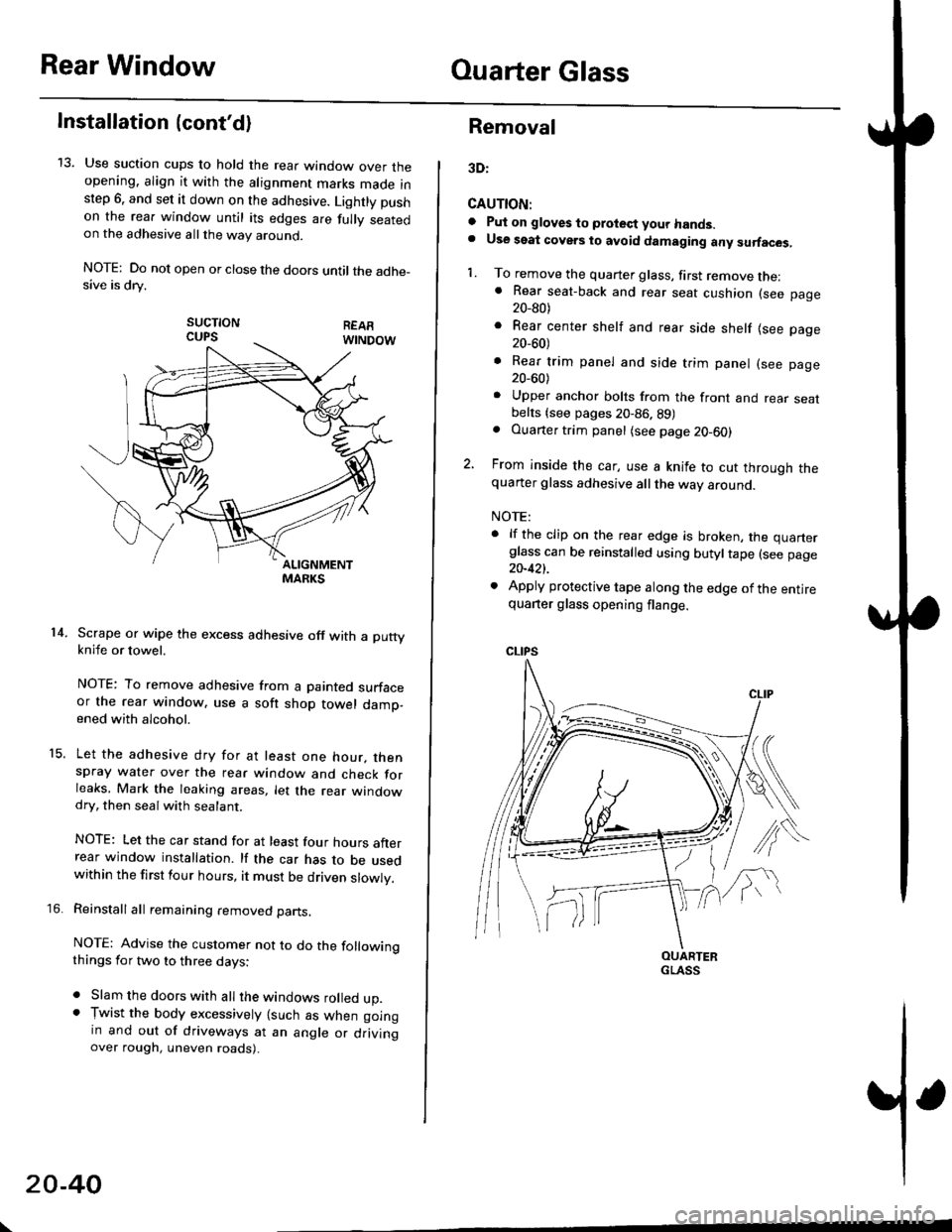
13. Use suction cups to hold the rear window over theopening. align it with the alignment marks made inslep 6. and set it down on the adhesive. Lightly pushon the rea. window until its edges are fully seatedon the adhesive allthe way around.
NOTE: Do not open or close the doors until the adhe_sive is drv.
sucTtoNCUPS
Scrape or wipe the excess adhesive off with a puttyknife or towel.
NOTE: To remove adhesive from a painted surfaceor the rear window. use a soft shop towel damp-ened with alcohol.
Let the adhesive dry for at least one hour. thenspray water over the rear window and check forleaks, Mark the leaking areas, let the rear windowdry, then seal with sealant.
NOTE: Let the car stand for at least four hours afterrear window installation. lf the car has to be usedwithin the first four hours, it must be driven slowly.
Reinstall all remaining removed parts.
NOTE: Advise the customer not to do the followingthings for two to three days:
. Slam the doors with all the windows rolled up.. Tr,vist the body excessively lsuch as when goingin and out of driveways at an angle or drivingover rough, uneven roads).
14.
15.
\
20-40
Removal
3D:
CAUTION:
a Pul on gloves to protect your hands.. Use seat covers to avoid damaging any surfaces,
1. To remove the quarter glass, first remove the:. Rear seat-back and rear seat cushion (see page20_80)
. Rear center shelf and rear side shelf lsee page20_60)
. Rear trim panel and side trim panel (see page20_60)
. Upper anchor bolts from the front and rear seatbelts {see pages 20-86. 89). Ouarter trim panel (see page20-60)
2, From inside the car, use a knife to cut through thequarter glass adhesive all the way around.
NOTE:
. lf the clip on the rear edge is broken, the quarterglass can be reinstalled using butyltape (see page20-421.
. Apply protective tape along the edge of the entirequarter glass opening flange.
OUARTERGLASS
Page 1274 of 2189
Ouarter Glass
Installation (cont'd)
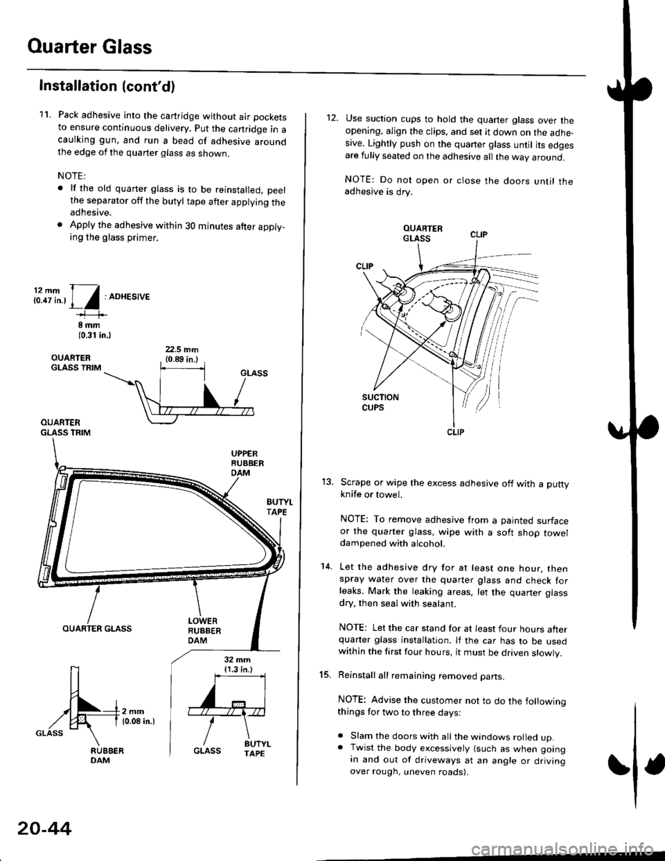
11. Pack adhesive into the cartridge without air pockets
to ensure continuous delivery. put the canridge in acaulking gun, and run a bead of adhesive aroundthe edge of the quarter glass as shown.
NOTE:
. lf the old quarter glass is to be reinstalled, peelthe separator off the butyl tape after applying theadhesive.
. Apply the adhesive within 30 minutes after apply_ing the glass primer.
i:.8i".,1/:ADHES,'E
8 rnm(0.31 in.l
OUARIERGLASS TRIM
OUARTERGLASS TFIM
BUTYI.TAPE
OUARTER GLASS
[-4m,^,GLASS \
32 mm{1.3 in.)
''='I
'"r"\
/ drt".GLASS TAPE
20-44
12. Use suction cups to hold the quarter glass over theopening, align the clips, and set it down on the adhe-sive. Lightly push on the quaner glass until its edgesare fully seated on the adhesive all the way around.
NOTE: Do not open or close the doors until theadhesive is drv.
Scrape or wipe the excess adhesive off with a puttyknife or towel.
NOTE: To remove adhesive from a painted surfaceor the quarter glass, wipe with a soft shop toweldampened with alcohol.
Let the adhesive dry for at least one hour, thenspray water over the quarter glass and check forleaks. Mark the leaking areas, let the quarter glass
dry, then seal with sealant.
NOTE: Let the car stand for at least four hours afterquarter glass installation. lf the car has to be usedwithin the first four hours, it must be driven slowly.
Reinstall all remaining removed parts.
NOTE: Advise the customer not to do the followingthings for two to three days:
. Slam the doors with all the windows rolled up.. Twist the body excessively (such as when goingan and out of driveways at an angle or drivingover rough, uneven roads).
15.
14.
CLIP