tools HONDA CIVIC 1996 6.G User Guide
[x] Cancel search | Manufacturer: HONDA, Model Year: 1996, Model line: CIVIC, Model: HONDA CIVIC 1996 6.GPages: 2189, PDF Size: 69.39 MB
Page 166 of 2189
VTEC Rocker Arms
4.
Inspection Using Special Tools (cont,dl
Loosen the valve on the regulator and apply thespecified air pressure.
Specified Air Pressuro:
250 kPa {2.5 kgtlcm,, 36 psil- 490 kPa {5.0 kgtcm,, 7t psil
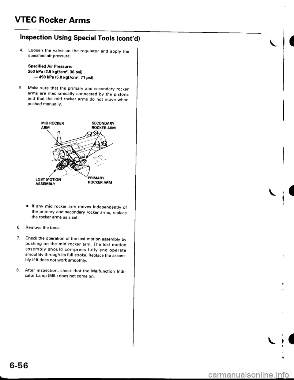
Make sure that the primary and secondary rockerarms are mechanically connected by the pistonsand that the mid rocker arms do no. move wnenpushed manually.
SECONDARYROCKER ARM
. lf any mid rocker arm moves independently ofthe primary and secondary rocker arms, replacethe rocker arms as a set.
Remove the tools.
Check the operation of the lost motion assembly bypushing on the mid rocker arm. The lost motionassembly should compress fully and operatesmoothly through its full stroke. Replace the assem_bly if it does not work smoothly.
After inspection. check that the Malfunction Indi_cator Lamp {MlL) does not come on.
7.
6-56
I
ll
;l
Page 198 of 2189
Engine Block
Speciaf Tools ..........." 7-2
lllustlated Index ...................."..'.......... 7-3
Flywheel and Drive Plate
Repf acement """'.' 7-7
Connecting Rod and Crankshaft
End Play ..........."....7-8
Main Bearings
Clearance ............... 7-9
Selection ................7-10
Connecting Rod Bearings
clearance ....'.......... 7-11
Selection ................ 7-11
Pistons and Crankshaft
Removaf ................. 7 -12
Crankshaft
Inspection ."".........7-14
Pistons
Inspection ......"'.....7-15
fnstaffation .............7-23
Cylinder Block
lnspec'tion ..............7-16
Bore Honing ..........7-17
Piston Pins
Removal ...,...........'.7-17
lnstallation .............7-18
Inspection .'............7-19
Connecting Rods
Selection ................7-18
Piston Rings
End Gap ..........".."' 7'2O
Repfacement .........7-2O
Ring-to-Groove Clearance ...........'.'. 7 -21
Afignment .......""'.. 7'21
Crankshaft Oil Seal
fnstaffation .............7-22
Crankshaft
fnstaffation ..-.-..'.".' 7'23
Oil Pan
lnstallation .............7-26
Oil Seals
fnstaffation ....""""' 7-29
r-f
Page 199 of 2189
Special Tools
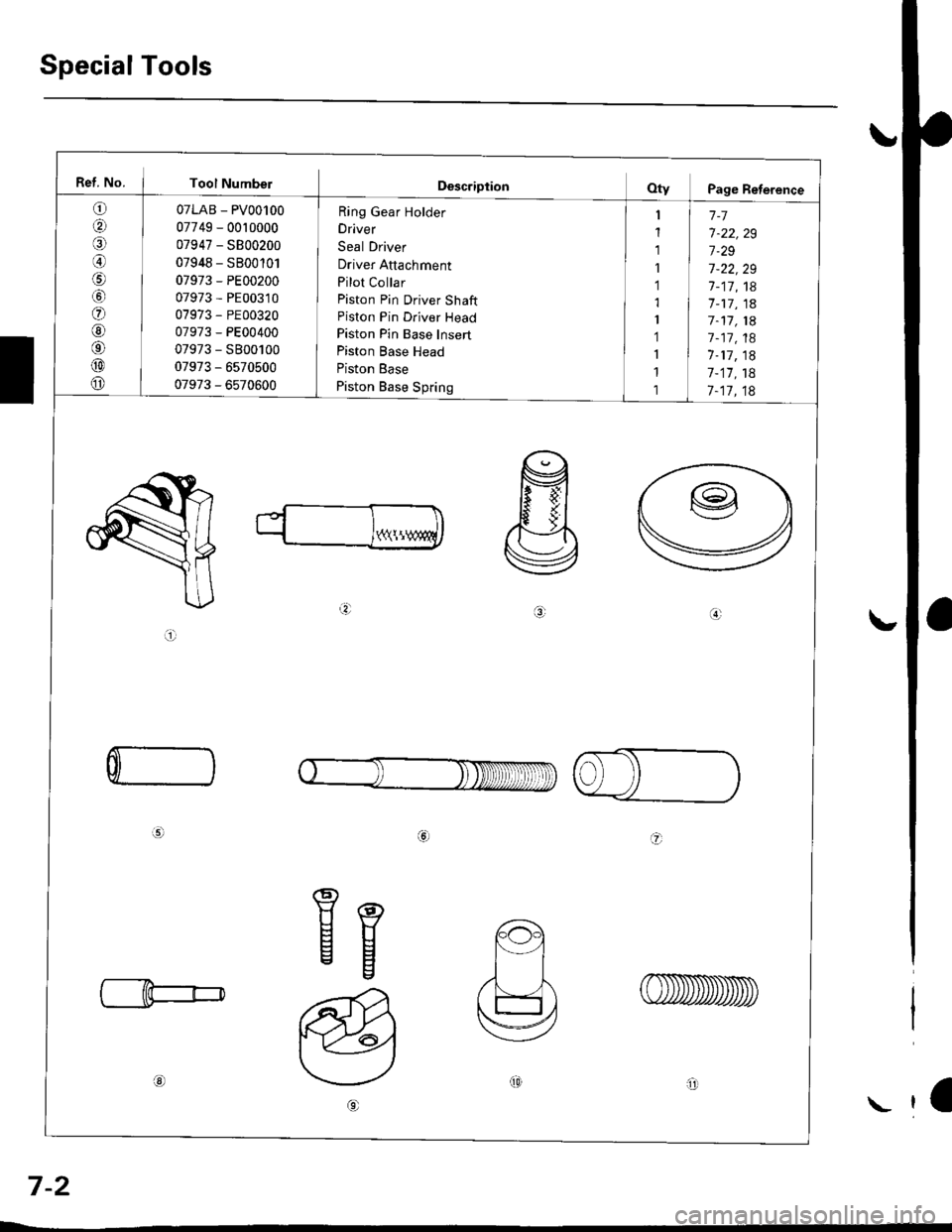
Ref. No. I Tool Numbel
o
aal
@
o
@6'
@
o
07LAB - PV00100
07749 - 0010000
07947 - SB00200
07948 - SB00'101
07973 - PE00200
07973 - PE00310
07973 - PE00320
07973 - PE00400
07973 - S800100
07973 - 6s70500
07973 - 6570600
Ring Gear Holder
Driver
Seal Driver
Driver Attachment
Pilot Collar
Piston Pin Driver Shaft
Piston Pin Driver Head
Piston Pin Base Insert
Piston Base Head
Piston Base
Piston Base Spring
1-7
7-22,29
7.29
7-22,29
7-17,18'7 -17, 1a
7-11, 1A
7 -17, 18
1-17, 18
7-17,18
7-17,18
Y(\!
a.:
ai
C
a
Eg
ot0arll
a
7-2
\
Page 214 of 2189
Cylinder BlockPiston Pins
Bore Honing
1.Measure cylinder bores as shown on page 7-16. lf the
block is to be reused, hone the cylinders and remea-
sure the bores.
Hone cylinder bores with honing oil 8nd a fine (400
grit) stone in a 60 degree cross-hatch pattern.
NOTE:
. Use only a rigid hone with 400 grit or finer stone
such as Sunnen, Ammco, or equivalent.
. Do not use stones lhat are worn or broken.
When honing is complete, thoroughly clean the
engine block of all metal particles. Wash the cylin-
der bores with hot soapY water, then dry and oil
immediately to prevent rusting.
NOTE: Never use solvent. it will only redistribute the
grit on the cylinder walls.
lf scoring or scratches are still present in cylinder
bores after honing to the service limit, rebore the
cylinder block.
NOTE: Some light vertical scoring and scratching is
acceptable if it is not deep enough to catch your fin-
gernail and does not run the full length of the bore.
CYLINOES BLOCK
CYLINDER
NOTE:
. After honing, clean the cylinder thoroughly with
soapy warer.
. Onlv a scored or scratched cylinder bore must be
noneo.
Removal
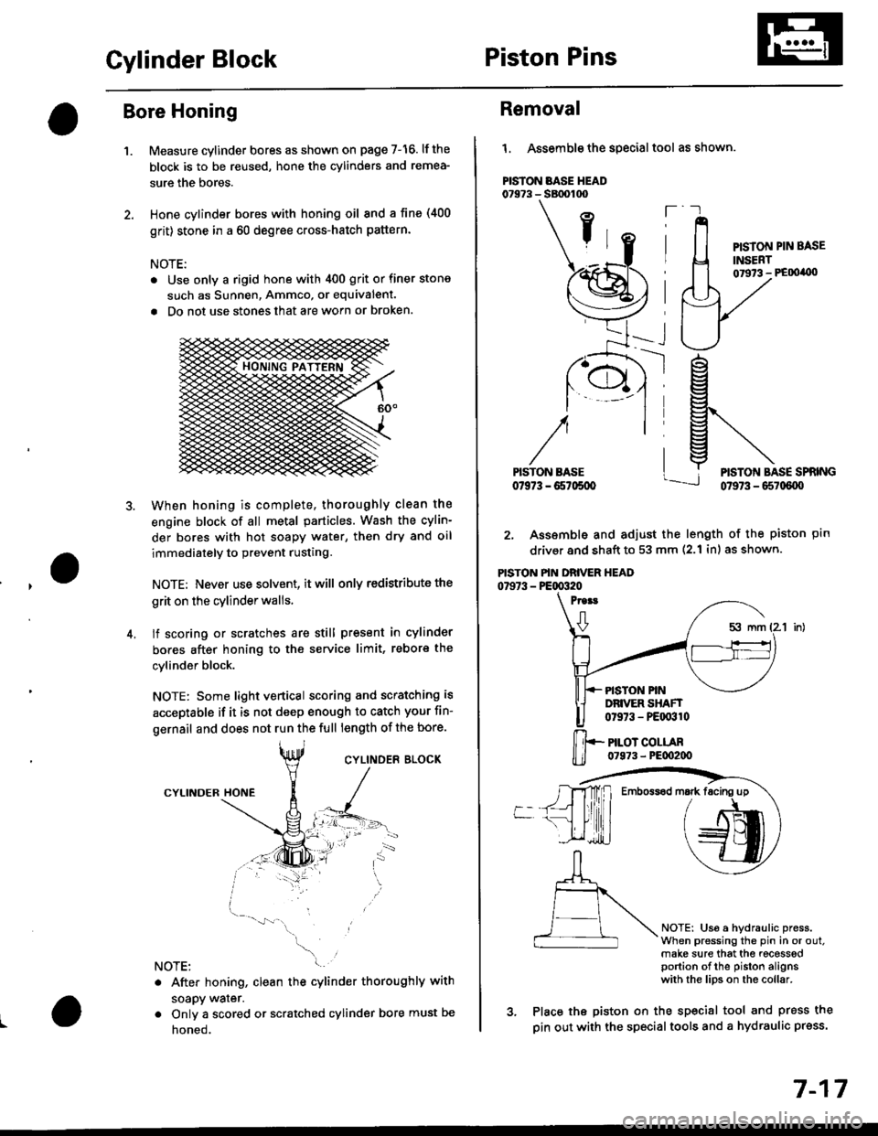
l. Assemble the special tool as shown.
PISTON BASE HEAD07973 - SBtx)too
ft
PISTON PIN BASE
INSERT01973 - PE00'0)
ptn
NOTEi Us6 a hydraulic press.When pressing the pin in or out.make sure that the recesssdportion of the piston alignswith the lips on the collar.
rg
g\
lj*N*,""
2. Assemble and adjust the length of the piston
driver and shaft to 53 mm (2.1 inl as shown.
PISTON PIN DRIVER HEAD07973 - PE00320
Proat
0
PISTON PINDRIVER SHAFT0t973 - PEqr310
PILOT COLLAR07973 - PE00200
3. Place the piston on the sp€cial tool and press the
pin out with the special tools and a hydraulic press.
Emboss6d mark facing up
7-17
Page 219 of 2189
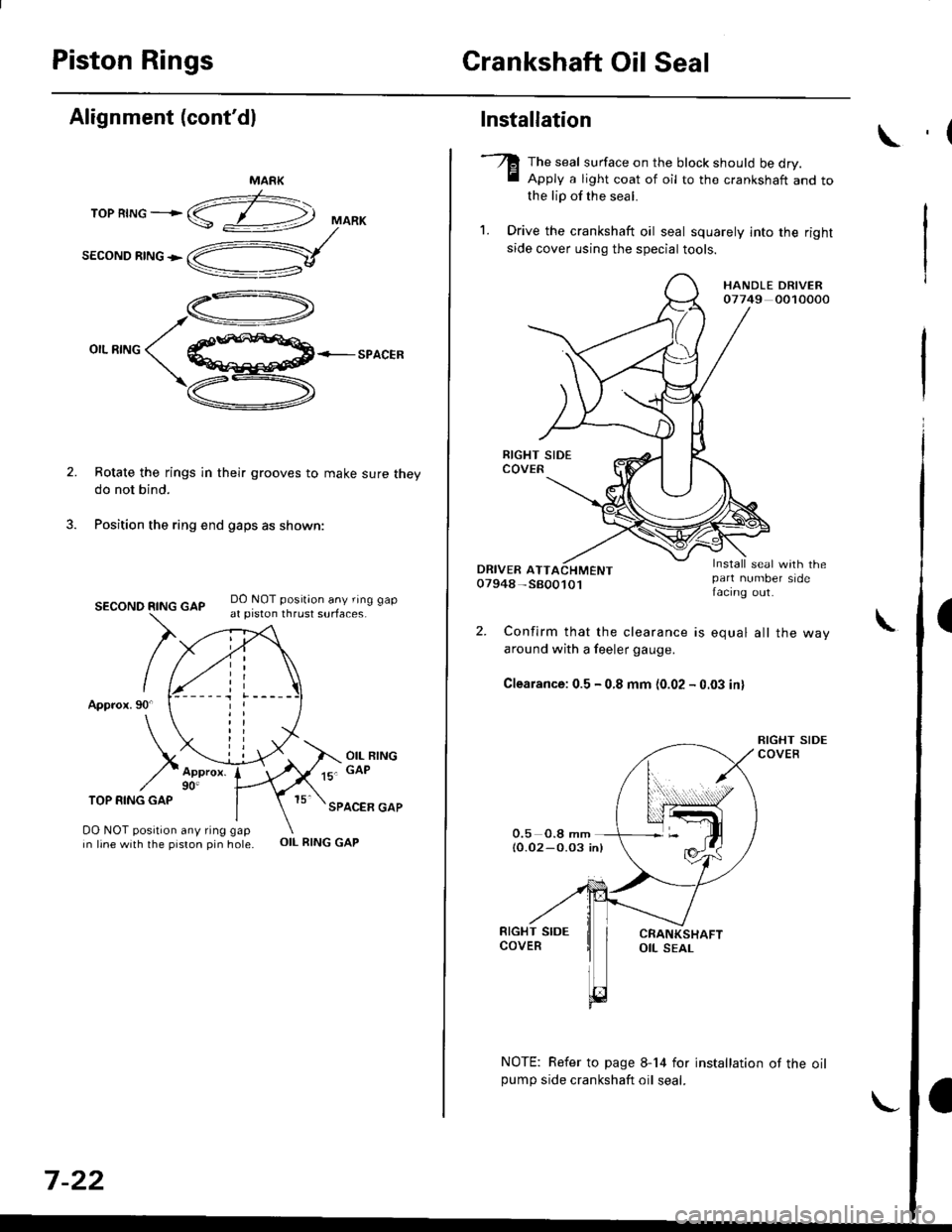
Piston RingsCrankshaft Oil Seal
Alignment (cont'dl
TOP RING ---.>
SECOND RING >
MARK
,a-)
/\_4
o,.r^o( qffi<--sPACER
\Z-.
v
Rotate the rings in their grooves to make sure theydo not bind.
Position the ring end gaps as shown:
DO NOT position any ring gapat piston thrust surfaces.
DO NOT position any ring gapin line with the piston pin hole.OIL RING GAP
SECOND RING GAP
Approx.90
TOP RING GAP
7-22
Installation
The seal surface on the block should be dry.Apply a light coat of oil to the c.ankshaft and tothe lip of the seal.
1. Drive the crankshaft oil seal squarely into the right
side cover using the special tools.
HANDLE DRIVER07749 0010000
seal with thepan number sidefacing out.
Confirm that the clearance is equal all the way
around with a feeler gauge.
Clearance:0.5 - 0.8 mm (0.02 - 0.03 inl
NOTE: Refer to page 8-14 for installation of the oilpumo side crankshaft oil seal.
,(
\
Page 227 of 2189
Engine Lubrication
SpecialTools .......... "'.""".8'2
lllustrated Index ........... .'..' 8-3
Engine Oil
Inspection .....'......"....."'. 8-6
Replacement........'......".'.'..."...."......" 8-7
OilFilter
Rep1acement...............".'...'..'.....'.'...". 8-8
Oil Pressure
Testing '.....' 8-9
OilJet (B16A2 engine)
Inspection ...'.'......"...."'..8-10
OilPump
overhaul.'... .....'...'..'."""' 8-11
Removal/lnspection/lnstallation ..'.... 8-1 3
Page 228 of 2189
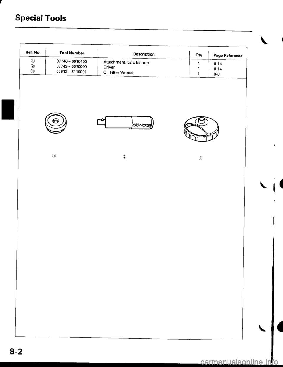
Special Tools
Ref. No. I Toot Number
07746 - 0010400
07749 - 0010000
07912 - 6110001
Attachment, 52 x 55 mmDriver
Oil Filter Wrench
o6\,6
\
ll
a
8-2
\
Page 271 of 2189
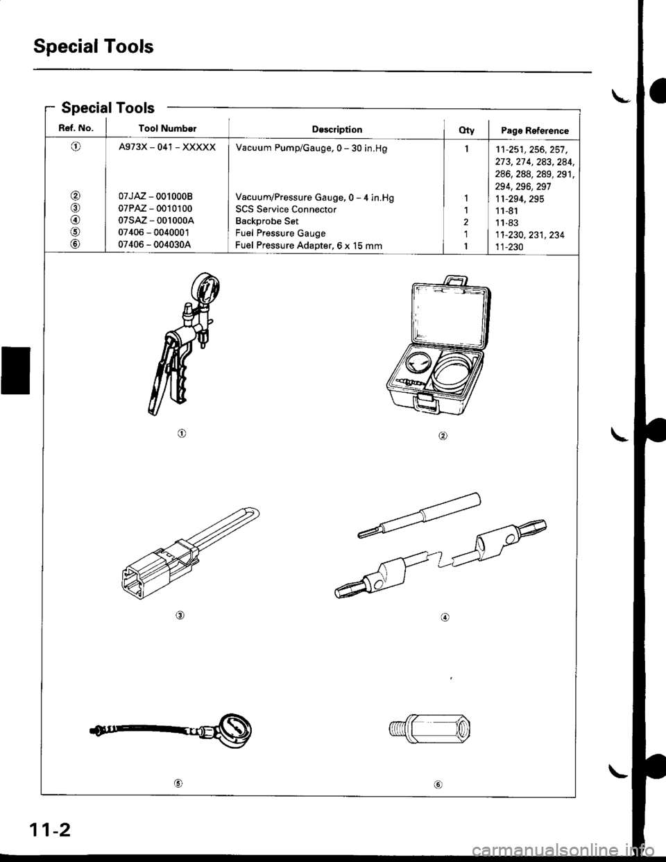
Special Tools
a\-Special Tools
R€f. No. I Tool NumberDsscriptionOty I Pagr Reference
O
@/n
@
@
@
A973X_041 _ XXXXX
07JAZ - 0010008
07PAZ - 0010100
07sAz - 001000A
07406 - 0040001
07406 - 0040304
Vacuum Pump/Gauge, 0 - 30 in.H9
Vacuum/Pressure Gauge, 0 - 4 in.Hg
SCS Service Connector
Backprobe Set
Fuel Pressure Gauge
Fuel Pressure Adapter,6 x 15 mm
I
I
1
2
1
I
11-251,256, 257 ,273,27 4, 283,284,
286, 288, 289, 291,
294,296,297
11-294,295
11-81
11-83
1'�t-230, 231, 234
11-230
ta
1n\Y
11-2
Page 496 of 2189
I
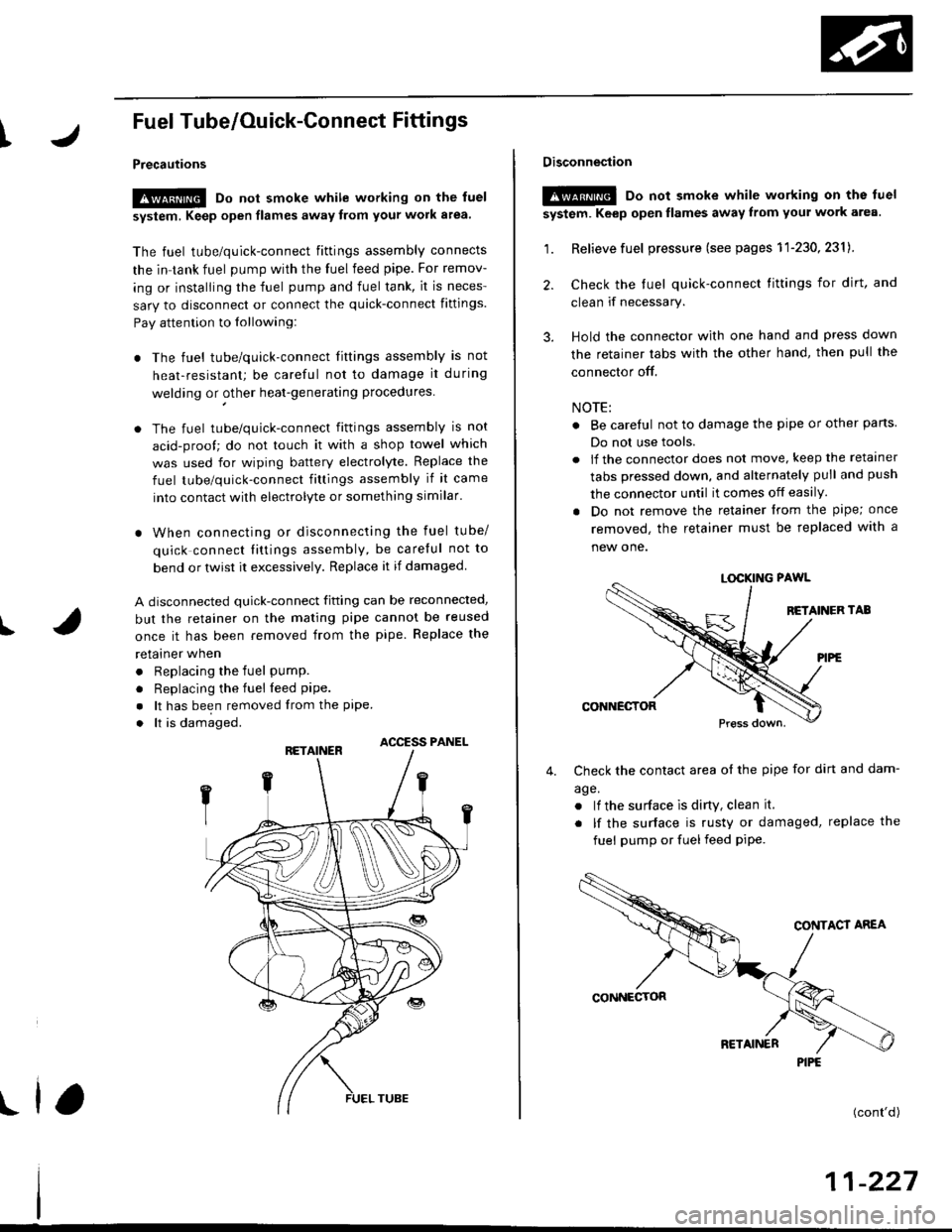
Fuel Tube/Ouick-Gonnect Fittings
Precautions
!@ Do not smoke while working on the fuel
system, Keep open flames away from your work a.ea'
The fuel tube/quick-connect fittings assembly connects
the in tank fuel pump with the fuel feed pipe. For remov-
ing or installing the fuel pump and fuel tank, it is neces-
sary to disconnect or connect the quick-connect fittings.
Pay attention to lollowing:
. The fuel tube/quick-connect fittings assembly is not
heat-resistant; be careful not to damage it during
welding or other heat-generating procedures
. The fuel tube/quick-connect fittings assembly is not
acid-proof; do not touch it with a shop towel which
was used for wiping battery electrolyte. Replace the
fuel tube/quick-connect fitlings assembly if it came
into contact with electrolyte or something similar.
. When connecting or disconnecting the fuel tube/
quick connect liltings assembly, be careful not to
bend or twist it excessively. Replace it if damaged
A disconnected quick-connect fitting can be reconnecled,
but the retainer on the mating pipe cannot be reused
once it has been removed from the pipe. Replace the
retatner wnen
. Replacing the fuel pump.
. Replacing the fuel leed pipe.
. lt has been removed lrom the PiPe.. lt is damaged.
ACCESS PANEL
I
Disconnestion
!@ Do not smoke while working on the luel
system. Keep open llames away lrom youl work area.
1. Relieve fuel pressure (see pages 11'230,2311.
2. Check the tuel quick-connect tittings for dirt, and
clean if necessary.
3. Hold the connector with one hand and press down
the retainer tabs with the other hand, then pull the
connector off.
NOTE:
o Be carelul not to damage the pipe or other pans
Do not use tools.
. lf the connector does not move, keep the retainer
tabs pressed down, and alternately pull and push
the connector until it comes off easily.
. Do not remove the retainer from the pape; once
removed, the retainer must be replaced with a
new one.
LOCKING PAWL
BETAINER TAB
CONNECTOR
Check the contact area o{ the pipe for dirt and dam-
age.
. lf the surface ls dirty, clean it.
. lf the surface is rusty or damaged, replace the
fuel pump or fuel feed piPe.
4.
(cont'd)
11-227
PIPE
Page 500 of 2189
tJFuel Pressure {'97 and later Models)
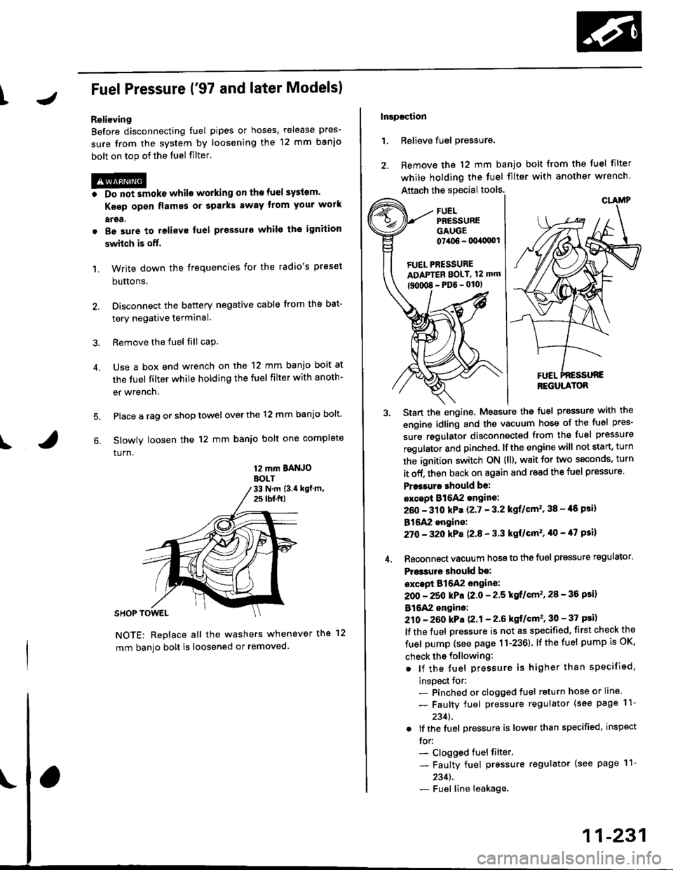
ReliGving
Before disconnecting tuel pipes or hoses, release pres-
sure from the system by loosening the 12 mm banjo
bolt on top of the fuel filter.
@o Do not smoke whilo working on the fuel sy3lom.
Ksgp op€n flames or sparks away tlom Your work
arga.
. Be sure to relieve fuel pressule while the ignition
swhch is off.
1. Write down the frequencies for the radio's preset
buttons,
2. Disconnect the battery negative cable from the bat-
tery negative terminal.
3. Remove the fuel fill cap.
Use a box end wrench on the 12 mm banjo bolt at
the fuel filter while holding the fuel filter with anoth-
er wrench.
Place a rag or shop towel over the 12 mm banio bolt.
Slowly loosen the 12 mm banjo bolt one complete
turn.
4.
I
12 mm BAtt OBOLT33 N.m (3.i1 kgf m,25 tbf.f0
NOTE: Replace all the washers whenever the 12
mm banio bolt is loosened or removed.
Inspaqtion
1. Relieve fuel pressure.
2. Remove the 12 mm banjo bolt from the fuel filter
while holding the fuel Jilter with another wrench
Attach the special tools.
3. Start the enginethe fuel Pressure with the
engine idling and the vacuum hose of the fuel pres-
sure regulator disconnected from the fuel pressure
regulator and pinched lfthe engine will not start, turn
the ignition switch ON {ll), wait for two seconds, turn
it off, then back on again and read the fuel pressure'
Pr$3uro ehould be:
excepi 816A2 sngine:
260 - 310 kPa {2'7 - 3.2 kgf/cm" 38 - {6 Fi}
B16A2 engine:
27O -32O kPa P.8 - 3'3 kgf/cm'�, '10 - 47 psi)
4. Reconnect vacuum hoso to the fuel pressure regulator'
Pre33ure 3hould be:
except B16A2 engin€:
2OO - 250 kPa {2.0 - 2'5 kgf/cm'�, 28 - 36 psi)
B16A2 engino:
210 - 260 kPa 121 - 2.6 ksf/cm'�, 30 - 37 psi)
lf the fuel pressure is not as specified, first check the
fuel pump (see page 11-236) lfthetuel pumpisoK,
check tho following:
. lf the fuel pressure is higher than specified,
inspect for:- Pinched or clogged fuel return hose or line.
- Faulty fuel pressure regulator (see page 11-
2341.
. lf the fuel pressure is lower than specified, inspect
for:- Clogged fuel filter.
- Faulty fuel pressure regulator (see page l1-
2341.- Fuel line leakage.
FUEL PRESSUREADAPTER BOLT, 12 mm
tguxt8-PD6-0101
CLAMP
REGULATOR
11-231