tools HONDA CIVIC 1996 6.G Repair Manual
[x] Cancel search | Manufacturer: HONDA, Model Year: 1996, Model line: CIVIC, Model: HONDA CIVIC 1996 6.GPages: 2189, PDF Size: 69.39 MB
Page 852 of 2189
Transmission Housing Bearings
L
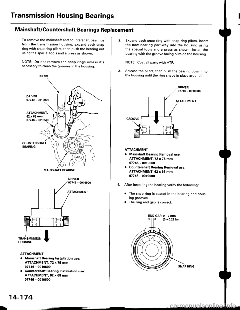
Mainshaft/Countershaft Bearings Replacement
To remove the mainshaft and countershaft bearings
from the transmission housing, expand each snap
ring with snap ring pliers, then push the bearing out
using the special tools and a press as shown.
NOTE: Do not remove the snap rings unless it's
necessary to clean the grooves in the housing.
DRIVER07749 - 0010000
ATTACHMENT,62x68mm
PRESS
\
07746 -
DFIVEB07749 - 0010000
TTACHMENT
ATTACHMENT
. Mainshaft Bearing Installation us€:
ATTACHMENT. 72 x 75 mm
07746 - 0010600. Countershaft Bearing Installation use:
ATTACHMENT, 62 x 68 mm
077/16 - 0010500
IRN{L{r.)n
\bZ
MAINSHAFT BEARING
L
14-174
SNAP RING
Expand each snap ring with snap ring pliers, insert
the new bearing part-way into the housing using
the special tools and a press as shown, Install thebearing with the groove facing outside the housing.
NOTE: Coat all parts with ATF.
Release the pliers, then push the bearing down intothe housing until the ring snaps in place around it.
07749 - 0010000
ATTACHMENT
. Mainshaft Bearing Removal use:
ATTACHMENT, 72 x 75 mm
077/16 - 0010600. Counte6haft Bsaring Removal use:
ATTACHMENT, 62 x 68 mm
07746 - 0010500
After installing the bearing verify the following:
. The snap ring is seated in the bearing and hous-
ing grooves.
. The ring end gap is correct.
(0 - 0.28 in)ENDGAP:0-7mm
Page 871 of 2189
Continuously Variable Transmission (CVTI
Special Tools ................ 14-194
Description .................... 14-195
Clutches/Reverse Brake/Planetary
Gear/Pulleys .......... 14-198
power Flow ..............,..... 14-200
Electronic Control SYstem(,96 - 98 Modets) ......14-203
Electronic Control System
('99 - oo Models) " 14-205
Hydraulic Control '....... 14-208
Hydraulic Flow .'..-.....'... '14-212
Park Mechanism .....-...'.' 14-222
Eleqtrical Systom
Component Locations'96 - 98 Models """"""' 14-224,99 - 00 Modets ............. 14-225
TCM Circuit Diagram ('96 - 98 Models) ............. 14-226
TCM Terminal Voltage/Measuring Condiiions ('96 - 98 Models) '.... 14-228
PcM Circuit Oiaqram{A/T Control System: '99 - 00 Models} ...--.... 14-230
PCM Terminal Voltage/Measuring Conditions('99 - 00 Models)
A/4 Control System .'.'...14-232
Troubleshooting Procedures ... . .... .....',........."' '14-234
Symptom-to-ComPonent Chart
Electrical System - '96 - 98 Models ......'..... '14-234
Electrical System -'99 - 00 Models ..'....-..-. '11-210
Electrical Troubleshooting
Troubleshooting Flowcharts('96 - 98 Models) """'11-242
Troubleshooting Flowchart
('99 - 0O Modets) ...... 14-265
Linear Solenoids/lnhibitor Solenoid
Test ......................... . ...... 14-29f
Drive Pulley/Driven Pulley/Secondary Gear
Shaft Speed Sensors
Replacement .........'...... .14-292
Start Clutch Control
Start Clutch Calibration Procedure ....... ....,. 14-293
Hydraulic SYstem
Symptom-to-ComPonent Chart
Hydraulic System '.'.......14-294
Road Test ............................ 14-296
Stall Speed
Test......................... ...... 14-294
Fluid Level
Checking/Changing ....... 14-299
Pressure Testing ................. 14-300
Lower Valve BodY AssemblY
Replacement ..........,... 14-302
ATF Filter
Removal/lnstallation ..... 14-303
Transmission
Transmission
Removal ........... . 14-304
lllustrated Index
Transmission/Lower Valve BodY
Assembly ................. 14-308
Transmission Housing/Flywheel Housing ... 14-310
End Cover/f ntermediate Housing ..........'.'.... 14-312
Transmission Housing/Lower Valve Body Assembly
Removal ..........'.... .. " 14-314
Transmission Housing/Flywhesl Housing
Removal ................. ........ 1+316
End Cover/lntermediate Housing
14-318Removal .........,...............
Manual Valve Body
Disassembly/lnspection/Reassemblv .'.'.'..... 1 4-320
Forward Clutch
lltustrated Index ........................................ 14-321
Disassemblv .................. 14-322
Reassemblv , ,, . ',','......14-324
Secondary Gear Shaft
25 x 35 mm Thrust Shim Selection ..'.'....-... 14-324
Differential
lllustrated lndex ...,.....................,.,...-.-.-...'... 14-329
Backlash Inspection .-....14-329
Bearing Replacement ......'........'....'... ....'... 14-330
Differential Carrier Replacement ........'........ 14-330
Oil Seal Removal ........... 14-331
Oil Seal Installation/Side Clearance ....... . . 14-331
Flywheel Housing Input Shaft Oil Seal
Replacement .....,.... ...'.'.. 14-333
Transmission Housing Bearings
Driven Pulley Shaft Bearing
Replacenient ...................'. . ...................'.. 14-334
Secondary Gear Shaft Bearing
Reolacbment ...................... . .......... . ........ 14-335
Flywheel Housing Beating
Secondary Gear Shaft BearingReo1acement..................,........................... 14-335
Ring Gear Bearing
Replacement......... ........ 14-336
Control Shaft Assembly
Removal/lnstallation ....................'........... 14-336
Transmission
Reassembly .................. 14-338
Flywheel/Drive Plate .. . ...... . ...... ... . ....-.....'.'...14-341
Transmission
lnstalation ..................... 14-348
Cooler Flushing .'......... 14-352
shift cable
Removal/lnstallation....'........." """ 14-354
Adjustment .......'........ 14-355
Shift Lever ........................,. 14'356
Shift Indicator Panel
Adjustment ................ 14-357
ATF Cooler/Hoses
lnsta llation ......,,...... .... 14-357
Page 872 of 2189
Special Tools
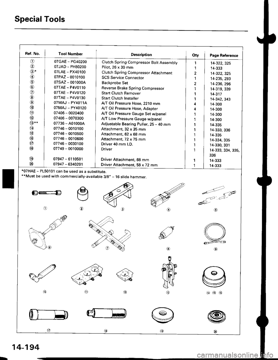
Ref. No. I Tool Number
o
@alr *
@
o
@6l
@
o
@
@-"
@
@
@
o
@
07GAE - PG40200
07JAD - PH80200
07LAE - PX40100
07PM - 0010100
07sM- 0010004
07TAE - P4V01l0
07TAE - P4V0120
07TAE - P4V0130
07 tvlAJ - PY4011A
07MAJ - PY40l20
07406 - 0020400
07406 - 0070300
07736 - A0r 0004
07746 - 0010100
07746 - 0010500
07746 - 0010600
07746 - 0030100
07749 - 0010000
07947 - 6110501
01947 - 6340201
Clutch Spring Compressor Bolt AssemblyPilot. 26 x 30 mm
Clutch Spring Compressor Attachment
SCS Service Connector
Backprobe Set
Reverse Brake Spring Compressor
Stan Clutch Remover
Stan Clutch Installer
A/T Oil Pressure Hose,2210 mmAy'T Oil Pressure Hose, Adapter
Ay'T Oil Pressure cauge Set WpanelAy'T Low Pressure Gauge w/panel
Adjustable Bearing Puller, 25 - 40 mmAttachment, 32 x 35 mm
Attachment, 62 x 68 mm
Attachment, 72 x 75 mm
Driver 40 mm l.D.
Driver
Driver Aftachment, 68 mm
Driver Attachment, 58 x 72 mm
I
1
2
Ia,l
1
1
1,1
1
1'1
I
1
1
't4-322,325
14-333
14-322,325't4-235,293
14-236, 296
r4-319,339't 4-311
14-342,343't4-300
14-300
14-300
14-300
14-335
14-333, 336
14-335
14-334, 335
14-330, 331
14-333, 334, 335,
336
14-333
14-333*07HAE - PL5010l can be used as a substitute.**Must be used with commercially-available 3/8.,- 16 slide hammer.
E*E
o
e
@
>.'.- -t-'- t'\;4
e'o
1:,'Jt*
dAt:-
io(313
@
@
@
@18l
aio
@
IR
L
14-194
Page 999 of 2189
Forward Clutch
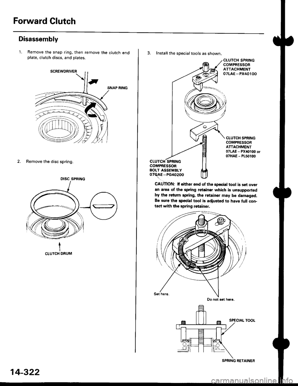
Disassembly
1. Remove the snap ring, then remove the clutch endplate, clutch discs, and plates.
SNAP RING
2. Remove the disc spring.
tCLUTCH DRUM
OISC SPRING
14-322
SPRING RETAINES
3. Install the specialtools as shown.
CLUTCH SPRINGCOMPRESSORBOLT ASSEMBLYo7R{E-PG402OO
CLUTCH SPRINGCOMPRESSORATTACHMENT07LAE - PX40100
CLUTCH SPRINGCOMPRESSORATTACHMENT07LAE - PXa0100 or07HAE - P150100
CAUTION: lf €ither ond of the sp€cial tool is sst overan aroa of the spring retainer which is unsupportedby th€ retum spring, the rotainer may be damaged.
Be sure the spccial tool is adiusted to hava tull con-taqt with the sp.ing retainer.
SPECIAL TOOL
Do not B€t here.
Page 1000 of 2189
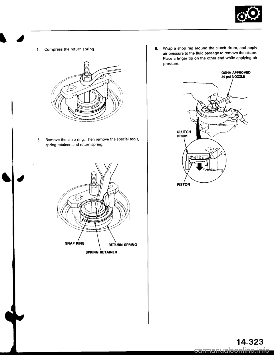
4. Compress the return sprlng.
Remove the snap ring. Then remove the special tools,
spring retainer, and return spring.
SPBING RETAIT{€R
6. Wrap a shop rag around the clutch drum, and apply
air pressure to the fluid passage to remove the piston.
Place a finger tip on the other end while applying air
pressure.
OSHA-APPROVED30 psi NOzzLE
14-323
Page 1002 of 2189
l.
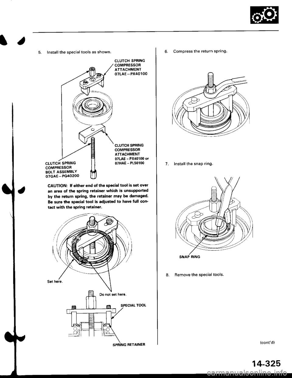
5. lnstallthe sDecialtools as shown.
CLUTCI{ SPRINGCOMPRESSORBOLT ASSEMBLYoTGAE-PG40200
CAUTION: lf either end of the special tool is set ovel
an area of lhe spring retain€r which is unsupported
by the return spring, tho retainsr may be damaged'
Be sure the special lool is adiusted to have full con-
tact with the spring tetainer.
Sgt h6r6.
SPECIAL TOOL
CLUTCH SPRINGCOMPRESSORATTACHMENT07LAE - PX40100
CLUTCH SPNINGCOMPRESSORATTACI{MENT07LAE - Pxil010o o.
07HAE - P150100
Do not sat hore.
6. Compress the return sPrlng'
7. Install the snap ring.
8. Remove the special tools.
(cont'd)
SIIAP RING
RETAINER
14-325
Page 1010 of 2189
Flywheel Housing
Input Shaft Oil Seal
l.
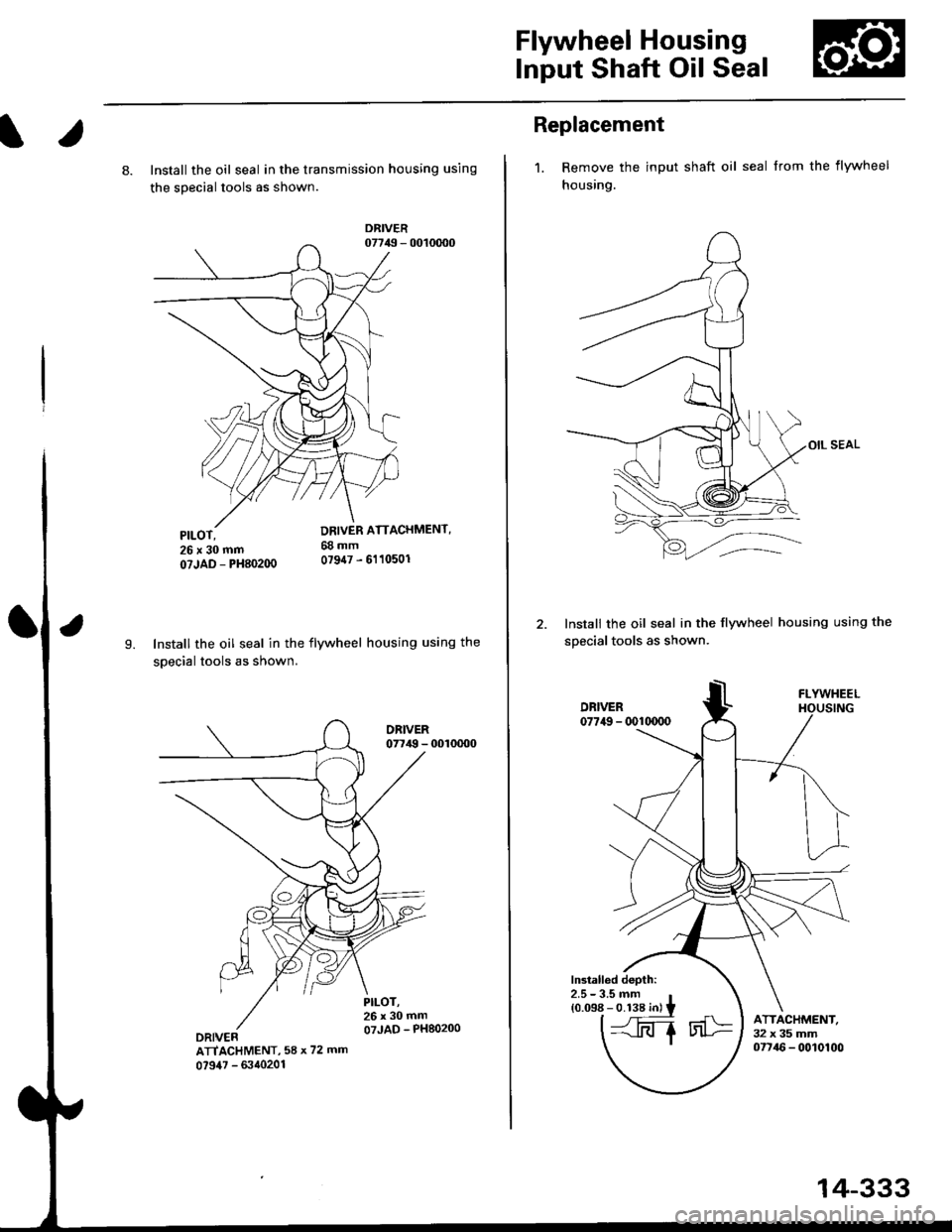
8. Install the oil seal in the transmission housing using
the sDecial tools as shown.
DRIVER07749 - 0010d)0
9.Install the oil seal in the flywheel housing using the
soecial tools as shown.
PILOT,26x30mmoTJAD - PH80200DRIVERATIACHMENT, 58 x 72 rnin
0?947 - d'40201
Replacement
1. Remove the input shaft oil seal from the flywheel
housing.
OIL SEAL
Instali the oil seal in the flywheel housing using the
soecialtools as shown.
FLYWHEEL
lmtalled depth:2.5- 3.5 mmro"nri':,ilii.rl
t@
14-333
Page 1011 of 2189
Transmission Housing Bearings
Driven Pulley Shaft Bearing Replacement
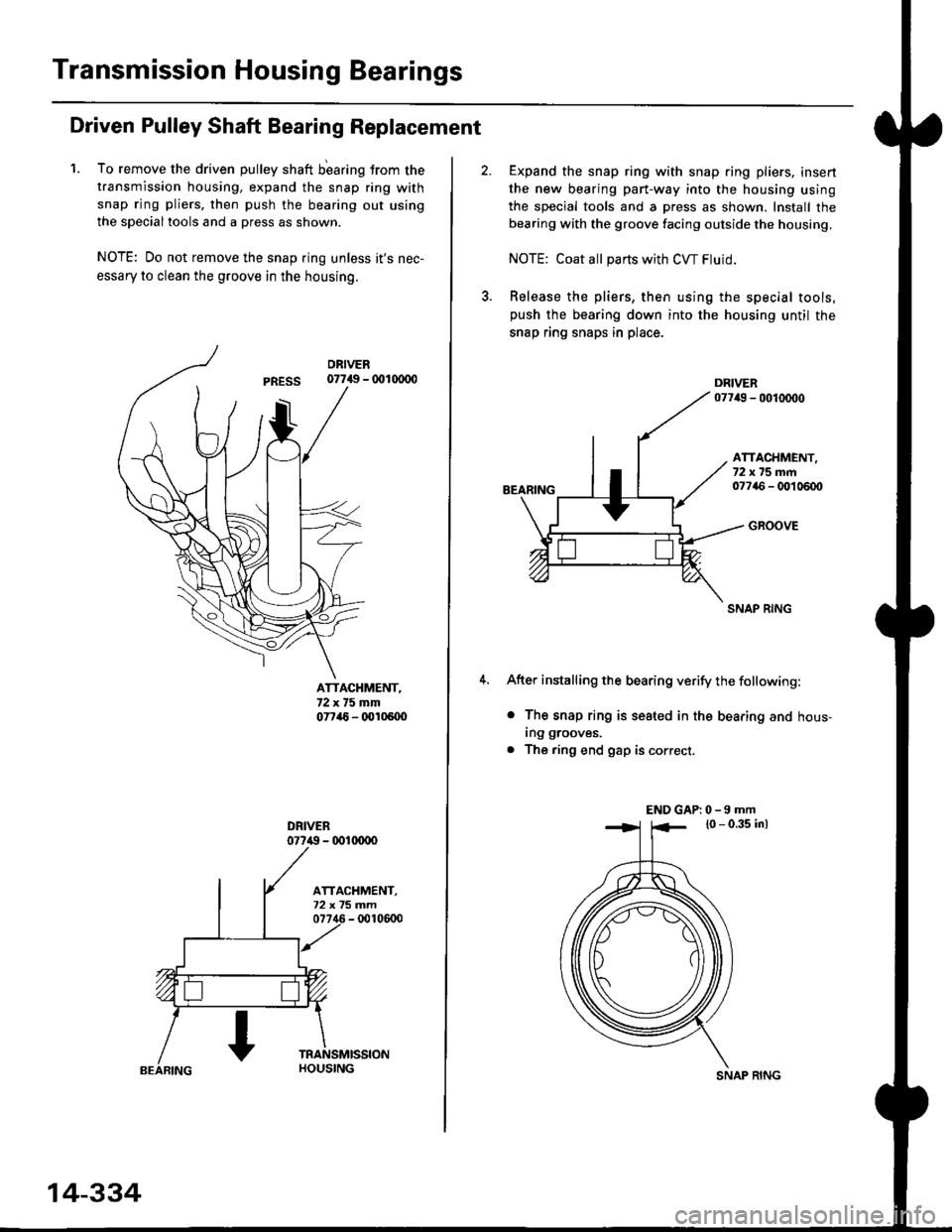
1. To remove the driven pulley shaft b'earing trom the
transmission housing, expand the snap ring with
snap ring pliers, then push the bearing out using
the specialtools and a press as shown.
NOTE: Do not remove the snap ring unless it's nec-
essary to clean the groove in the housing.
07749 - 001(xDo
ATTACHMENT,72x75mm07746 - (x'l05U)
077i() - 001(xrco
14-334
SNAP RING
Expand the snap ring with snap ring pliers, insert
the new bearing part-way into the housing using
the special tools and a press as shown. Install the
bearing with the groove facing outside the housing.
NOTE: Coat all pans with CW Fluid.
Release the pliers, then using the special tools,push the bearing down into the housing until the
snap ring snaps in place.
BEARING
ATTACHMENT,72x75mm07746 - OO1 0600
GROOVE
SNAP RING
After installing the bearing verify the following:
o The snap ring is seated in the bearing and hous-
ing grooves.
. The ring end gap is correct.
END GAP| 0 -9 mm
l0 - 0.35 inl
Page 1012 of 2189
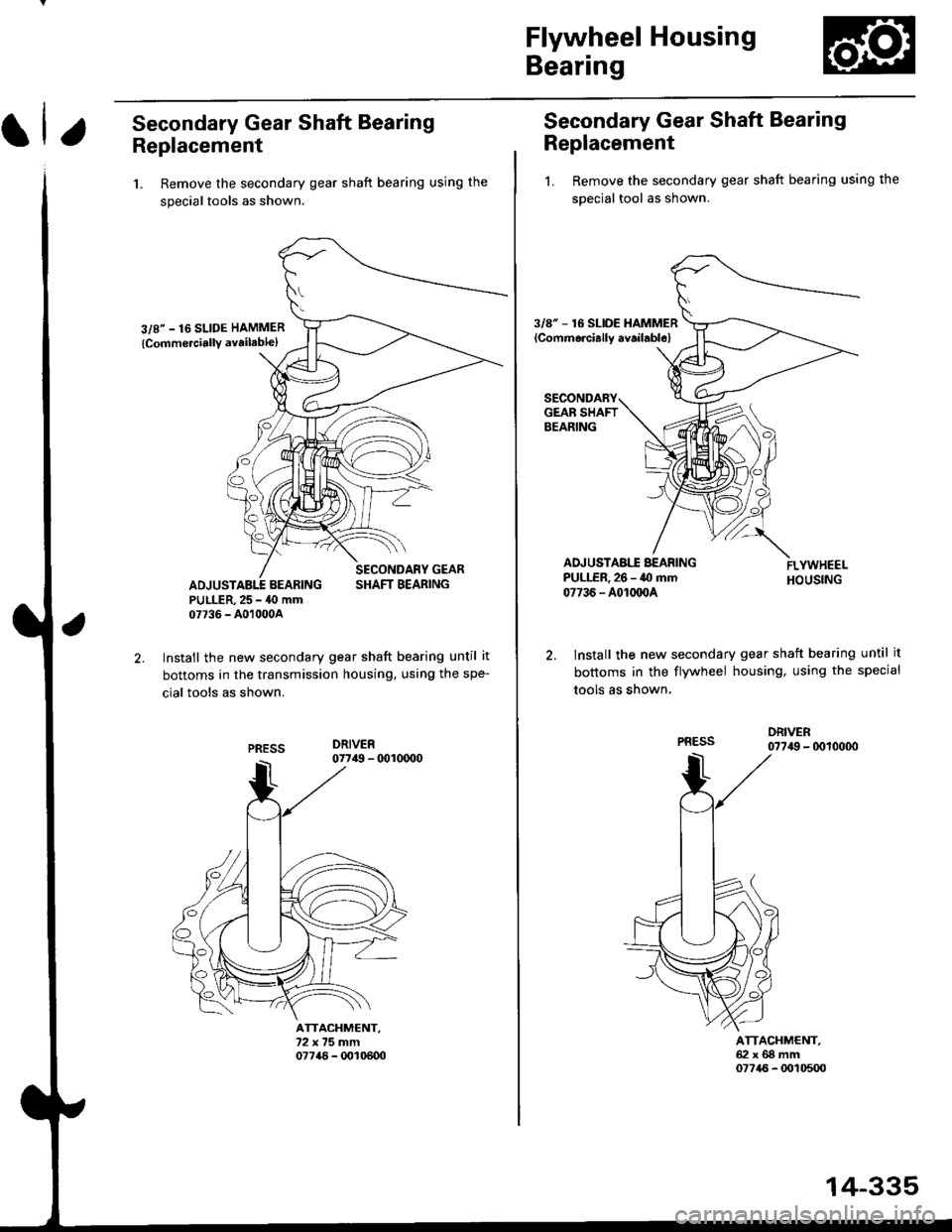
Flywheel Housing
Bearing
Secondary Gear Shaft Bearing
Replacement
1. Remove the secondary gear shaft bearing using the
special tools as shown.
3/8" - 16 SLIDE HAMMER
{Comm6rciallY availablel
SECONDARY GEAR
ADJUSTABI.T BEARING SHAFT BEARINGPULLER.25 - 40 mm07736 - A01000A
Install the new secondary gear shaft bearing until it
bottoms in the transmission housing. using the spe-
cial tools as shown.
Secondary Gear Shaft Bearing
Replacement
1. Remove the secondary gear shaft bearing using the
soecial tool as shown.
3/8" - 16 SLIDE HAMMER
lCommorcially aY.ilabl6l
2. lnstall the new secondary gear shaft bearing until it
bottoms in the flywheel housing, using the special
tools as shown.
DRIVER07749 - (x)10000
ATTACHMENT.62xGgmm07745 - 0010500
14-335
Page 1013 of 2189
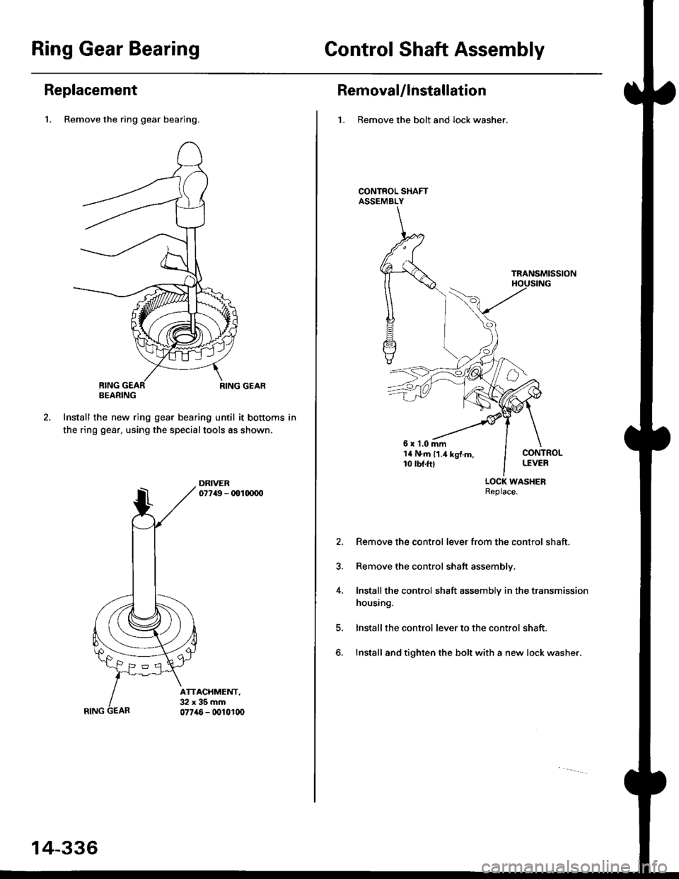
Ring Gear BearingControl Shaft Assembly
Replacement
1. Remove the ring gear bearing.
RING GEAR
Install the new ring gear bearing until it bottoms in
the ring gear. using the specialtools as shown,
DRIVER07?{9 - 001(xxxt
RING
14-336
RemovaUlnstallation
1. Remove the bolt and lock washer.
CONTROL SHAFTASSEMBLY
6r1.0mm14 N.ft 11.4 kg{.m,10 rbf.ftl
TRANSMISSION
CONTROLLEVER
LOCK WASHERReplace.
2. Remove the control lever from the control shaft.
3. Remove the control shaft assembly.
4. Install the control shaft assembly in the transmission
housing.
Install the control lever to the control shaft.
Install and tighten the bolt with a new lock washer.