AC control HONDA CIVIC 1996 6.G Owner's Manual
[x] Cancel search | Manufacturer: HONDA, Model Year: 1996, Model line: CIVIC, Model: HONDA CIVIC 1996 6.GPages: 2189, PDF Size: 69.39 MB
Page 140 of 2189
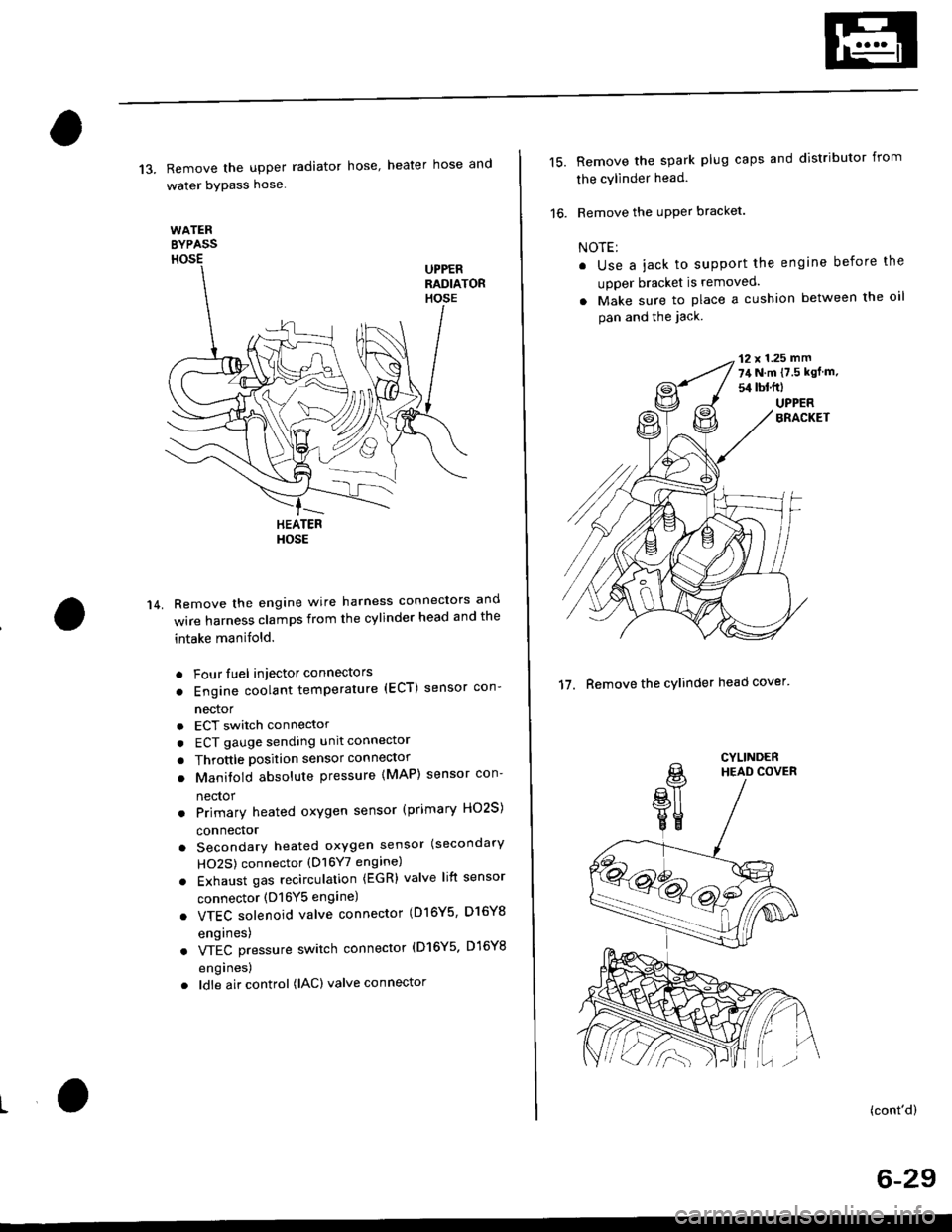
13. Remove the upper radiator hose' heater hose and
water bYPass hose
WATEREYPASSHOSEUPPERRADIATORHOSE
14.
HEATERHOSE
Remove the engine wire harness connectors and
wire harness clamps from the cylinder head and the
intake manifold.
o Four fuel injector connectors
. Engine coolant temperature (ECT) sensor con-
nector
a
a
a
ECT switch connector
ECT gauge sending unit connector
Throttle position sensor connector
Manitold absolute pressure (MAP) sensor con-
nector
Primary heated oxygen sensor (primary HO2S)
connector
Secondary heated oxygen sensor (secondary
HO2S) connector (D16Y7 engine)
Exhaust gas recirculation (EGR) valve lift sensor
connector (D16Y5 engine)
. VTEC solenoid valve connector (Dl6Y5, D16Y8
engrnes)
. VTEC pressure switch connector (D16Y5. D16Y8
engrnes,
. ldle air control (lAC) valve connector
15.Remove the spark plug caps and distributor from
the cylinder head.
Remove the uPPer bracket.
NOTE:
. Use a jack to support the engine before the
upper bracket is removed.
. Make sure to place a cushion between the oil
pan and the jack.
12 x 1.25 mm
74 N.m {7.5 kgf m.
sil lbl.ftl
UPPERBRACKET
'17. Remove the cylinder head cover'
CYLINDERHEAD COVER
(cont'd)
6-29
Page 155 of 2189
Valves
Camshaft/Rocker Arms and
Camshaft Seal/Pulley
Installation (cont'd)
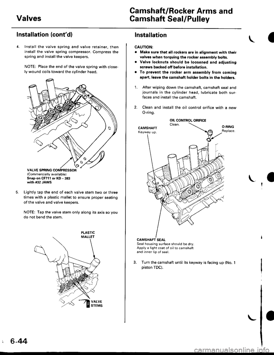
4. Install the valve spring and valve retainer. then
install the valve spring compressor. Compress the
spring and installthe valve keepers.
NOTE: Place the end of the valve spring with close-
ly wound coils toward the cylinder head.
lCornmercially available)Snap-on CFrll or KD - 3tX'with #32 JAWS
Lightly tap the end of each valve stem two or three
times with a plastic mallet to ensure proper seating
of the valve and valve keepers.
NOTE: Tap the valve stem only along its axis so you
do not bend the stem.
' 6-44
Installation
CAUTION:
. Make sure that all tockers are in alignment with their
valvgs when torquing the rocket assembly bolts,. Valve locknuls should be loosened and adiusting
screws backed off bofore installation.
. To prevont tho rocker arm a$smbly from coming
apad, l6av€ the camshaft holder bohs in the holdeB.
1. After wiping down the camshaft, camshaft seal andjournals in the cylinder head, lubricate both sur-
faces and install the camshaft.
2. Clean and install the oil control orifice with a new
O-ring.
CAMSHAFT SEALSeal housing surface should be dry.Apply a light coat of oil to camshaftand inner lip of seal.
3. Turn the camshaft until its keyway is facing up (No.
piston TDC).
OIL CONTROL ORIFICE
Page 156 of 2189
Cylinder Head
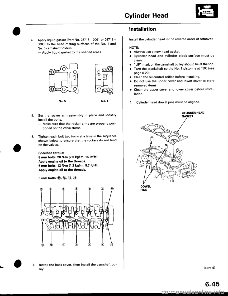
4. Apply liquid gasket (Part No. 08718 - 0001 or 08718 -
0003) to the head mating surfaces of the No. 1 and
No.5 camshaft holders.- Apply liquid gasket to the shaded areas
Set the rocker arm assemblY in place and loosely
installthe bolts.- Make sure that the rocker arms are properly posi-
tioned on the valve stems.
Tighten each bolt two turns at a time in the sequence
shown below to ensure that the rockers do not bind
on the valves.
Specitied torquo:
8 mm bolts: 20 N.m (2.0 kgt'm, l/t lbf'ft)
Apply engine oil to the threads.
6 mm bolts: 12 N.m {1.2 kgif'm, 8.7 lbf'ft)
Apply engine oil to the thresds.
6 mm bolts: O, @. @, @
7. Install the back cover. then install the camshaft pul-!
6-45
lnstallation
lnstallthe cylinder head in the reverse order of removal:
NOTE:
. Always use a new head gasket.
. Cylinder head and cylinder block surface must be
clean.
. "UP" mark on the camshaft pulley should be at the top
. Turn the crankshaft so the No. 1 piston is at TDC (see
page 6-20).
. Clean the oil control orifice before installing.
a Do not use the upper cover and lower cover to store
removeo rlems.
Clean the upper cover and lower cover before instal-
taUon.
Cylinder head dowel pins must be aligned.1.
CYUNOER HEAD
PINS
(cont'd)
Page 161 of 2189
VTEC Control SYstem
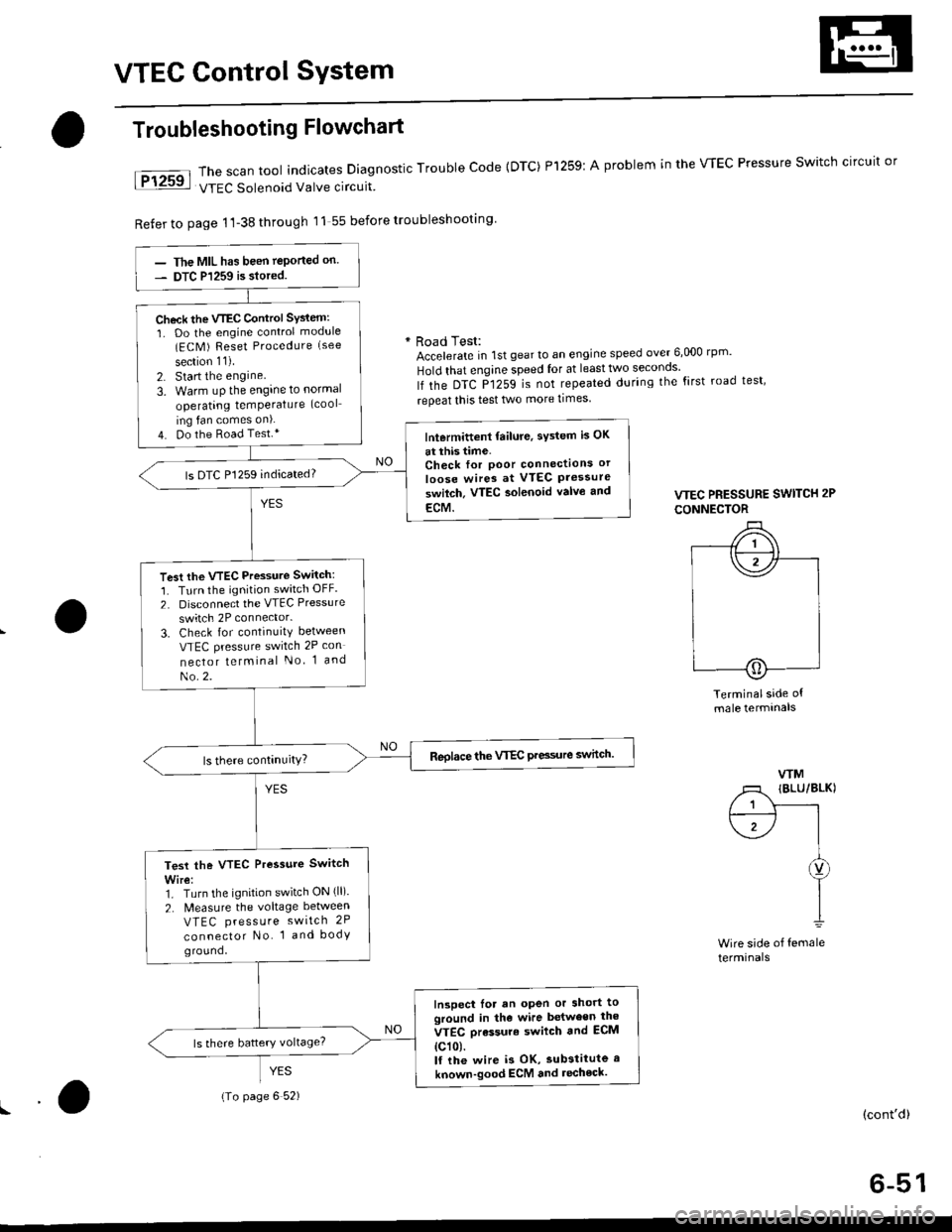
The scan tool indicates Diagnostic Trouble Code {DTC) Pl259:
VTEC Solenoid Valve circuit
Refer to page 1'l-38 through 11 55 before troubleshooting
Troubleshooting Flowchart
YES
A problem in the WEC Pressure Switch circuit or
* Road Test:Accelerate in 1st gear to an engine speed over 6,000 rp '
Hold that engine speed for at leasttwo seconos'
lf the DTC P1259 is not repeated during the first road test'
repeat this test two more times
VTEC PRESSURE SWITCH 2P
CONNECTOR
Terminalside ofmale termtnals
WM
/1 IBLU/BLKI
/ 1 Y------rt--------- l I
\1-/ |I
I
I1
Wire side of femaleterminals
(cont'd)
6-51
The MIL has been teported on.
DTC P1259 is siored.
Check the VTEC Control SYsiem:
1. Do the engine control module(ECM ) Reset Procedure (see
section 11).
2. Start the engine
3. Warm uP the engine to normal
operating temPerature (cool
ing fan comes on).
4. Do the Road Test.*lntermittent failure, sYstem is OK
at this time.Check for Poor connectlons or
loose wires at VTEC Pressureswilch. VTEC aolenoid valvo and
ECM.
ls DTC P1259 indicated?
Test the VTEC Pressure Switch:
1. Turn the ignition switch OFF.
2. Disconnect the VTEC Pressure
switch 2P connector.
3. Check for continuity between
VTEC pressure switch 2P con
nector telminal No 1 and
No.2.
Reolace the VTEC Pre3sure switch.
Test the VTEC Pressure Switch
Wire:1. Turn the ignition switch ON (ll).
2. N4easure the voltage between
VTEC press u re switch 2P
connector No. 1 and bodyground,
Inspect lor an open or short toground in the wire between the
VTEC orassure swilch and ECM
{c101.lf the wire i3 OK, substitute a
known-good ECM and recheck.
{To page 6 52)
Page 162 of 2189
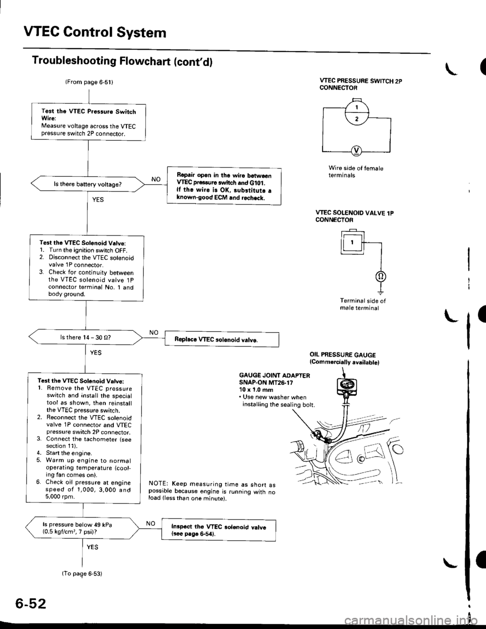
VTEC Control System
Troubleshooting Flowchart (cont,d)
VTEC PRESSURE SWITCH 2PCONNECTOR
Wire side of temaleterminals
OIL PRESSURE GAUGE(Comm.rcially avail.bte)
GAUGE JOINT ADAPTERSNAP.ON MT26.1710 x 1.0 ftm. Use new washer wheninstalling the sealing bott.
NOTE: Keep measuring time as shorr aspossible because engine is running witn noload lless than one minute).
6-52
(
VTEC SOLENOID VALVE lPCONNECTOF
Ir------r I
lLl.ll-r
II
It
Terminal side ofmale terminal
I
(From page 6-5l l
(To page 6-53)
Test tha VTEC P.es3uro SwitchWi.e:Measure voltage across the VTECpressure switch 2P connector.
Ropair opon in the wiro batwoenVIEC pr...urc switch and G lot .lf the wiro is OK, 3ubltitutr aknown-good ECM and rochack.
ls there battery voltage?
Test the VTEC Solenoid V.tve:1. Turn the ignition switch OFF.2. Disconnect the VTEC solenoidvalve 1P connector.3. Check for continuity betweenthe VTEC solenoid valve 1Pconnector terminal No, I andbody ground.
ls there 14 - 30 O?
Te3t the VTEC Sotonoid Vatve:'1. Remove the VTEC pressureswitch and install the specialtool as shown. then reinstallthe VTEC pressure switch.2. Reconnect the VTEC solenoidvalve 1P connector and VTECpressure switch 2P connector,3. Connect the tachometer (seesection 1l).4. Start the engine.5. Warm up engine to normaloperatrng temperature (cool-ing fan comes on).6. Check oil pressure at enginespeed of 1,000,3,000 and5,000 rpm.
ls pressure below 49 kPa(0.5 kgflcm,,7 psi)?Inipoct thg VTEC aolenoid valvel3ee P8go 6-54).
I
Page 176 of 2189
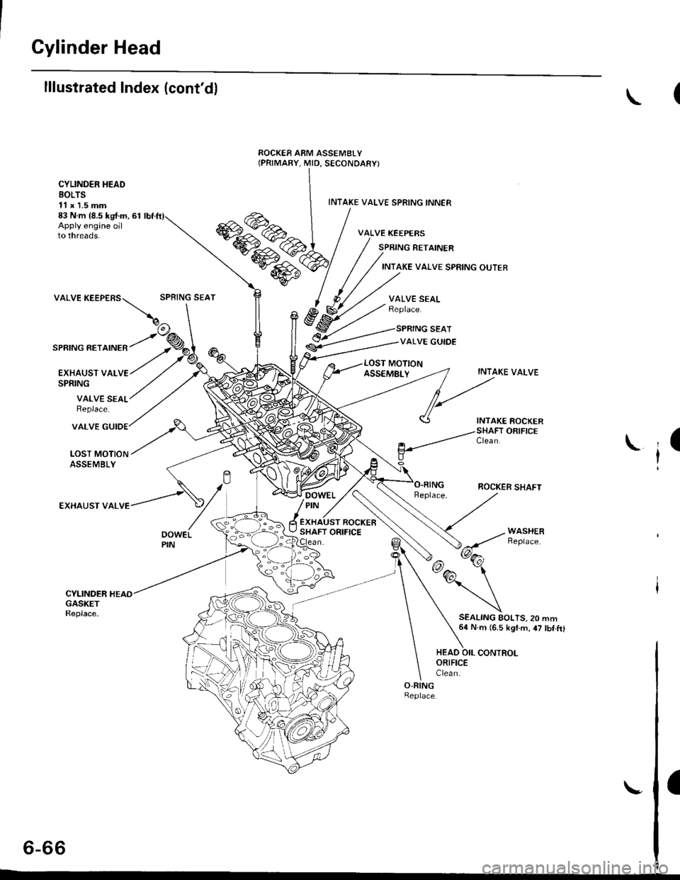
Cylinder Head
lllustrated Index (cont'dl
CYLINDER HEADBOLTS11 x 1.5 mm83 N.m {8.5 kg{.m, 61Apply engine oilto threads.
INTAKE VALVE SPRING INNER
VALVE KEEPERS
SPRING RETAINER
INTAKE VAI.VE SPRING OUTER
valvEKEEPEBS\:""j"*'
SPRING RETAINER
EXHAUST VALVESPRING
VALVE SEALReplace.
VALVE
LOST MOTIONASSEMBLY
EXHAUST VAL
VALVE SEALReplace.
SPRING SEAT
VALVE GUIDE
INTAKE VALVE
ROCKER SHAFT
SEALING AOLTS.20 mm64 N.m (6.5 kgt.m, 47 tbf.ft)
t
il
HEAO OIL CONTROLORIFICEClea n.
a
6-66
Page 178 of 2189
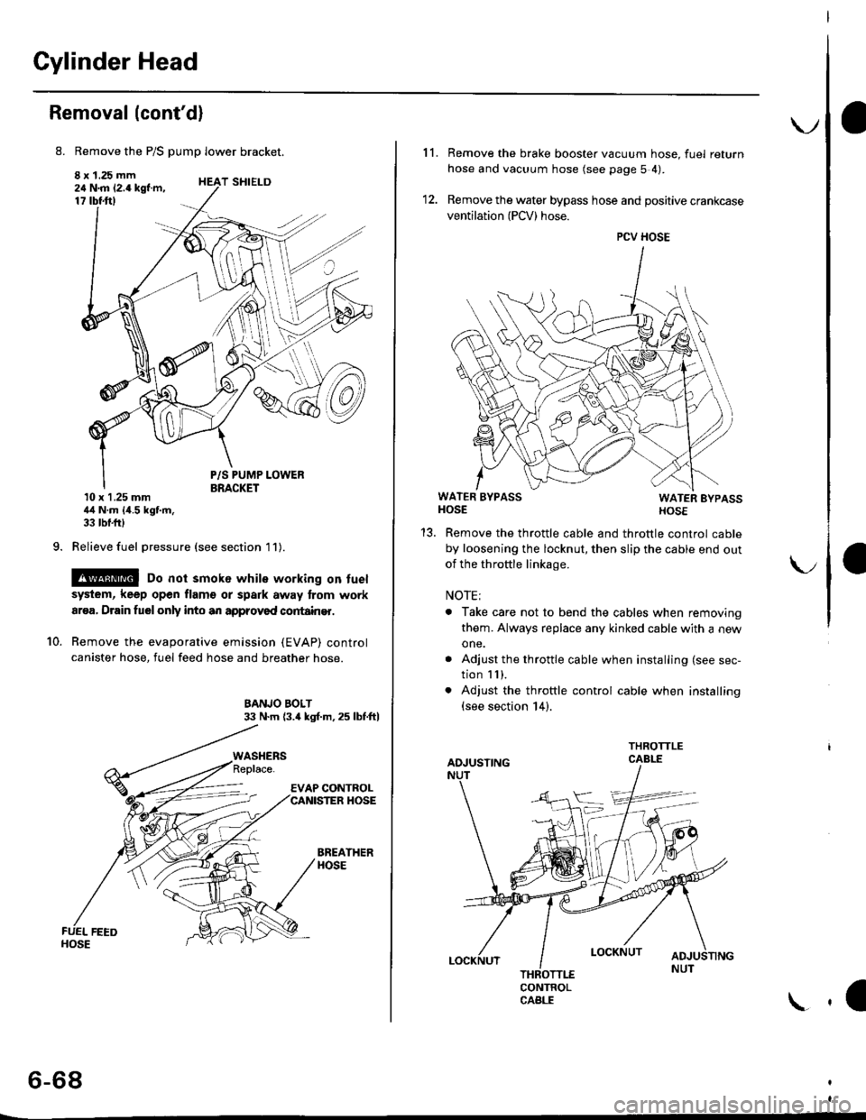
Cylinder Head
Removal (cont'd)
8. Remove the P/S pump lower bracket.
8 x 1.25 mm24 N.m 12.4 kgf.m,17 tbtftl
9.
T SHIELD
10.
P/S PUMP LOWERBRACKET10 x 1.25 mm44 N.m {4.5 kgf.m,33 tbf.frl
Relieve fuel pressure (see section l1).
@ Do not smok6 while working on fuel
system, keep open flam€ or spark away lrom work
ar€a, Drain fuelonly into an approved cortain€r.
Remove the evaporative emission (EVAP) control
canister hose, fuel feed hose and breather hose.
BANJO BOLT33 N.m (3.4 kgl.m.25 lbf.ftl
BREATHERHOSE
WASHERS
6-68
\.
11. Remove the brake booster vacuum hose, fuel return
hose and vacuum hose (see page 5 4).
12. Remove the water bypass hose and positive crankcase
ventilation (PCV) hose.
WATER BYPASSHOSEWATER EYPASSHOSE
Remove the throttle cable and throttle control cable
by loosening the locknut, then slip the cable end out
of the throftle linkage.
NOTE;
. Take care not to bend the cables when removing
them. Always replace any kinked cable with a new
one.
. Adjust the throttle cable when installing (see sec-
tion I I ),. Adjust the throttle control cable when installing(see section 14).
CONTROLCABLE
1a
PCV HOSE
Page 179 of 2189
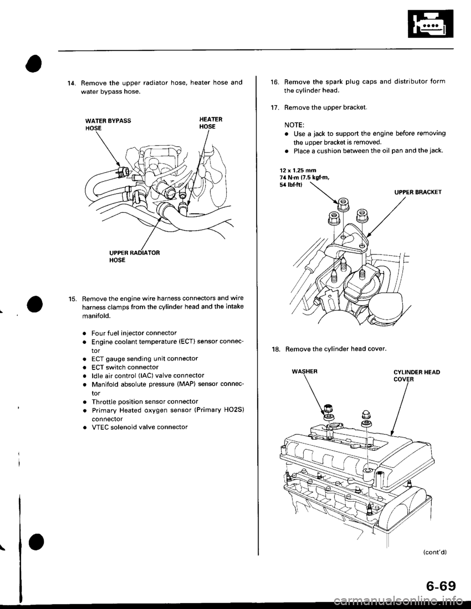
WATER BYPASS
HOSE
14. Remove the upper radiator hose, heater hose and
water bvpass hose.
HEATER
Remove the engine wire harness connectors and wlre
harness clamps from the cylinder head and the intake
manifold.
Four fuel injector connector
Engine coolant temperature (ECT) sensor connec-
tor
ECT gauge sending unit connector
ECT switch connector
ldle air control (lAC) valve connector
Manifold absolute pressure (MAP) sensor connec-
tor
Throttle position sensor connector
Primary Heated oxygen sensor (Primary HO2S)
connecror
VTEC solenoid valve connector
15.
a
a
a
a
a
\
16.
17.
Remove the spark plug caps and distributor form
the cylinder head.
Remove the upper bracket.
NOTE:
. Use a jack to support the engine before removing
the upp€r bracket is removed.
. Place a cushion between the oil panandthejack.
12 x 1.25 fin74 N.m 17.5 kgtm,
UPPER BRACKET
18. Remove the cylinder head cover.
{cont'd)
6-69
Page 194 of 2189

I
Cylinder Head
Installation
lnstall the cylinder head in the reverse order of removal:
NOTE:
. Always use a new head and manifold gasket.. The cylinder head gasket is a metal gasket, Take carenot to bend it.
. Rotate the crankshaft, set the No. 1 piston at TDC (seepage 6-63).
. Do not use the middle cover and lower cover forstorang removed items.. Clean the middle cover and lower cover before instal_lation.
o Replace any washers that are damaged or deteriorated.
1. Install the cylinder head gasket, dowel pins and thehead oil control orifice on the cylinder head.
NOTE: Clean the oil control orifice when installing.
DOWEL PIN
6-84
2, Tighten the cylinder head bolts in two steps. In thefirst step, tighten all bolts in sequence to about 29N.m (3.0 kgf.m, 22 tbf.ftl. ln the final step, tighten inthe same sequence to 83 N.m (8.S kgf.m,6t lbf.ft).
NOTE:
. Apply clean engine oil to the bolt threads andunder the bolt head.. We recommend using a beam-type torquewrench. When using a preset-type torque wrench,be sure to tighten slowly and not to overtighten.. lf a bolt makes any noise while you are torquing it,loosen the bolt, and retighten it from the 1st step.
CYLINDER HEAD BOLT TOROUE SEOUENCE
11x 1.5 mm83 N.m 18.5 kgf.m, 61 tbf.ftl
Install the intake manifold and tighten the nuts in acflsscross pattern in two or three steps, beginningwith the inner nuts.. Always use a new intake manifold gasket.
Install the exhaust manifold and tighten the newself-locking nuts in a crisscross pattern in two orthree steps. beginning with the inner nuts.. Always use a new exhaust manifold gasket.
4.
Page 244 of 2189
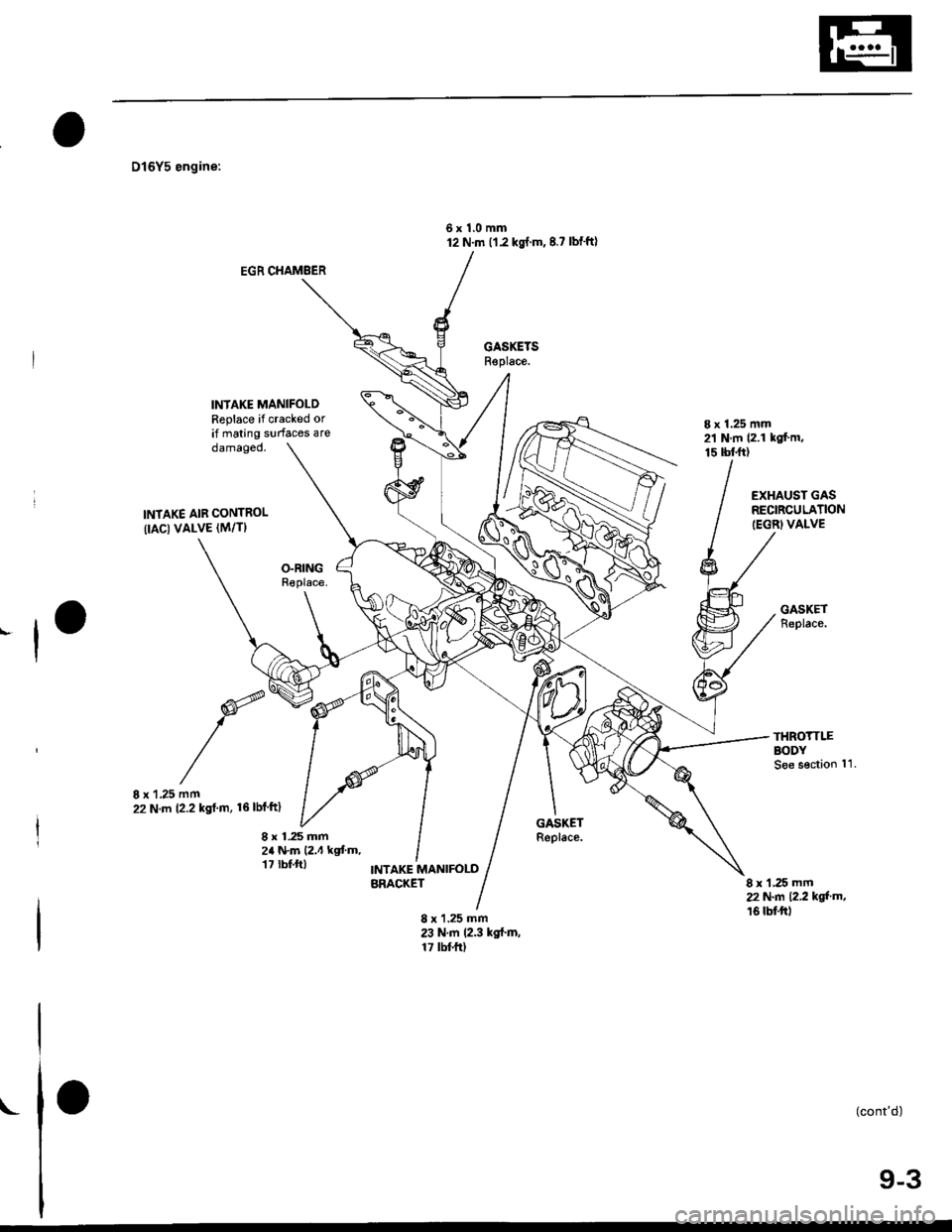
D16Y5 engine:
6x1.0mm12 N'm (1.2 kgl.m,8.? lbf'ft)
EGR CHAMBER
INIAKE MANIFOLDReplace if cracked orif mating surfaces are8 x 1.25 mm21 N m (2.1 kgf.m,15 tbtft)damageo,
INTAKE AIB CONTROL(IAC) VALVE (M/TI
8 x'1,25 mm22 N.m (2.2 kst m, 16lblftl
8 r 1.25 mm2a N.m (2.4 kgt m,17 rbt.ft)
EXHAUST GASRECIRCULATION(EGRIVALVE
8 x 1,25 mm22 N.n 12.2 kol'm,16 tbftr)
INTAKE MANIFOLDBRACKET
8 x 1.25 mm23 N.m 12.3 kgf'm,17 tbt fr)
(cont'd)I
9-3